EP0434078B1 - Séparateur de liquides légers - Google Patents
Séparateur de liquides légers Download PDFInfo
- Publication number
- EP0434078B1 EP0434078B1 EP90125066A EP90125066A EP0434078B1 EP 0434078 B1 EP0434078 B1 EP 0434078B1 EP 90125066 A EP90125066 A EP 90125066A EP 90125066 A EP90125066 A EP 90125066A EP 0434078 B1 EP0434078 B1 EP 0434078B1
- Authority
- EP
- European Patent Office
- Prior art keywords
- guide tube
- suction hose
- light liquid
- follows
- separator according
- Prior art date
- Legal status (The legal status is an assumption and is not a legal conclusion. Google has not performed a legal analysis and makes no representation as to the accuracy of the status listed.)
- Expired - Lifetime
Links
- 239000007788 liquid Substances 0.000 title claims abstract description 51
- 238000003860 storage Methods 0.000 claims description 15
- 239000002351 wastewater Substances 0.000 claims description 5
- 238000010276 construction Methods 0.000 claims description 2
- 239000000725 suspension Substances 0.000 claims description 2
- 238000007789 sealing Methods 0.000 claims 2
- XLYOFNOQVPJJNP-UHFFFAOYSA-N water Substances O XLYOFNOQVPJJNP-UHFFFAOYSA-N 0.000 description 20
- 239000000203 mixture Substances 0.000 description 6
- 238000000926 separation method Methods 0.000 description 6
- 239000003921 oil Substances 0.000 description 4
- 230000001914 calming effect Effects 0.000 description 3
- 238000012423 maintenance Methods 0.000 description 3
- 230000000694 effects Effects 0.000 description 2
- 238000000605 extraction Methods 0.000 description 2
- 239000000446 fuel Substances 0.000 description 2
- 238000005086 pumping Methods 0.000 description 2
- 238000004140 cleaning Methods 0.000 description 1
- 238000005260 corrosion Methods 0.000 description 1
- 230000007797 corrosion Effects 0.000 description 1
- 239000003651 drinking water Substances 0.000 description 1
- 235000020188 drinking water Nutrition 0.000 description 1
- 239000012530 fluid Substances 0.000 description 1
- 230000005484 gravity Effects 0.000 description 1
- 239000002920 hazardous waste Substances 0.000 description 1
- 238000010438 heat treatment Methods 0.000 description 1
- 238000007654 immersion Methods 0.000 description 1
- 238000011065 in-situ storage Methods 0.000 description 1
- 238000003780 insertion Methods 0.000 description 1
- 230000037431 insertion Effects 0.000 description 1
- 238000012432 intermediate storage Methods 0.000 description 1
- 239000000314 lubricant Substances 0.000 description 1
- 238000004519 manufacturing process Methods 0.000 description 1
- 239000000463 material Substances 0.000 description 1
- 239000002480 mineral oil Substances 0.000 description 1
- 235000010446 mineral oil Nutrition 0.000 description 1
- 230000002093 peripheral effect Effects 0.000 description 1
- 239000010865 sewage Substances 0.000 description 1
- 239000000126 substance Substances 0.000 description 1
- 239000002699 waste material Substances 0.000 description 1
Images
Classifications
-
- E—FIXED CONSTRUCTIONS
- E03—WATER SUPPLY; SEWERAGE
- E03F—SEWERS; CESSPOOLS
- E03F5/00—Sewerage structures
- E03F5/14—Devices for separating liquid or solid substances from sewage, e.g. sand or sludge traps, rakes or grates
- E03F5/16—Devices for separating oil, water or grease from sewage in drains leading to the main sewer
-
- B—PERFORMING OPERATIONS; TRANSPORTING
- B01—PHYSICAL OR CHEMICAL PROCESSES OR APPARATUS IN GENERAL
- B01D—SEPARATION
- B01D17/00—Separation of liquids, not provided for elsewhere, e.g. by thermal diffusion
- B01D17/02—Separation of non-miscible liquids
- B01D17/0208—Separation of non-miscible liquids by sedimentation
- B01D17/0214—Separation of non-miscible liquids by sedimentation with removal of one of the phases
Definitions
- the invention relates to a light liquid separator according to the preamble of claim 1.
- Rainwater and dirty water which is caused by light liquids, e.g. Gasoline or heating oil, contaminated with a density of up to 0.95 g / cm3, e.g. in the maintenance, refueling and cleaning of vehicles, in systems for storing, filling and handling fuels, oils or lubricants, such as when storing and handling materials containing mineral oil, pretreatment in a light liquid separator is required before they can be discharged.
- Light liquid separators consist of a receptacle, in which the dirty water loaded with light liquid is temporarily stored and calmed down. The intermediate storage and calming effect that the amount of light liquid automatically collects above the water level due to its lower inherent density. DIN 1999 specifies that such light liquid separators are to be emptied at least four times a year with a separated light liquid quantity corresponding to 4/5 of the storage quantity.
- separators with suction devices are known which allow the light liquid separated above the water level to be extracted only up to a certain level of the storage content of the separator. This ensures that only separated light liquid, but not the water underneath, is sucked off.
- the device known from GB-A-1 600 791 works to ensure the extraction only up to a certain level in the manner of a skimmer or an overflow protection, in which a drain pipe with its drain or overflow opening points upward within the liquid is. For the removal of the light liquid located above its rim only a locking device cooperating with this tube is opened.
- the other such device known from DE-A-3 612 288 for ensuring the extraction of the light liquid only up to a certain level works with a sensor which responds to a predetermined level of the water or oil level and drives one with Switches on the connected pump if the water or oil level has reached the level.
- This complicated control device is also exposed to interference from the harsh environment of the location of such a separator.
- a further device for separating gasoline or other corresponding fuels from the wastewater is known, which can preferably be used wherever easily flammable substances are handled, which have to be collected and to prevent that they enter the sewage system with the waste water.
- several chambers, some of which are provided with baffles, are arranged in the device, in which the waste water flow is slowed down and the light liquid carried therein is separated.
- the light liquid from separators of the aforementioned type is usually emptied through an access shaft from above by suction using an inserted suction nozzle or suction hose. Usually it is the suction hose of a disposal vehicle.
- EP-A-0 046 277 shows and describes a device for gravity separation of liquid mixtures, which has a separation space for separating the components of the liquid mixture, an inlet device with one or more inlet openings for the liquid mixture and an outlet for one of the components of the liquid mixture .
- the liquid flowing in from the inlet device maintains a direction of flow which deviates by at least 90 ° from the direct connection line between inlet and outlet.
- the heavier component of the liquid mixture settles in the separation chamber, while the lighter liquid can flow off with the interposition of a float-controlled valve.
- the invention has for its object to provide a separator of the type mentioned, which avoids this unnecessary effort and ensures that the amount of light liquid emptied is only loaded with a minimal optimum of water in the sense of the desired savings.
- a guide tube projecting downward from the shaft opening is provided for the enclosure and the peripheral separation of the suction hose from the storage contents, that the lower end of the guide tube has a storage-liquid-permeable lowering limiting device for the suction hose inserted therein, and that the suctioning device is provided by the lowering limiting device the light liquid is guaranteed through the suction hose to the waste water level.
- the inside diameter of the guide tube used is expediently dimensioned such that all customary suction hoses, possibly also those with screwed flanges which are fastened at the ends and project radially beyond the circumference of the hose, can be inserted into the guide tube.
- the guide tube can, for example, be provided with a maximum inner diameter, which enables the trouble-free insertion and reception of any conventional suction hose.
- the jacket of the guide tube surrounds the suction hose and that the suction can take place up to the predetermined level at the lower end of the guide tube.
- the guide tube has an end stop for the suction hose at its lower end as a lowering limiting device which is permeable to storage liquid.
- a closure basket is advantageously provided as an end stop for the suction hose.
- the separator according to the invention has the effect that the professional disposal company does not have to take any particular care or caution when emptying only the separated light liquid from the separator in order to achieve this goal.
- the disposal company only has to insert the suction hose into the guide tube until the end of the suction hose strikes the lowering limiting device. The suction hose cannot be lowered further.
- the closure basket or its base is adjustable in height and thus to a specific one Preset level of the memory content is arranged on the stationary fixable guide tube.
- a preferred further development can consist in that a locking device covering the cross section of the manhole except for a passage for the suction hose is provided, which can be detachably attached to the receptacle. This ensures that the suction hose cannot be lowered past the guide tube and thus indefinitely into the receiving container of the separator.
- the locking device is expediently a grating which is at the same time the hanger for the guide tube which is guided upwards through the locking device and is detachably fastened to the receptacle, for example by a screw connection.
- the detachability is necessary because, for example, the interior of the separator must also remain accessible for control and repair purposes. However, it is to be prevented that the disposal company can simply lift the locking device and thus can simply cancel its intended use.
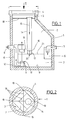
- the light liquid separator contains a receptacle 1, which can be prefabricated from concrete parts, for example. Production from in-situ concrete can also be carried out depending on the size and operating conditions.
- the receptacle 1 In the installed position, the receptacle 1 is usually sunk into the ground. Its interior 2 is then only accessible from above through a manhole 3.
- the opening 4 of the manhole 3 can be closed by a manhole cover-like cover (not shown).
- the receptacle 1 contains an inlet pipe 5 for the dirty water loaded with light liquid.
- the polluted dirty water flows from the inlet pipe 5 via a calming compartment 6 into the storage space 7 the separation process takes place automatically because the light liquid separates above the water due to its lower density than water.
- the outflow 8 for the water separated from the light liquid starts from the level of approximately the bottom 9 of the receptacle 1.
- the drain line still running within the storage space 7 has the reference number 10.
- the entry opening 11 into the drain line 10 located in the area of the bottom 9 can be closed by an automatically operating closure device 12.
- the closure device 12 is controlled by a float 13. If the amount of light liquid separating above the water content becomes too large, the float 13 sinks downward and the closure device 12 closes the inlet opening 11. This is also the signal for the user that the separator must be emptied.
- the guide tube 14 projecting downward from the shaft opening 4 is used for enclosing and circumferentially separating the suction hose, not shown, introduced from above in the direction of the arrow 15 from the storage contents.
- the guide tube 14 is provided at its lower end 16 with a sieve-like lowering device in the form of a closure basket 17 which is therefore permeable to storage fluid.
- the opening 4 is blocked by a locking device covering the cross section of the manhole 3 in the form of a grating 18, which forms a passage for the guide tube 14, in particular is designed as a suspension bracket for the guide tube 14.
- the grating 18 is detachably attached to the receptacle 1, more precisely to the manhole 3 in the area of the attachment points 19.
- At least one of the fastening points 19 is a screw connection, so that the grating 18 cannot be easily removed or lifted out of its fixing position shown in FIG. 1.
- the distance between the individual struts of the grating 18 is chosen so that the suction hose cannot be passed through the spaces.
- the suction hose can only be lowered in the direction of arrow 15 into the guide tube 14 in the direction of the storage content.
- the effect of the subject matter of the invention is that the disposal company only has to insert the suction hose into the guide tube 14 and lower it until the suction hose strikes the bottom 20 of the closure basket with its suction mouth.
- the optionally adjustable positioning of the bottom 20 of the closure basket 17 determines the level 21 or the layer height up to which a maximum suction of the storage contents is possible without this requiring special attention from the disposal company.
- the bottom 20 of the closure basket 17 can be set to a critical level 21, at which the closure device 12 blocks the drain 8. If the memory content of the receptacle 1 is then emptied, it is ensured that this emptying practically only affects the separated light liquid located above the level 21 and not the dirty water underneath it which is freed from the light liquid.
Landscapes
- Chemical Kinetics & Catalysis (AREA)
- Chemical & Material Sciences (AREA)
- Physics & Mathematics (AREA)
- Thermal Sciences (AREA)
- Engineering & Computer Science (AREA)
- Hydrology & Water Resources (AREA)
- Public Health (AREA)
- Water Supply & Treatment (AREA)
- Life Sciences & Earth Sciences (AREA)
- Health & Medical Sciences (AREA)
- External Artificial Organs (AREA)
- Infusion, Injection, And Reservoir Apparatuses (AREA)
- Sewage (AREA)
- Loading And Unloading Of Fuel Tanks Or Ships (AREA)
Claims (8)
- Séparateur de liquides legers avec bac de réception (1), le liquide leger séparé pouvant être évacué du haut à travers l'ouverture (4) d'un puits d'entrée (3) par aspiration au moyen d'un tuyau d'aspiration,
caractérisé en ce que
un tube de guidage (14) s'étendant vers le bas est prévu pour entourer et séparer la périphérie du tuyau d'aspiration, du contenu du réservoir, en ce que l'extrémité inférieure (16) du tube de guidage (14) est pourvue d'un dispositif de limitation de descente, perméable au liquide contenu dans le réservoir, pour le tuyau d'aspiration guidé dans ce tube, et en ce que le dispositif de limitation de descente garantit l'aspiration du liquide leger au moyen du tuyau d'aspiration jusqu'au niveau des eaux usées. - Séparateur selon la revendication 1,
caractérisé en ce que
le dispositif de limitation de descente, perméable au liquide contenu dans le réservoir, qui se trouve à l'extrémité inférieure (16) du tube de guidage (14) est une butée finale pour le tuyau d'aspiration. - Séparateur selon l'une des revendications 1 ou 2,
caractérisé en ce que
un panier de fermeture (17) est prévu à l'extrémité inférieure (16) du tube de guidage (14) en tant que dispositif de limitation de descente pour le tuyau d'aspiration. - Séparateur selon l'une ou plusieurs des revendications précédentes,
caractérisé en ce que
le panier de fermeture (17), c'est-à-dire son fond (20), est réglable en hauteur sur le tube de guidage (14) qui peut être fixé de façon stationnaire. - Séparateur selon l'une ou plusieurs des revendications précédentes,
caractérisé en ce que
un dispositif de retenu est prévu, qui couvre la section transversale du puits d'entrée (3) à l'exception d'un passage pour le tuyau d'aspiration. - Séparateur selon la revendication 5,
caractérisé en ce que
le dispositif de retenu est fixé de façon détachable au bac de réception (1). - Séparateur selon la revendication 6,
caractérisé en ce que
le dispositif de retenu est vissé au bac de réception (1). - Séparateur selon l'une des revendications précédentes,
caractérisé en ce que
le dispositif de retenu est un grillage (18), prévu comme support suspendu pour le tube de guidage (14).
Applications Claiming Priority (2)
| Application Number | Priority Date | Filing Date | Title |
|---|---|---|---|
| DE3943231 | 1989-12-22 | ||
| DE3943231 | 1989-12-22 |
Publications (3)
| Publication Number | Publication Date |
|---|---|
| EP0434078A2 EP0434078A2 (fr) | 1991-06-26 |
| EP0434078A3 EP0434078A3 (en) | 1991-12-18 |
| EP0434078B1 true EP0434078B1 (fr) | 1995-03-22 |
Family
ID=6396569
Family Applications (1)
| Application Number | Title | Priority Date | Filing Date |
|---|---|---|---|
| EP90125066A Expired - Lifetime EP0434078B1 (fr) | 1989-12-22 | 1990-12-21 | Séparateur de liquides légers |
Country Status (3)
| Country | Link |
|---|---|
| EP (1) | EP0434078B1 (fr) |
| AT (1) | ATE120098T1 (fr) |
| DE (1) | DE59008763D1 (fr) |
Cited By (1)
| Publication number | Priority date | Publication date | Assignee | Title |
|---|---|---|---|---|
| WO2002097204A1 (fr) * | 2001-05-29 | 2002-12-05 | Wallace & Sons Research Pty Ltd | Ensemble de carter de vidange |
Families Citing this family (3)
| Publication number | Priority date | Publication date | Assignee | Title |
|---|---|---|---|---|
| DE4340324A1 (de) * | 1993-11-26 | 1995-06-01 | Passavant Werke | Verfahren zum Entsorgen von Leichtflüssigkeiten aus Abscheidern |
| DE4417291C1 (de) * | 1994-05-18 | 1995-08-24 | Rhebau Rheinische Beton Und Ba | Selbsttätig wirkender Abschluß |
| AU2002302174B2 (en) * | 2001-05-29 | 2006-11-16 | Wallace & Sons Research Pty Ltd | Sump assembly |
Citations (1)
| Publication number | Priority date | Publication date | Assignee | Title |
|---|---|---|---|---|
| EP0276861A2 (fr) * | 1987-01-28 | 1988-08-03 | Nikolaus Hammerschmitt | Séparateur de liquide léger avec fermeture automatique |
Family Cites Families (5)
| Publication number | Priority date | Publication date | Assignee | Title |
|---|---|---|---|---|
| CH126547A (de) * | 1927-02-08 | 1928-06-16 | Julius Reinhard | Sinkkasten zum Abscheiden von Benzin und Öl. |
| FR710237A (fr) * | 1930-01-08 | 1931-08-20 | Dispositif pour l'élimination d'essences ou autres combustibles analogues des eaux d'égout | |
| GB1600791A (en) * | 1978-05-26 | 1981-10-21 | Hibbing Ltd | Interceptors |
| DE3030668A1 (de) * | 1980-08-13 | 1982-03-18 | Passavant-Werke AG & Co KG, 6209 Aarbergen | Vorrichtung zum schwerkrafttrennen von fluessigkeitsgemischen |
| DE3612288A1 (de) * | 1986-04-11 | 1987-10-15 | Iwan Koslow | Oelabscheider |
-
1990
- 1990-12-21 AT AT90125066T patent/ATE120098T1/de not_active IP Right Cessation
- 1990-12-21 DE DE59008763T patent/DE59008763D1/de not_active Expired - Fee Related
- 1990-12-21 EP EP90125066A patent/EP0434078B1/fr not_active Expired - Lifetime
Patent Citations (1)
| Publication number | Priority date | Publication date | Assignee | Title |
|---|---|---|---|---|
| EP0276861A2 (fr) * | 1987-01-28 | 1988-08-03 | Nikolaus Hammerschmitt | Séparateur de liquide léger avec fermeture automatique |
Non-Patent Citations (1)
| Title |
|---|
| PONS - Kompaktwörterbuch Französisch-Deutsch von Prof. Weis, 1989, siehe "captage". * |
Cited By (1)
| Publication number | Priority date | Publication date | Assignee | Title |
|---|---|---|---|---|
| WO2002097204A1 (fr) * | 2001-05-29 | 2002-12-05 | Wallace & Sons Research Pty Ltd | Ensemble de carter de vidange |
Also Published As
| Publication number | Publication date |
|---|---|
| DE59008763D1 (de) | 1995-04-27 |
| ATE120098T1 (de) | 1995-04-15 |
| EP0434078A2 (fr) | 1991-06-26 |
| EP0434078A3 (en) | 1991-12-18 |
Similar Documents
| Publication | Publication Date | Title |
|---|---|---|
| EP0434078B1 (fr) | Séparateur de liquides légers | |
| DE4330552C2 (de) | Abscheider mit Beruhigungszone zum Abtrennen von mineralischen Leichtstoffen | |
| DE4215470C2 (de) | Kompakte und leicht bedienbare Abscheideanlage für mit Sink- und/oder Schwimmstoffen beladene Abwässer | |
| AT410543B (de) | Vorrichtung zum kontinuierlichen trennen von aufschwimmbaren und sedimentierbaren stoffen aus damit verunreinigtem wasser | |
| DE19632911C3 (de) | Flüssigkeitsabscheider mit Separationsvorrichtung | |
| EP0703324B1 (fr) | Séparateur pour des eaux résiduaires polluées | |
| EP0532951B1 (fr) | Procédé pour le fonctionnement d'un séparateur de matières flottantes et sédimentaires et séparateur correspondant | |
| DE8600827U1 (de) | Auffangbehälter | |
| EP0565483B1 (fr) | Bassin dans une installation d'eaux usées | |
| DE9014457U1 (de) | Oel- und Benzinabscheideanlage | |
| EP0826839A1 (fr) | Procédé pour la séparation des sédiments transportés par l'eau usée | |
| EP0655267B1 (fr) | Séparateur pour eaux usées chargées de matrices flottantes | |
| DE2611685A1 (de) | Leichtfluessigkeitsabscheider in kompaktbauweise | |
| DE7909856U1 (de) | Vorrichtung zum abscheiden von leichtstoffen aus abwasser | |
| EP0673663B1 (fr) | Séparateur | |
| DE10033370B4 (de) | Anlage zum Abscheiden von Sink- und fetthaltigen Schwimmstoffen aus diese Stoffe enthaltenden Abwässern | |
| AT399712B (de) | Vorrichtung zum entnehmen von leichtflüssigkeiten aus leichtflüssigkeitsabscheidern | |
| DE9412973U1 (de) | Abscheideanlage für mit Leichtstoffen verschmutzte Abwässer | |
| DE4223832A1 (de) | Filtrationssystem für Flüssigkeiten mit Schwebeteilchen | |
| EP0605777B1 (fr) | Séparateur de liquide | |
| DE2322378C3 (de) | Klärbehälter | |
| DE202004012641U1 (de) | Straßen- oder Bodeneinlauf mit Rückhalteeinrichtung für Leichtflüssigkeiten | |
| DE2703402A1 (de) | Schwerfluessigkeitsabscheider | |
| DE4432377A1 (de) | Reduzieranlage von Leichtflüssigkeitsgemischen | |
| DE9309819U1 (de) | Abscheideanlage |
Legal Events
| Date | Code | Title | Description |
|---|---|---|---|
| PUAI | Public reference made under article 153(3) epc to a published international application that has entered the european phase |
Free format text: ORIGINAL CODE: 0009012 |
|
| AK | Designated contracting states |
Kind code of ref document: A2 Designated state(s): AT BE CH DE FR GB LI NL |
|
| PUAL | Search report despatched |
Free format text: ORIGINAL CODE: 0009013 |
|
| AK | Designated contracting states |
Kind code of ref document: A3 Designated state(s): AT BE CH DE FR GB LI NL |
|
| 17P | Request for examination filed |
Effective date: 19920610 |
|
| 17Q | First examination report despatched |
Effective date: 19920831 |
|
| GRAA | (expected) grant |
Free format text: ORIGINAL CODE: 0009210 |
|
| AK | Designated contracting states |
Kind code of ref document: B1 Designated state(s): AT BE CH DE FR GB LI NL |
|
| PG25 | Lapsed in a contracting state [announced via postgrant information from national office to epo] |
Ref country code: GB Effective date: 19950322 Ref country code: FR Effective date: 19950322 Ref country code: BE Effective date: 19950322 |
|
| REF | Corresponds to: |
Ref document number: 120098 Country of ref document: AT Date of ref document: 19950415 Kind code of ref document: T |
|
| REF | Corresponds to: |
Ref document number: 59008763 Country of ref document: DE Date of ref document: 19950427 |
|
| EN | Fr: translation not filed | ||
| REG | Reference to a national code |
Ref country code: CH Ref legal event code: PUE Owner name: AUTECH ABWASSER-UMWELTTECHNIK GMBH |
|
| GBV | Gb: ep patent (uk) treated as always having been void in accordance with gb section 77(7)/1977 [no translation filed] |
Effective date: 19950322 |
|
| PGFP | Annual fee paid to national office [announced via postgrant information from national office to epo] |
Ref country code: AT Payment date: 19951219 Year of fee payment: 6 |
|
| PGFP | Annual fee paid to national office [announced via postgrant information from national office to epo] |
Ref country code: NL Payment date: 19951220 Year of fee payment: 6 |
|
| PGFP | Annual fee paid to national office [announced via postgrant information from national office to epo] |
Ref country code: CH Payment date: 19951222 Year of fee payment: 6 |
|
| PLBE | No opposition filed within time limit |
Free format text: ORIGINAL CODE: 0009261 |
|
| STAA | Information on the status of an ep patent application or granted ep patent |
Free format text: STATUS: NO OPPOSITION FILED WITHIN TIME LIMIT |
|
| NLS | Nl: assignments of ep-patents |
Owner name: AUTECH ABWASSER-UMWELTTECHNIK G.M.B.H. |
|
| 26N | No opposition filed | ||
| PG25 | Lapsed in a contracting state [announced via postgrant information from national office to epo] |
Ref country code: AT Effective date: 19961221 |
|
| PG25 | Lapsed in a contracting state [announced via postgrant information from national office to epo] |
Ref country code: LI Effective date: 19961231 Ref country code: CH Effective date: 19961231 |
|
| PG25 | Lapsed in a contracting state [announced via postgrant information from national office to epo] |
Ref country code: NL Effective date: 19970701 |
|
| REG | Reference to a national code |
Ref country code: CH Ref legal event code: PL |
|
| NLV4 | Nl: lapsed or anulled due to non-payment of the annual fee |
Effective date: 19970701 |
|
| PGFP | Annual fee paid to national office [announced via postgrant information from national office to epo] |
Ref country code: DE Payment date: 20011218 Year of fee payment: 12 |
|
| PG25 | Lapsed in a contracting state [announced via postgrant information from national office to epo] |
Ref country code: DE Free format text: LAPSE BECAUSE OF NON-PAYMENT OF DUE FEES Effective date: 20030701 |