EP0434340B1 - Méthode d'impression à transfert thermique - Google Patents
Méthode d'impression à transfert thermique Download PDFInfo
- Publication number
- EP0434340B1 EP0434340B1 EP90313769A EP90313769A EP0434340B1 EP 0434340 B1 EP0434340 B1 EP 0434340B1 EP 90313769 A EP90313769 A EP 90313769A EP 90313769 A EP90313769 A EP 90313769A EP 0434340 B1 EP0434340 B1 EP 0434340B1
- Authority
- EP
- European Patent Office
- Prior art keywords
- elements
- ink
- printing
- receiving medium
- Prior art date
- Legal status (The legal status is an assumption and is not a legal conclusion. Google has not performed a legal analysis and makes no representation as to the accuracy of the status listed.)
- Expired - Lifetime
Links
- 238000010023 transfer printing Methods 0.000 title claims description 14
- 238000007639 printing Methods 0.000 claims description 72
- 238000010438 heat treatment Methods 0.000 claims description 41
- 230000000694 effects Effects 0.000 claims description 16
- 238000000034 method Methods 0.000 claims description 5
- 230000002950 deficient Effects 0.000 claims description 2
- 230000004044 response Effects 0.000 claims 2
- 238000007651 thermal printing Methods 0.000 claims 2
- 238000001816 cooling Methods 0.000 description 3
- 239000000758 substrate Substances 0.000 description 3
- 230000003247 decreasing effect Effects 0.000 description 2
- 239000000463 material Substances 0.000 description 2
- 238000002844 melting Methods 0.000 description 2
- 230000008018 melting Effects 0.000 description 2
- 239000000919 ceramic Substances 0.000 description 1
- 230000001419 dependent effect Effects 0.000 description 1
- 238000010586 diagram Methods 0.000 description 1
- 230000000977 initiatory effect Effects 0.000 description 1
- 230000000704 physical effect Effects 0.000 description 1
- 238000002360 preparation method Methods 0.000 description 1
- 230000003252 repetitive effect Effects 0.000 description 1
- 238000004804 winding Methods 0.000 description 1
Images


Classifications
-
- B—PERFORMING OPERATIONS; TRANSPORTING
- B41—PRINTING; LINING MACHINES; TYPEWRITERS; STAMPS
- B41J—TYPEWRITERS; SELECTIVE PRINTING MECHANISMS, i.e. MECHANISMS PRINTING OTHERWISE THAN FROM A FORME; CORRECTION OF TYPOGRAPHICAL ERRORS
- B41J2/00—Typewriters or selective printing mechanisms characterised by the printing or marking process for which they are designed
- B41J2/315—Typewriters or selective printing mechanisms characterised by the printing or marking process for which they are designed characterised by selective application of heat to a heat sensitive printing or impression-transfer material
- B41J2/32—Typewriters or selective printing mechanisms characterised by the printing or marking process for which they are designed characterised by selective application of heat to a heat sensitive printing or impression-transfer material using thermal heads
- B41J2/325—Typewriters or selective printing mechanisms characterised by the printing or marking process for which they are designed characterised by selective application of heat to a heat sensitive printing or impression-transfer material using thermal heads by selective transfer of ink from ink carrier, e.g. from ink ribbon or sheet
-
- B—PERFORMING OPERATIONS; TRANSPORTING
- B41—PRINTING; LINING MACHINES; TYPEWRITERS; STAMPS
- B41J—TYPEWRITERS; SELECTIVE PRINTING MECHANISMS, i.e. MECHANISMS PRINTING OTHERWISE THAN FROM A FORME; CORRECTION OF TYPOGRAPHICAL ERRORS
- B41J2/00—Typewriters or selective printing mechanisms characterised by the printing or marking process for which they are designed
- B41J2/315—Typewriters or selective printing mechanisms characterised by the printing or marking process for which they are designed characterised by selective application of heat to a heat sensitive printing or impression-transfer material
- B41J2/32—Typewriters or selective printing mechanisms characterised by the printing or marking process for which they are designed characterised by selective application of heat to a heat sensitive printing or impression-transfer material using thermal heads
- B41J2/35—Typewriters or selective printing mechanisms characterised by the printing or marking process for which they are designed characterised by selective application of heat to a heat sensitive printing or impression-transfer material using thermal heads providing current or voltage to the thermal head
- B41J2/355—Control circuits for heating-element selection
Definitions
- This invention relates to printing using a thermal print head in which elements of the head are selectively heated by electric current to cause transfer of ink from a thermal ink transfer ribbon to a medium on which printing is to be effected.
- Thermal printers which comprise a row of print elements consisting of thin or thick film resistors deposited on a substrate.
- the resistors are formed as a single resistive strip and the individual resistive printing elements are defined by electrical connections to the strip at spaced points along the length thereof, the portion of strip between two adjacent connection points forming an element.
- a thermal ink transfer ribbon consisting of a film carrying a layer of ink is positioned between the print elements and a medium on which printing is to be effected, the ink layer being adjacent the medium.
- a pressure roller urges the medium into contact with the ink layer and the ribbon into contact with the print elements so that when any print element is heated by electric current passed therethrough, by way of the electrical connections defining that element, the ink layer in the region of that heated element is softened and caused to adhere to the surface of the medium.
- the medium and the ribbon are fed past the row of print elements and during this movement the print elements are selectively and repeatedly heated such as to cause a desired pattern to be printed row by row.
- the quality of the printing obtained is dependent to some extent upon the properties of the surface of the medium and if the medium has a rough surface the transfer of ink from the ribbon to the medium may be non-uniform and as a result the quality of the printing may be poor.
- thermal print heads are utilised in a thermal transfer printing process it is possible to specify the physical properties required for the surface of the medium and thereby ensure attainment of the desired quality of printing.
- machines for printing postal franking on mail items it is not possible to ensure that the surface of all mail items will have the required properties.
- envelopes have a satisfactory surface but users of franking machines may decide to use envelopes having a surface on which it is difficult to attain a desired high quality of printing. It is a requirement that postal franking machines should be capable of printing satisfactorily on all types of envelopes available to the user of the machine.
- a thermal transfer printing device comprising a plurality of dot printing elements disposed in a row; said dot printing elements being selectively heatable to transfer ink from selected areas of a thermal transfer ink ribbon to a print receiving medium to print dots corresponding to said elements; means to select elements of said plurality of elements; is characterised by means to repeatedly heat the selected elements a plurality of times to effect transfer of ink from the thermal transfer ink ribbon to the print receiving medium; and feeding means to feed a print receiving medium together with the thermal transfer ink ribbon past the row of printing elements in a direction transverse to the row at a speed such that the repeated heating of the selected elements results in repeated heating of the selected areas of the thermal transfer ink ribbon and thereby printing of a plurality of overlapping dots.
- a method of thermal transfer printing in which ink is transferred from an ink containing layer of a thermal transfer ribbon to a print receiving medium by heating of selected areas of the ribbon is characterised by the steps of repeatedly heating each of said selected areas a plurality of times to ensure that the required transfer of ink is effected to produce a high quality print impression on the medium.
- a thermal print head comprises a substrate 10, which may be of ceramic, on which is deposited a strip 11 of electrically resistive material. Electrical connections 12 are made to the resistive strip at points spaced apart along the length of the strip so as to define a plurality of resistive elements 13 disposed in a row across the substrate. The electrical connections are connected to a plurality of latch driver circuits 14 which in turn are controlled by corresponding memory locations of a print buffer register 15. For clarity in the drawing only a few of the connections 12, elements 13, driver circuits 14 and memory locations are illustrated. Printing is effected by writing print data, the bits of which represent dot positions of a row of a pattern to be printed, into the buffer register 15.
- the bits of the print data are read out in parallel from the locations of the register to the driver circuits 14.
- the driver circuits 14 are operated by a strobe signal to energise and thereby heat the elements in correspondence to the bits of the print data.
- the print data comprises a string of binary bits, each bit position corresponding to a different one of the print elements 13, and for example the bits having binary value '1' cause heating of the corresponding element whereas bits having binary value '0' do not cause heating of the corresponding elements. It will be appreciated that in order to print a complete pattern, the cycle of loading print data into the register 15 and operating the latch drivers to heat selected ones of the print elements must be repeated a number of times while relative movement between the print head and the medium takes place.
- the operation of the print head is controlled by a microprocessor 30 operating under a program routine stored in a read only memory (ROM) 31.
- ROM read only memory
- Print data signals, a read out signal for enabling read out of the print data from the buffer 15 and the strobe signal to operate the driver circuits 14 are output by the microprocessor 30 through an input/output interface 32 onto lines 33, 34, 35 respectively.
- the ROM 31 and interface 32 are connected to the microprocessor by means of a bus 36. It is envisaged that the print head and control circuit therefor are part of a franking machine for printing franking impressions on mail items. Accordingly a keyboard 37 for the input of data and control signals, a display device 38 for the display of information to a user and memory devices 39 for the storing of accounting data are connected to the microprocessor by means of the bus 36.
- the print head is maintained stationary and the medium, together with a thermal transfer ribbon is moved past the print elements of the print head.
- Figure 2 illustrates means for effecting this movement.
- the print head 10 is mounted with the print elements 13 adjacent a feed path for the medium 16 formed by a nip between feed rollers 17, positioned adjacent to each side of the print head, and a pressure roller 18.
- a thermal ink transfer ribbon 49 is drawn from a supply spool 19 past a guide 20 and then between the print head elements 13 and the medium 16 with the ink layer of the ribbon in contact with the medium.
- the ribbon is drawn from the supply spool by the frictional engagement between the ribbon and the medium 16.
- the pressure roller 18 is sufficiently resilient as to ensure contact between the ink layer and the medium and to maintain the ribbon in good thermal contact with the elements of the print head across the entire width of the print head.
- the medium 16 may be a continuous web of material but when the printing device is utilised in a postage franking machine for printing franking impressions on envelopes, the medium will consist of individual envelopes fed one at a time past the print head.
- the pressure roller is retractable from the print head so that after completion of a franking impression the envelope is released for ejection from the machine so that the ribbon is fed only when an envelope is present and for a length only slightly longer than the length of the franking impression.
- Movement of the pressure roller 18 from its operative position to its retracted in-operative position and vice versa is controlled by means of a signal on line 50 (see Figure 1) from the microprocessor 30 controlling operation of a pressure roller position drive 51.
- the feed rollers 17 are driven by a feed drive motor 52 controlled by the microprocessor 30.
- the print cycle time of the head is determined by the physical and electrical characteristics of the head. Currently the minimum time for the heating and cooling cycle is approximately 2ms.
- the speed of movement of the medium past the print head is arranged such that, for a specific cycle time of the print head, the dots printed give an appearance of a continuous printed line.
- the surface of the medium is highly receptive to the transfer of ink from the ribbon to the medium, with a single strike ribbon substantially all the ink in the area of the ribbon subjected to heating above the melting point of the ink by the action of a heated print element is transferred from the ribbon to the surface of the medium.
- the characteristic of the surface is such that it is less receptive to transfer of ink, some of the ink will remain on the ribbon and will not be transferred to the medium.
- the medium is fed past the print head in such a manner as to subject each area of the ink required to be transferred to heating in a succession of heating cycles.
- the speed of the drive motor 52 is controlled by the microprocessor 30 to drive the rollers 17 at a decreased speed so that speed of movement of the medium 16 and ribbon is decreased, for example to 1mm/32ms, while maintaining the print cycle time unchanged, for example at 2ms.
- the ink of the ribbon corresponding to each area to be printed is subjected to heating a plurality of times.
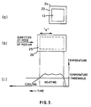
- Figure 4(a) illustrates the transfer of ink 39 from an ink layer 40 supported by a backing layer 41 in a first printing cycle.
- An area 42 is subjected to heating by the thermal print element 13 such that all the ink in the area 42 is capable of being transferred to the surface of the print receiving medium.
- Figure 4(b) illustrates the transfer of ink in the next printing cycle.
- Feeding of the medium together with the ribbon has now moved the area 42 relative to the printing element 13 and a new area 45 is in a position such that it is subjected to heating by the element 13.
- the portions 43, 44 in which ink was not successfully transferred to the medium in the first printing cycle lie within the new area 45 are subjected to heating again so that ink in at least one of these portions may be successfully transferred to the medium.
- successful transfer is effected in the area 44. Accordingly as shown in Figure 4(c), immediately prior to heating of the element 13 in a third printing cycle, the medium and ribbon have moved further past the element 13 and an area 46 is to be subjected to heating by the element 13 in the third printing cycle.
- the portion 43 lies within this area 46 and hence is subjected to heating again in the third printing cycle. Successful transfer of ink in the portion 43 is shown as having occurred by Figure 4(d). It will be appreciated that in these successive printing cycles ink may not be successfully transferred from other portions 47. However these will be subjected to repeated heating in successive later printing cycles to improve the transfer of ink from these portions.
- the successive printing cycles in which the areas of ribbon are subjected to successive heating will cause additional ink to be transferred in each cycle and hence any area intended to be printed but which has not received ink in one of the printing cycles is likely to receive ink in at least one of the succeeding cycles.
- the entire printed areas will have received ink from the ribbon and there will not be any un-inked portions of the printed areas.
- the printed area will be of a relatively uniform dense colour.
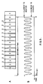
- the feed rate of the print receiving medium may be reduced as compared with the normal feed rate so as to result in most of the area to be printed being overprinted three times as illustrated in Figure 5(a).
- Figure 5(b) shows repetitive heating and cooling cycles of a print element. If the elongation of the print dot due to movement of the medium is ignored as shown in Figure 5(a) there would be narrow bands in the area which would be overprinted only twice. However the elongation due to this movement ensures that these bands are overprinted three times.
- Ribbon drive motors 53 for the winding and rewinding of the ribbon are controlled by the microprocessor 30. It is desirable to select the slower rate of feeding to cause successive overprinting as described hereinbefore only when the characteristics of the medium require such overprinting to be effected.
- apparatus arranged to permit slow feed rate with overprinting preferably has a default condition set up upon power up in which the high feed rate is selected.
- a user desires to print upon a medium which requires the slow feed rate with overprinting to attain printing of sufficient quality, the user selects this option by operation of a key button switch on the keyboard 33.
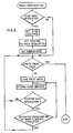
- Figure 6 is a flow chart illustrating a sequence of steps effected by a control device. At initiation of print preparation the microprocessor tests to determine whether the high resolution slow print rate has been selected by the user. If it has not been selected the control device continues with control of the printing device in the default condition.
- the control device selects a slow feed rate for the feed of the medium past the print head, sets a print pointer to high resolution print data, sets the ribbon rewinding control to a suitable ratio of forward and reverse feed (when a multi-strike ribbon is used) and then continues with control of the printing device.
- the purpose of setting the print pointer is that the same print data is used to selectively energise the print elements in a number of successive print cycles when effecting overprinting whereas when printing at the default low resolution the print data is used only once to selectively energise the print elements in a single print cycle.
- the setting of the pointer is used to control the utilisation of the print data according to the resolution selected.
Landscapes
- Electronic Switches (AREA)
- Impression-Transfer Materials And Handling Thereof (AREA)
Claims (10)
- Dispositif d'impression à transfert thermique, comprenant une pluralité d'éléments d'impression de points (13) disposés en une rangée, ces éléments d'impression de points pouvant être chauffés sélectivement pour transférer de l'encre provenant de zones sélectionnées d'un ruban d'encre à transfert thermique (49) sur un support de réception d'impression (16), afin d'imprimer les points correspondant à ces éléments, et des moyens (15) pour sélectionner des éléments de la pluralité d'éléments, caractérisé par des moyens (14, 35) pour chauffer de manière répétitive les éléments sélectionnés un certain nombre de fois de manière à transférer l'encre du ruban d'encre à transfert thermique (49) sur le support de réception d'impression (16), et par des moyens d'alimentation (17, 18) pour faire passer un support de réception d'impression avec le ruban d'encre à transfert thermique, devant la rangée des éléments d'impression, dans une direction transversale par rapport à la rangée et à une vitesse telle que le chauffage répété des éléments sélectionnés conduise à un chauffage répété des zones sélectionnées du ruban d'encre à transfert thermique, de manière à imprimer ainsi une pluralité de points en recouvrement (42, 45, 46).
- Dispositif d'impression à transfert thermique selon la revendication 1, caractérisé en outre par des moyens (17, 18, 52) pour fournir le support de réception d'impression (16) et le ruban d'encre à transfert thermique à une vitesse d'alimentation normale, et par des moyens de commande (30) actionnables sélectivement pour commander les moyens d'alimentation, de manière à fournir le support et le ruban d'encre à transfert thermique à une vitesse réduite, à laquelle le chauffage répété des éléments d'impression conduit au chauffage répété des zones du ruban d'encre à transfert thermique et à l'impression de points en recouvrement.
- Dispositif d'impression à transfert thermique selon la revendication 1 ou 2, caractérisé en outre en ce que le ruban d'encre à transfert thermique (49) est un ruban à une seule course, et en ce que le chauffage répété des éléments sélectionnés, et par conséquent le chauffage répété des zones sélectionnées du ruban d'encre à transfert thermique, amène l'encre (43, 44, 47) n'ayant pas été transférée à partir des zones sélectionnées pendant un chauffage des éléments sélectionnés (13), à être transférée à partir de ces zones sélectionnées dans un chauffage ultérieur de ces éléments sélectionnés et de ces zones sélectionnées.
- Dispositif d'impression à transfert thermique selon la revendication 1 ou 2, caractérisé en outre en ce que le ruban d'encre à transfert thermique (49) est un ruban à courses multiples, et en ce que le chauffage répété des éléments sélectionnés (13) amène l'encre (43, 44, 47) n'ayant pas été transférée à partir des zones sélectionnées du ruban d'encre à transfert thermique pendant un chauffage des éléments sélectionnés, à être transférée à partir de ces zones sélectionnées dans un chauffage ultérieur des éléments sélectionnés.
- Dispositif d'impression à transfert thermique selon l'une quelconque des revendications précédentes, caractérisé en outre par une mémoire tampon de données d'impression (15) pour stocker les données d'impression définissant les éléments d'impression sélectionnés (13) à exciter, par des moyens (30, 34) pour charger un bloc de données d'impression dans la mémoire tampon, par des moyens (14) répondant au bloc de données d'impression contenu dans la mémoire tampon (15) et actionnables par un signal de découpage (35) pour exciter'simultanément les éléments d'impression sélectionnés (13), et par des moyens de commande (30) pour générer une séquence des signaux de découpage de manière à effectuer l'excitation, dans une pluralité de cycles d'impression, des éléments d'impression sélectionnés (13) définis par le bloc de données d'impression chargé dans la mémoire tampon.
- Dispositif d'impression à transfert thermique selon l'une quelconque des revendications 1 à 5, comprenant des moyens de mémoire (15) pour stocker une pluralité de signaux de données d'impression correspondant respectivement à la pluralité d'éléments d'impression (13) et définissant certains, sélectionnés, de la pluralité d'éléments d'impression à chauffer pour imprimer des points dans des positions sélectionnées en une rangée sur le support de réception d'impression ; caractérisé en outre par des moyens d'entrée (37) actionnables pour sélectionner une impression à haute résolution et une impression à basse résolution, des moyens de commande (30) fonctionnant en réponse à la sélection de l'impression à haute résolution pour commander les moyens d'alimentation (17, 18) de manière à faire passer le support de réception (16) et le ruban (49) à une faible vitesse devant les éléments d'impression, à lire les signaux de données d'impression dans les moyens de mémoire (15) au cours d'un premier cycle d'impression afin de chauffer ceux, sélectionnés, des éléments d'impression pour produire le transfert de l'encre des zones sélectionnées de la couche d'encre chauffée par les éléments sélectionnés, vers le support de réception d'impression, de manière à imprimer les points sur ce support dans des positions correspondant aux éléments d'impression sélectionnés, et à lire de nouveau les signaux de données d'impression pour refaire chauffer ceux, sélectionnés, des éléments d'impression de manière à refaire chauffer les zones sélectionnées de la couche d'encre dans un second cycle d'impression afin de produire le transfert, aux points imprimés sur le support de réception d'impression dans le second cycle d'impression, de l'encre restant dans ces zones après le chauffage de celles-ci dans le premier cycle d'impression.
- Dispositif d'impression à transfert thermique selon l'une quelconque des revendications 1 à 5, comprenant des moyens de mémoire (15) pour stocker une pluralité de signaux de données d'impression correspondant respectivement à la pluralité d'éléments d'impression (13) et définissant ceux, sélectionnés, de la pluralité d'éléments d'impression à chauffer pour imprimer des points à des endroits sélectionnés dans une rangée sur le support de réception d'impression, et des moyens de commande (30) fonctionnant, dans un mode d'impression à basse résolution, pour commander les moyens d'alimentation (17, 18) de manière à faire passer le support de réception d'impression (16) et le ruban (49) à grande vitesse devant les éléments d'impression (11) et, dans un premier cycle d'impression, à lire dans les moyens de mémoire (15) les signaux de données d'impression concernant les premiers points à imprimer dans une première rangée sur le support de réception d'impression, afin de produire le chauffage des premiers, sélectionnés, des éléments d'impression, pour produire le transfert de l'encre à partir des premières zones de la couche d'encre chauffées par les premiers, sélectionnés, des éléments d'impression, de manière à imprimer les premiers points dans la première rangée sur le support de réception d'impression, puis, dans un second cycle d'impression, à lire dans les moyens de mémoire (15) les signaux de données d'impression concernant des seconds points à imprimer dans une seconde rangée sur le support de réception d'impression, afin de produire le chauffage des seconds, sélectionnés, des éléments d'impression, pour produire le transfert de l'encre à partir des secondes zones de la couche d'encre chauffées par les seconds, sélectionnés, des éléments d'impression, de manière à imprimer les seconds points dans la seconde rangée sur le support de réception d'impression, caractérisé en outre par des moyens d'entrée (37) fonctionnant pour sélectionner le mode d'impression à basse résolution ou le mode d'impression à haute résolution, les moyens de commande (30) fonctionnant en réponse à la sélection du mode d'impression à haute résolution pour commander les moyens d'alimentation (17, 18) de manière à faire passer le support de réception d'impression (16) et le ruban (49), à une faible vitesse inférieure à la grande vitesse, devant les éléments d'impression, à lire les signaux de données d'impression dans les moyens de mémoire (15) au cours d'un premier cycle d'impression pour chauffer les premiers, sélectionnés, des éléments d'impression afin de produire le transfert de l'encre des premières zones de la couche d'encre chauffées par les premiers éléments sélectionnés, vers le support de réception d'impression de manière à imprimer les premiers points sur ce support en des endroits correspondant aux premiers éléments d'impression sélectionnés, et à lire de nouveau les signaux de données d'impression pour refaire chauffer ceux, sélectionnés, des éléments d'impression, de manière à refaire chauffer les premières zones sélectionnées de la couche d'encre dans un second cycle d'impression, afin de produire le transfert aux premiers points imprimés sur le support de réception d'impression, dans le second cycle d'impression, de l'encre restant dans les premières zones après le chauffage de celles-ci dans le premier cycle d'impression.
- Procédé d'impression à transfert thermique dans lequel de l'encre est transférée d'une couche contenant de l'encre (40) d'un ruban de transfert thermique (49), sur un support de réception d'impression (16), par chauffage de zones sélectionnées (42, 45, 46) du ruban, caractérisé par les étapes consistant à chauffer de manière répétitive un certain nombre de fois chacune des zones sélectionnées (42, 45, 46) pour s'assurer que le transfert requis de l'encre (40) est effectué de manière à produire une impression de haute qualité sur le support (16).
- Procédé d'impression à transfert thermique selon la revendication 8, dans lequel la couche contenant de l'encre (40) du ruban d'encre à transfert thermique (49), est amenée en contact avec la surface du support de réception d'impression (16) et entraînée avec ce support de réception d'impression pour passer devant des éléments d'impression chauffables sélectivement (13) d'une tête d'impression thermique, et dans lequel certains, sélectionnés, des éléments d'impression (13) sont chauffés pour faire chauffer des zones sélectionnées de la couche contenant de l'encre (40) de manière à transférer l'encre de ces zones sélectionnées de la couche d'encre devant être reçues par des zones correspondantes de la surface du support de réception d'impression, caractérisé en ce qu'on refait chauffer ceux, sélectionnés, des éléments d'impression (13) pour refaire chauffer une partie au moins de chaque zone sélectionnée (42, 45, 46) de la couche d'encre (40), de manière à produire un autre transfert de l'encre de ces zones vers les zones correspondantes du support de réception d'impression (16).
- Procédé d'impression à transfert thermique selon la revendication 8, dans lequel une couche contenant de l'encre (40) d'un ruban d'encre à transfert thermique (49) est amenée en contact avec la surface d'un support de réception d'impression (16) et entraînée avec ce support de réception d'impression pour passer devant des éléments d'impression chauffables sélectivement (13) d'une tête d'impression thermique, tandis que, dans un premier cycle d'impression, ceux sélectionnés des éléments d'impression (13) sont chauffés pour faire chauffer des zones sélectionnées (42) de la couche contenant de l'encre (40), de manière à produire le transfert de l'encre de ces zones sélectionnées de la couche d'encre vers les zones correspondantes de la surface du support de réception d'impression, et dans lequel, du fait d'une adhérence défectueuse de l'encre à la surface du support de réception d'impression, des parties des zones correspondantes ne reçoivent pas d'encre, caractérisé en ce que, dans un second cycle d'impression, on refait chauffer ceux sélectionnés des éléments d'impression (13) pour refaire chauffer une partie de chaque zone sélectionnée (42) de la couche d'encre (40), afin de produire le transfert de l'encre (43, 44) restant dans ces zones sélectionnées, sur les parties des zones correspondantes du support de réception d'impression.
Applications Claiming Priority (2)
| Application Number | Priority Date | Filing Date | Title |
|---|---|---|---|
| GB8928990 | 1989-12-22 | ||
| GB898928990A GB8928990D0 (en) | 1989-12-22 | 1989-12-22 | Thermal transfer printing |
Publications (2)
| Publication Number | Publication Date |
|---|---|
| EP0434340A1 EP0434340A1 (fr) | 1991-06-26 |
| EP0434340B1 true EP0434340B1 (fr) | 1995-06-28 |
Family
ID=10668373
Family Applications (1)
| Application Number | Title | Priority Date | Filing Date |
|---|---|---|---|
| EP90313769A Expired - Lifetime EP0434340B1 (fr) | 1989-12-22 | 1990-12-17 | Méthode d'impression à transfert thermique |
Country Status (4)
| Country | Link |
|---|---|
| US (1) | US5357270A (fr) |
| EP (1) | EP0434340B1 (fr) |
| DE (1) | DE69020522T2 (fr) |
| GB (1) | GB8928990D0 (fr) |
Cited By (1)
| Publication number | Priority date | Publication date | Assignee | Title |
|---|---|---|---|---|
| EP0978386A2 (fr) | 1998-08-06 | 2000-02-09 | Francotyp-Postalia AG & Co. | Imprimante par transfert thermique |
Families Citing this family (14)
| Publication number | Priority date | Publication date | Assignee | Title |
|---|---|---|---|---|
| US5319392A (en) † | 1992-12-21 | 1994-06-07 | Pitney Bowes Inc. | Thermal printing apparatus having variable speed printing |
| GB9410273D0 (en) * | 1994-05-20 | 1994-07-13 | Prestek Ltd | Printing apparatus |
| AU756087B2 (en) | 1998-01-12 | 2003-01-02 | Easyprint A/S | A method of thermal printing and a thermal printer |
| US6354753B1 (en) * | 1998-01-12 | 2002-03-12 | Easyprint Aps | Method of thermal printing and a thermal printer |
| US6607318B2 (en) | 1998-01-12 | 2003-08-19 | Easyprint A/S | Thermal printer |
| US6579020B2 (en) | 1998-01-12 | 2003-06-17 | Easyprint A/S | Thermal printer |
| US6431774B1 (en) * | 1999-02-19 | 2002-08-13 | Seiko Epson Corporation | Printer, control method for the same, and data storage medium for recording the control method |
| EP2255969B1 (fr) | 2000-09-11 | 2011-06-01 | Zipher Limited | Appareil d'impression |
| GB0105067D0 (en) * | 2001-03-01 | 2001-04-18 | Zipher Ltd | Improvements in printing |
| US20070172130A1 (en) * | 2006-01-25 | 2007-07-26 | Konstantin Zuev | Structural description of a document, a method of describing the structure of graphical objects and methods of object recognition. |
| GB2448302B (en) | 2007-03-07 | 2009-04-08 | Zipher Ltd | Tape drive |
| GB2448301B (en) * | 2007-03-07 | 2009-03-11 | Zipher Ltd | Tape drive |
| GB2448305B (en) * | 2007-03-07 | 2009-03-11 | Zipher Ltd | Tape drive |
| EP2134549B1 (fr) * | 2007-03-31 | 2014-11-19 | Videojet Technologies, Inc. | Dérouleur de bande |
Family Cites Families (7)
| Publication number | Priority date | Publication date | Assignee | Title |
|---|---|---|---|---|
| JPS59141872A (ja) * | 1983-02-02 | 1984-08-14 | Fuji Xerox Co Ltd | 感熱記録装置 |
| GB2144081B (en) * | 1983-07-23 | 1987-10-28 | Pa Consulting Services | Postal franking machines |
| JPS6124467A (ja) * | 1984-07-13 | 1986-02-03 | Nec Corp | 熱転写プリンタ |
| JPS61206663A (ja) * | 1985-03-12 | 1986-09-12 | Tokyo Electric Co Ltd | サ−マルプリンタにおける印字方法 |
| US4739343A (en) * | 1986-05-09 | 1988-04-19 | Pitney Bowes Inc. | Thermal printing system for postage meter mailing machine application |
| GB8623061D0 (en) * | 1986-09-25 | 1986-10-29 | Roneo Alcatel Ltd | Franking machine |
| JPS63317362A (ja) * | 1987-06-19 | 1988-12-26 | Shinko Electric Co Ltd | サ−マルプリンタの印刷方法 |
-
1989
- 1989-12-22 GB GB898928990A patent/GB8928990D0/en active Pending
-
1990
- 1990-12-17 EP EP90313769A patent/EP0434340B1/fr not_active Expired - Lifetime
- 1990-12-17 DE DE69020522T patent/DE69020522T2/de not_active Expired - Fee Related
-
1992
- 1992-09-30 US US07/953,771 patent/US5357270A/en not_active Expired - Lifetime
Cited By (2)
| Publication number | Priority date | Publication date | Assignee | Title |
|---|---|---|---|---|
| EP0978386A2 (fr) | 1998-08-06 | 2000-02-09 | Francotyp-Postalia AG & Co. | Imprimante par transfert thermique |
| DE19835544C1 (de) * | 1998-08-06 | 2000-10-26 | Francotyp Postalia Gmbh | Thermotransfer-Druckvorrichtung |
Also Published As
| Publication number | Publication date |
|---|---|
| GB8928990D0 (en) | 1990-02-28 |
| US5357270A (en) | 1994-10-18 |
| EP0434340A1 (fr) | 1991-06-26 |
| DE69020522T2 (de) | 1996-04-04 |
| DE69020522D1 (de) | 1995-08-03 |
Similar Documents
| Publication | Publication Date | Title |
|---|---|---|
| EP0434340B1 (fr) | Méthode d'impression à transfert thermique | |
| US4746234A (en) | Relating to postal franking machines | |
| EP0315384B1 (fr) | Dispositif d'avance pour ruban d'impression thermique | |
| CA1179887A (fr) | Dispositif de guidage de ruban de correction de la temperature de levee | |
| EP0493942B1 (fr) | Dispositif d'avance pour ruban encreur | |
| JPS6168687A (ja) | 固定及び可変情報をプリントするサーマルプリント機構 | |
| EP0170133B1 (fr) | Mesure de correction répétitive pour enlever des caractères imprimés thermiquement | |
| US4851861A (en) | Thermal transfer recording device | |
| US5682504A (en) | Driving technique for printhead of thermal printer to improve print quality | |
| US4737924A (en) | Dot matrix type serial printer | |
| US4669897A (en) | Dot matrix printer capable of varying character size | |
| EP0202866A1 (fr) | Imprimante avec moyen pour alimentation supplémentaire du ruban encreur en cas de besoin | |
| US5166883A (en) | Franking machine | |
| US4542997A (en) | Method of and apparatus for printing colored patterns | |
| CA1212582A (fr) | Systeme et methode d'impression par transfert de chaleur a ruban resistif | |
| US5005993A (en) | Electrothermal printer with a resistive ink ribbon and differing resistance current return paths | |
| US6518992B1 (en) | Thermal line printer and a method of driving the same | |
| EP0165563B1 (fr) | Imprimante à tête thermique | |
| EP0054709B1 (fr) | Méthodes pour la correction d'erreurs d'impression pendant l'impression | |
| EP0183465A1 (fr) | Procédé de correction de frappe pour machine à écrire | |
| JPS59161968A (ja) | サ−マルプリンタ | |
| US4586055A (en) | Method and apparatus for printing colored patterns | |
| JP4320478B2 (ja) | プリンタ及び印刷方法 | |
| EP0113423B1 (fr) | Imprimante par percussion | |
| JP2589481B2 (ja) | 記録ヘツドの駆動方法 |
Legal Events
| Date | Code | Title | Description |
|---|---|---|---|
| PUAI | Public reference made under article 153(3) epc to a published international application that has entered the european phase |
Free format text: ORIGINAL CODE: 0009012 |
|
| AK | Designated contracting states |
Kind code of ref document: A1 Designated state(s): DE FR GB |
|
| 17P | Request for examination filed |
Effective date: 19911211 |
|
| RAP1 | Party data changed (applicant data changed or rights of an application transferred) |
Owner name: NEOPOST LIMITED |
|
| 17Q | First examination report despatched |
Effective date: 19930716 |
|
| GRAA | (expected) grant |
Free format text: ORIGINAL CODE: 0009210 |
|
| AK | Designated contracting states |
Kind code of ref document: B1 Designated state(s): DE FR GB |
|
| REF | Corresponds to: |
Ref document number: 69020522 Country of ref document: DE Date of ref document: 19950803 |
|
| ET | Fr: translation filed | ||
| PLBE | No opposition filed within time limit |
Free format text: ORIGINAL CODE: 0009261 |
|
| STAA | Information on the status of an ep patent application or granted ep patent |
Free format text: STATUS: NO OPPOSITION FILED WITHIN TIME LIMIT |
|
| 26N | No opposition filed | ||
| REG | Reference to a national code |
Ref country code: GB Ref legal event code: IF02 |
|
| PGFP | Annual fee paid to national office [announced via postgrant information from national office to epo] |
Ref country code: DE Payment date: 20051212 Year of fee payment: 16 |
|
| PGFP | Annual fee paid to national office [announced via postgrant information from national office to epo] |
Ref country code: FR Payment date: 20051219 Year of fee payment: 16 |
|
| PGFP | Annual fee paid to national office [announced via postgrant information from national office to epo] |
Ref country code: GB Payment date: 20051222 Year of fee payment: 16 |
|
| PG25 | Lapsed in a contracting state [announced via postgrant information from national office to epo] |
Ref country code: DE Free format text: LAPSE BECAUSE OF NON-PAYMENT OF DUE FEES Effective date: 20070703 |
|
| GBPC | Gb: european patent ceased through non-payment of renewal fee |
Effective date: 20061217 |
|
| REG | Reference to a national code |
Ref country code: FR Ref legal event code: ST Effective date: 20070831 |
|
| PG25 | Lapsed in a contracting state [announced via postgrant information from national office to epo] |
Ref country code: GB Free format text: LAPSE BECAUSE OF NON-PAYMENT OF DUE FEES Effective date: 20061217 |
|
| PG25 | Lapsed in a contracting state [announced via postgrant information from national office to epo] |
Ref country code: FR Free format text: LAPSE BECAUSE OF NON-PAYMENT OF DUE FEES Effective date: 20070102 |