EP0183465A1 - Procédé de correction de frappe pour machine à écrire - Google Patents
Procédé de correction de frappe pour machine à écrire Download PDFInfo
- Publication number
- EP0183465A1 EP0183465A1 EP85308394A EP85308394A EP0183465A1 EP 0183465 A1 EP0183465 A1 EP 0183465A1 EP 85308394 A EP85308394 A EP 85308394A EP 85308394 A EP85308394 A EP 85308394A EP 0183465 A1 EP0183465 A1 EP 0183465A1
- Authority
- EP
- European Patent Office
- Prior art keywords
- erasing
- correction tape
- impression
- misprint
- correction
- Prior art date
- Legal status (The legal status is an assumption and is not a legal conclusion. Google has not performed a legal analysis and makes no representation as to the accuracy of the status listed.)
- Granted
Links
- 238000012937 correction Methods 0.000 title claims abstract description 97
- 238000000034 method Methods 0.000 title claims abstract description 18
- 238000004804 winding Methods 0.000 description 5
- 238000012546 transfer Methods 0.000 description 3
- 239000000853 adhesive Substances 0.000 description 2
- 230000001070 adhesive effect Effects 0.000 description 2
- 230000002596 correlated effect Effects 0.000 description 2
- 238000012986 modification Methods 0.000 description 2
- 230000004048 modification Effects 0.000 description 2
- 230000003466 anti-cipated effect Effects 0.000 description 1
- 238000007796 conventional method Methods 0.000 description 1
- 230000000994 depressogenic effect Effects 0.000 description 1
Images


Classifications
-
- B—PERFORMING OPERATIONS; TRANSPORTING
- B41—PRINTING; LINING MACHINES; TYPEWRITERS; STAMPS
- B41J—TYPEWRITERS; SELECTIVE PRINTING MECHANISMS, i.e. MECHANISMS PRINTING OTHERWISE THAN FROM A FORME; CORRECTION OF TYPOGRAPHICAL ERRORS
- B41J29/00—Details of, or accessories for, typewriters or selective printing mechanisms not otherwise provided for
- B41J29/26—Devices, non-fluid media or methods for cancelling, correcting errors, underscoring or ruling
- B41J29/36—Devices, non-fluid media or methods for cancelling, correcting errors, underscoring or ruling for cancelling or correcting errors by overprinting
Definitions
- the present invention relates to a typewriter misprint correction method.
- Typewriter carriages with print erasing function is provided with a typing head, a printing ink ribbon and an adhesive correction tape.
- the ink ribbon is shifted up to printing position, and a type is impressed on the paper through the ink ribbon.
- the carriage moves one character to the right (spacing) for each type impression.
- the carriage is moved back to-the left (backspacing) to misprint position.
- the correction tape is then shifted u p to printing p osi- tion, and the misprint type is selected and impressed on the paper through the correction tape. Misprint ink is thus lifted from the papar on to the adhesive surface of the correction tape, erasing the misprint.
- Another object of the present invention is to provide a typewriter misprint correction method in which a prescribed length of correction tape is fed after the initial erasing impression to avoid ink transfer from correction tape.to the paper for complete misprint erasure.
- Additional object of the present invention is to provide a typewriter misprint correction method in which correction tape is fed for each of multiple erasing impressions for complete misprint.erasure with minimum ink transfer from correction tape to paper.
- a prescribed length of correction tape is fed after the initial erasing impression in a typewriter misprint correction method in which a misprint is erased by multiple erasing impressions through correction tape.
- Fig. 1 is a perspective view of a typewriter .carriage according - to the present invention
- Fig. 2 is a plan view showing a correction tape winding reel sprocket wheel
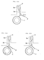
- Figs. 3 (a) through 3 (c) are plan views showing the sprocket wheel driving mechanism
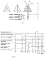
- Fig. 4 shows carriage movement for erasing impression
- Fig. 5 is an erasing operation time chart for an embodiment of the present invention
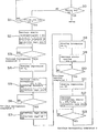
- Fig. 6 is a flow chart of the erasing operation in Fig. 5
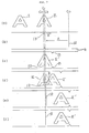
- Fig. 7 shows an erasing operation for another embodiment of the invention
- Fig. 8 is a time chart of the erasing operation in Fig. 7.
- a typewriter carriage related to the present invention is partially shown, in perspective, in Fig. 1.
- (4) is the shifter. Printing ink ribbon or correction tape is shifted up to printing position by upward movement of the shifter (4).
- (5) is a correction tape winding reel under which a sprocket wheel (1) is coaxially mounted, as shown in Fig. 2.
- the upward shift of the correction tape for erasing operation actuates driving lever (2) of the sprocket wheel (1), moving it in the direction indicated by the arrow, causing sprocket wheel (1) or correction tape winding reel (5) to rotate to feed the prescribed length of correction tape.
- a mechanism is provided to selectively release the correlated correction tape feed operation.
- switching solenoid (3) including electro-magnetic coil is positioned perpendicularly to driving lever (2) driving direction, on the opposite side of the sprocket wheel (1).
- the driving lever (2) is connected through a rotary connecting rod (3b) to a switching solenoid cylinder (3a).
- correction tape has not shifted up and switching solenoid (3) is turned OFF.
- Fig. 3 (b) correction tape is shifted up and driving lever (2) is actuated, turning sprocket wheel (1) .for correction tape feed.
- correction tape is shifted up and driver lever (2) is driven when switching solenoid (3) is switched on.
- the driving lever (2) which is moved toward the excited switching solenoid (3), disengages from sprocket wheel (1). As a result, sprocket wheel (1) does not rotate and, therefore, correction tape is not fed.
- Figure 4 shows carriage center positions for three type impression operations for letter "A” erasure.
- the carriage backspaces from the subsequent printing position “C 0 " to position “C l “, where an erasing impression is conducted, and moves to position "C Z " and then to "C 3 " for additional erasing impressions.
- step S 1 When correction key is depressed at step So, operation proceeds from step S 1 to step S 2 , where the carriage backspaces from “Co” to “C 1 ". Simultaneously, switching solenoid (3) is turned ON, shifting correction tape up. At this time correction tape is not fed due to switching solenoid (3) actuation.
- step S 3 When the above carriage backspacing is completed, operation proceeds from step S 3 to step S 4 , where an erasing impression is conducted at position "C 1 ". In step Ss, the carriage further backspaces from “C 1 " to “C 2 " and switching solenoid (3) is turned OFF, shifting correction tape down.
- step S 6 When the above carriage backspacing is completed, operation proceeds from step S 6 to step S 7 , where correction tape is again shifted up.
- step S 8 An erasing impression is conducted at position "C z " in step S 8 , after which the carriage starts moving from “C 2 " to “C3” in step S 9 .
- step S 10 the final erasing impression is conducted position "C 3 ".
- step S 12 the carriage starts backspacing from position "C 3 " to position "C i " and correction tape is shifted down.
- backspacing is completed, operation returns from step Si 3 to initial step So and erasing operation ends.
- correction tape is not fed before initial erasing impression but after it.
- the second and the third erasing impressions are conducted using fresh correction tape. Accordingly, correction tape used for the second and the third erasing impressions will be used for the first erasing impression in the subsequent correction operation. It might be anticipated, therefore, that ink adhering to the correction tape from previous correction operation will be transferred onto the paper in the subsequent correction operation. In fact, only a small portion of a character remains unerased after the first impression and, therefore, only a small amount of ink adheres to the correction tape in the second and third erasing impressions. Ink transfer from correction tape onto paper is therefore negligible. Thus, according to this embodiment of the present invention, character erasing performance is improved without increasing correction tape feed.
- a mechanism is provided for selectively feeding correction tape only after the first erasing impression so that second and subsequent erasing impressions are performed with fresh correction tape. Erasing performance can thus be improved without increasing correction tape feed.
- Correction tape is fed only once after the first erasing impression in the above embodiment. Alternatively, it may be fed after the second impression or after any subsequent impressions. It may also be fed by a prescribed amount two or more times between erasing impressions.
- erasing impression is conducted N times for each character and a prescribed length of correction tape is fed for each type impression.
- Correction tape feed length for each erasing impression is 1/N of the tape length required to erase a single character.
- Figure 7 shows the erasing operation for the second embodiment of the invention, in which three erasing impression are conducted for a single character and correction tape is fed by 1/3 the conventional tape feed "P" (length required to erase one character) for each erasing impression.
- Figure 7 (a) shows characters I and II printed on paper. "C o " indicates the subsequent printing position, namely carriage center position.
- (10) is the correction tape
- (12) is the carriage center position for printing or erasing operation.
- Correction tape (10) is provided with a notch (13) to indicate tape feed length.
- Figure 7 (b) shows carriage center position before erasing operation.
- the notch (13) is located at "Ci”
- carriage center (12) is positioned at "C o ".
- the carriage center (12) backspaces, as indicated by arrow “A”, to center position "Ci” of character II, and correction tape (10) is shifted up to erasing position, namely misprint position (not shown in Fig. 7).
- correction tape (10) is fed by the length P/3 to the right, as indicated by arrow "B”.
- Figure 7 (c) shows conditions after the first erasing impression has been made, with the ink (indicated by II') from character II adhering to the correction tape.
- Figure 7 (d) shows correction tape (10) being fed to the right.
- the character shown in dotted line, identified by III, indicates unerased character II under correction tape (10).
- the second erasing impression is conducted. In this impression, only the ink portion IV at the intersection of the characters II' and III may be transferred from correction tape (10) onto the paper.
- Figure 8 is an erasing operation time chart in which the timing of each operation step (b) through (f) shown in Fig. 7 is marked.
- correction tape is shifted up and fed for each erasing impression.
- Sprocket wheel (2a) has three times as many teeth as the conventional sprocket wheel but has the same diameter; thus correction tape is fed by 1/3 the conventional feed length (required to erase a character) for each erasing impression.
- correction tape winding reel (5) rotates at a constant rate when feeding correction tape.
- correction tape winding reel diameter increases as correction tape is fed and wound.
- erasing impression is conducted as "N" times for each character and correction tape is fed by 1/N the total correction tape feed length "P" (required to erase a single character) for each erasing impression.
- P the total correction tape feed length
- erasing impression is made two or more times for a single character and correction tape is fed by a prescribed length after (or before) at least one erasing impression for complete misprint erasure.
- a typing or printing correction method in which a misprint is over-typed or over-printed a plurality of times using a misprint obliteration or lifting medium, characterised in that such over-typing or over-printing is carried out with slightly varying offsets relative to the misprint.
- a typewriter or printer having means for over-typing or over-printing a misprint a plurality of times using an obliteration or lifting medium characterised by means to vary the offset of the overtyping or overprinting slightly and automatically relative to the misprint between the over-printing or over-typing operations.
- a typing or printing correction method in which a misprint is over-typed or over-printed a plurality of times through the medium of an obliteration or lifting tape, characterised in that the tape is fed at least once after the first time, but not between the last time and a first time of a subsequent over-typing or over-printing operation.
- a typewriter or printer having means for over-typing or over-printing a misprint a plurality of times through the medium of an obliteration or lifting tape, characterised by means to feed the tape automatically at least once after the first time, but not between the last time and a first time of a subsequent over-typing or over-printing operation.
- a typing or printing correction method in which a misprint is over-typed or over-printed a plurality of times through the medium of an obliteration or lifting tape, characterised in that the tape is advanced each time so that the total advance for said plurality of times is equal or slightly greater than the character width.
- a typewriter or printer having means for over-typing or over-printing a misprint a plurality of times through the medium of an obliteration or lifting tape, characterised by means to advance the tape automatically each time so that the total advance for said plurality of times is equal to or slightly greater than the character width.
Landscapes
- Accessory Devices And Overall Control Thereof (AREA)
Applications Claiming Priority (4)
| Application Number | Priority Date | Filing Date | Title |
|---|---|---|---|
| JP25099884A JPS61127379A (ja) | 1984-11-27 | 1984-11-27 | タイプライタ−における印字修正方法 |
| JP250998/84 | 1984-11-27 | ||
| JP25099784A JPS61127378A (ja) | 1984-11-27 | 1984-11-27 | タイプライタ−における印字修正方法 |
| JP250997/84 | 1984-11-27 |
Publications (2)
| Publication Number | Publication Date |
|---|---|
| EP0183465A1 true EP0183465A1 (fr) | 1986-06-04 |
| EP0183465B1 EP0183465B1 (fr) | 1989-05-17 |
Family
ID=26540015
Family Applications (1)
| Application Number | Title | Priority Date | Filing Date |
|---|---|---|---|
| EP85308394A Expired EP0183465B1 (fr) | 1984-11-27 | 1985-11-18 | Procédé de correction de frappe pour machine à écrire |
Country Status (4)
| Country | Link |
|---|---|
| US (1) | US4708505A (fr) |
| EP (1) | EP0183465B1 (fr) |
| CA (1) | CA1256817A (fr) |
| DE (1) | DE3570212D1 (fr) |
Families Citing this family (4)
| Publication number | Priority date | Publication date | Assignee | Title |
|---|---|---|---|---|
| DE3743414A1 (de) * | 1986-12-26 | 1988-07-07 | Canon Kk | Aufzeichnungseinrichtung |
| JPS63242583A (ja) * | 1987-03-28 | 1988-10-07 | Brother Ind Ltd | 文字消去可能な印字装置 |
| JPH01171971A (ja) * | 1987-12-28 | 1989-07-06 | Sharp Corp | 電子タイプライタのコレクション制御方法 |
| JPH026168A (ja) * | 1988-06-24 | 1990-01-10 | Brother Ind Ltd | 印字装置 |
Citations (3)
| Publication number | Priority date | Publication date | Assignee | Title |
|---|---|---|---|---|
| CH632704A5 (en) * | 1977-11-21 | 1982-10-29 | Ibm | Ink-ribbon and correction-ribbon transporting device for electric typewriters |
| CH635030A5 (de) * | 1978-01-30 | 1983-03-15 | Ibm | Verfahren und vorrichtung zum tilgen unerwuenschter zeichen in aufschlagdruckern. |
| GB2120604A (en) * | 1982-03-19 | 1983-12-07 | Canon Kk | Erasing typed indicia |
Family Cites Families (7)
| Publication number | Priority date | Publication date | Assignee | Title |
|---|---|---|---|---|
| CH488228A (de) * | 1968-07-13 | 1970-03-31 | Olympia Werke Ag | Vorrichtung zum Schalten eines Farb- bzw. Kohlebandes für rechnende Maschinen |
| US4307971A (en) * | 1978-01-30 | 1981-12-29 | International Business Machines Corporation | Sideshift erase apparatus and method for impact printers |
| DE3014769A1 (de) * | 1980-04-17 | 1981-10-22 | Olympia Werke Ag, 2940 Wilhelmshaven | Verfahren zur erzeugung von soch teilweise ueberdeckenden schriftzeichen auf einem aufzeichnungstraeger in schreib- o.ae. brueomaschinen |
| JPS5856883A (ja) * | 1981-09-30 | 1983-04-04 | Canon Inc | 印字装置 |
| JPS58158286A (ja) * | 1982-03-15 | 1983-09-20 | Fujitsu Ltd | リボンシフトによる印字方式 |
| JPS58194593A (ja) * | 1982-05-11 | 1983-11-12 | Nec Corp | インパクトドツトプリンタ |
| JPS5939589A (ja) * | 1982-08-30 | 1984-03-03 | インタ−ナシヨナル ビジネス マシ−ンズ コ−ポレ−シヨン | サ−マル・プリンタ |
-
1985
- 1985-11-13 CA CA000495239A patent/CA1256817A/fr not_active Expired
- 1985-11-18 DE DE8585308394T patent/DE3570212D1/de not_active Expired
- 1985-11-18 EP EP85308394A patent/EP0183465B1/fr not_active Expired
- 1985-11-25 US US06/801,584 patent/US4708505A/en not_active Expired - Lifetime
Patent Citations (3)
| Publication number | Priority date | Publication date | Assignee | Title |
|---|---|---|---|---|
| CH632704A5 (en) * | 1977-11-21 | 1982-10-29 | Ibm | Ink-ribbon and correction-ribbon transporting device for electric typewriters |
| CH635030A5 (de) * | 1978-01-30 | 1983-03-15 | Ibm | Verfahren und vorrichtung zum tilgen unerwuenschter zeichen in aufschlagdruckern. |
| GB2120604A (en) * | 1982-03-19 | 1983-12-07 | Canon Kk | Erasing typed indicia |
Also Published As
| Publication number | Publication date |
|---|---|
| DE3570212D1 (en) | 1989-06-22 |
| EP0183465B1 (fr) | 1989-05-17 |
| CA1256817A (fr) | 1989-07-04 |
| US4708505A (en) | 1987-11-24 |
Similar Documents
| Publication | Publication Date | Title |
|---|---|---|
| EP0982146A3 (fr) | Imprimante, medium de stockage pour des programmes de commande d'impression et méthode d'impression | |
| EP0434340B1 (fr) | Méthode d'impression à transfert thermique | |
| EP0183465B1 (fr) | Procédé de correction de frappe pour machine à écrire | |
| US4700200A (en) | Thermal printer | |
| US5025725A (en) | Double paper cut system for printer mechanism | |
| SE438983B (sv) | Metod och anordning for radering av tryckta tecken | |
| EP0021737A1 (fr) | Procédé et dispositif pour maintenir la tension d'un ruban et son application à une machine à écrire | |
| US4585362A (en) | One-touch character correction and replacement system | |
| US4647238A (en) | Printer with a control for feeding disposable ribbon with minimum waste length | |
| JP4320478B2 (ja) | プリンタ及び印刷方法 | |
| JPS60198282A (ja) | タイプライタ | |
| US4707703A (en) | Method of performing thermal multicolor printing | |
| JPS59207276A (ja) | サ−マルプリンタ | |
| GB2201640A (en) | Recording apparatus | |
| JPS58110256A (ja) | 印字装置 | |
| JPS6131280A (ja) | 印字装置 | |
| JP3352250B2 (ja) | プリンタの印字方法 | |
| JPS6366673B2 (fr) | ||
| JPS61283594A (ja) | サ−マルプリンタの記録方法 | |
| JPS61258783A (ja) | 熱転写式シリアル・プリンタ | |
| JP2602004Y2 (ja) | 粘着テープ印字装置 | |
| JPS5996981A (ja) | ワイヤドツトプリンタにおける印字方法 | |
| JPH081091Y2 (ja) | 貼着テープ印字装置 | |
| JPS61284474A (ja) | 電子タイプライタ | |
| JPS6056575A (ja) | ハイブリツドプリンタ |
Legal Events
| Date | Code | Title | Description |
|---|---|---|---|
| PUAI | Public reference made under article 153(3) epc to a published international application that has entered the european phase |
Free format text: ORIGINAL CODE: 0009012 |
|
| AK | Designated contracting states |
Kind code of ref document: A1 Designated state(s): DE GB IT |
|
| 17P | Request for examination filed |
Effective date: 19860929 |
|
| 17Q | First examination report despatched |
Effective date: 19880205 |
|
| ITF | It: translation for a ep patent filed | ||
| GRAA | (expected) grant |
Free format text: ORIGINAL CODE: 0009210 |
|
| AK | Designated contracting states |
Kind code of ref document: B1 Designated state(s): DE GB IT |
|
| REF | Corresponds to: |
Ref document number: 3570212 Country of ref document: DE Date of ref document: 19890622 |
|
| PLBE | No opposition filed within time limit |
Free format text: ORIGINAL CODE: 0009261 |
|
| STAA | Information on the status of an ep patent application or granted ep patent |
Free format text: STATUS: NO OPPOSITION FILED WITHIN TIME LIMIT |
|
| 26N | No opposition filed | ||
| ITTA | It: last paid annual fee | ||
| REG | Reference to a national code |
Ref country code: GB Ref legal event code: IF02 |
|
| PGFP | Annual fee paid to national office [announced via postgrant information from national office to epo] |
Ref country code: DE Payment date: 20041111 Year of fee payment: 20 |
|
| PGFP | Annual fee paid to national office [announced via postgrant information from national office to epo] |
Ref country code: GB Payment date: 20041117 Year of fee payment: 20 |
|
| PG25 | Lapsed in a contracting state [announced via postgrant information from national office to epo] |
Ref country code: GB Free format text: LAPSE BECAUSE OF EXPIRATION OF PROTECTION Effective date: 20051117 |
|
| REG | Reference to a national code |
Ref country code: GB Ref legal event code: PE20 |