EP0434422A1 - Fabrication de mètre-rubans - Google Patents
Fabrication de mètre-rubans Download PDFInfo
- Publication number
- EP0434422A1 EP0434422A1 EP90314006A EP90314006A EP0434422A1 EP 0434422 A1 EP0434422 A1 EP 0434422A1 EP 90314006 A EP90314006 A EP 90314006A EP 90314006 A EP90314006 A EP 90314006A EP 0434422 A1 EP0434422 A1 EP 0434422A1
- Authority
- EP
- European Patent Office
- Prior art keywords
- strip
- tape
- printing
- support
- Prior art date
- Legal status (The legal status is an assumption and is not a legal conclusion. Google has not performed a legal analysis and makes no representation as to the accuracy of the status listed.)
- Granted
Links
- 238000004519 manufacturing process Methods 0.000 title description 4
- 238000007639 printing Methods 0.000 claims description 36
- 239000000463 material Substances 0.000 claims description 13
- 238000000034 method Methods 0.000 claims description 13
- 230000008569 process Effects 0.000 claims description 9
- 238000012544 monitoring process Methods 0.000 claims description 7
- 230000001105 regulatory effect Effects 0.000 claims description 2
- 230000000694 effects Effects 0.000 description 3
- 230000033228 biological regulation Effects 0.000 description 2
- 230000004044 response Effects 0.000 description 2
- 239000000758 substrate Substances 0.000 description 2
- 229910000831 Steel Inorganic materials 0.000 description 1
- 230000015572 biosynthetic process Effects 0.000 description 1
- 230000008859 change Effects 0.000 description 1
- 230000007423 decrease Effects 0.000 description 1
- 230000001419 dependent effect Effects 0.000 description 1
- 239000000975 dye Substances 0.000 description 1
- 238000005516 engineering process Methods 0.000 description 1
- 239000004744 fabric Substances 0.000 description 1
- 239000011152 fibreglass Substances 0.000 description 1
- 238000007641 inkjet printing Methods 0.000 description 1
- 230000007246 mechanism Effects 0.000 description 1
- 239000003960 organic solvent Substances 0.000 description 1
- 238000004806 packaging method and process Methods 0.000 description 1
- 239000003973 paint Substances 0.000 description 1
- 239000004033 plastic Substances 0.000 description 1
- 229920000728 polyester Polymers 0.000 description 1
- 239000002952 polymeric resin Substances 0.000 description 1
- 238000010561 standard procedure Methods 0.000 description 1
- 239000010959 steel Substances 0.000 description 1
- 238000006467 substitution reaction Methods 0.000 description 1
- 229920003002 synthetic resin Polymers 0.000 description 1
- 230000007704 transition Effects 0.000 description 1
Images

Classifications
-
- B—PERFORMING OPERATIONS; TRANSPORTING
- B41—PRINTING; LINING MACHINES; TYPEWRITERS; STAMPS
- B41F—PRINTING MACHINES OR PRESSES
- B41F17/00—Printing apparatus or machines of special types or for particular purposes, not otherwise provided for
- B41F17/08—Printing apparatus or machines of special types or for particular purposes, not otherwise provided for for printing on filamentary or elongated articles, or on articles with cylindrical surfaces
- B41F17/10—Printing apparatus or machines of special types or for particular purposes, not otherwise provided for for printing on filamentary or elongated articles, or on articles with cylindrical surfaces on articles of indefinite length, e.g. wires, hoses, tubes, yarns
-
- B—PERFORMING OPERATIONS; TRANSPORTING
- B41—PRINTING; LINING MACHINES; TYPEWRITERS; STAMPS
- B41J—TYPEWRITERS; SELECTIVE PRINTING MECHANISMS, i.e. MECHANISMS PRINTING OTHERWISE THAN FROM A FORME; CORRECTION OF TYPOGRAPHICAL ERRORS
- B41J11/00—Devices or arrangements of selective printing mechanisms, e.g. ink-jet printers or thermal printers, for supporting or handling copy material in sheet or web form
- B41J11/36—Blanking or long feeds; Feeding to a particular line, e.g. by rotation of platen or feed roller
- B41J11/42—Controlling printing material conveyance for accurate alignment of the printing material with the printhead; Print registering
-
- B—PERFORMING OPERATIONS; TRANSPORTING
- B41—PRINTING; LINING MACHINES; TYPEWRITERS; STAMPS
- B41J—TYPEWRITERS; SELECTIVE PRINTING MECHANISMS, i.e. MECHANISMS PRINTING OTHERWISE THAN FROM A FORME; CORRECTION OF TYPOGRAPHICAL ERRORS
- B41J15/00—Devices or arrangements of selective printing mechanisms, e.g. ink-jet printers or thermal printers, specially adapted for supporting or handling copy material in continuous form, e.g. webs
- B41J15/005—Forming loops or sags in webs, e.g. for slackening a web or for compensating variations of the amount of conveyed web material (by arranging a "dancing roller" in a sag of the web material)
-
- B—PERFORMING OPERATIONS; TRANSPORTING
- B41—PRINTING; LINING MACHINES; TYPEWRITERS; STAMPS
- B41J—TYPEWRITERS; SELECTIVE PRINTING MECHANISMS, i.e. MECHANISMS PRINTING OTHERWISE THAN FROM A FORME; CORRECTION OF TYPOGRAPHICAL ERRORS
- B41J3/00—Typewriters or selective printing or marking mechanisms characterised by the purpose for which they are constructed
- B41J3/407—Typewriters or selective printing or marking mechanisms characterised by the purpose for which they are constructed for marking on special material
-
- G—PHYSICS
- G01—MEASURING; TESTING
- G01B—MEASURING LENGTH, THICKNESS OR SIMILAR LINEAR DIMENSIONS; MEASURING ANGLES; MEASURING AREAS; MEASURING IRREGULARITIES OF SURFACES OR CONTOURS
- G01B3/00—Measuring instruments characterised by the use of mechanical techniques
- G01B3/002—Details
- G01B3/004—Scales; Graduations
-
- G—PHYSICS
- G01—MEASURING; TESTING
- G01B—MEASURING LENGTH, THICKNESS OR SIMILAR LINEAR DIMENSIONS; MEASURING ANGLES; MEASURING AREAS; MEASURING IRREGULARITIES OF SURFACES OR CONTOURS
- G01B3/00—Measuring instruments characterised by the use of mechanical techniques
- G01B3/10—Measuring tapes
- G01B3/1003—Measuring tapes characterised by structure or material; characterised by layout or indicia
-
- G—PHYSICS
- G01—MEASURING; TESTING
- G01B—MEASURING LENGTH, THICKNESS OR SIMILAR LINEAR DIMENSIONS; MEASURING ANGLES; MEASURING AREAS; MEASURING IRREGULARITIES OF SURFACES OR CONTOURS
- G01B3/00—Measuring instruments characterised by the use of mechanical techniques
- G01B3/10—Measuring tapes
- G01B2003/1058—Manufacturing or assembling methods
Definitions
- This invention relates to the production of measuring tapes.
- the graduations on measuring tapes are printed onto the tapes.
- Accuracy of printing imposes a very severe demand on the printing process. Every graduation must of course be in its correct position, requiring precise positioning over a length which may be many metres.
- this conventional approach is implemented by printing all the graduations in a single colour using a flexible printing plate which is in the form of a long endless belt.
- the numerals may be printed in a second colour with a second such belt.
- the invention provides a method of printing graduations onto a tape characterised by printing with an ink jet printer.
- one aspect of this invention provides a process for printing graduations onto a measuring tape comprising passing an elongate strip through a printing station having means for monitoring the amount of motion of the strip material, at least one ink jet printer for delivering print onto the strip and control means synchronising operation of the ink jet printer(s) with motion of the strip.
- the printing station may include a support over which the strip material passes, with the ink jet printer positioned to print onto the strip as it passes over this support.
- a support will conveniently take the form of a wheel or roller over which the tape passes.
- the apparatus which is used also includes means to hold the strip taut as it passes over the support, thereby ensuring close contact between the support and the strip.
- drives to advance the strip may act on it both before and after it passes over the support, while a control system monitors the tension in the tape and accelerates or retards one or other drive relative to the other to regulate the tension.
- the preferred form for such a drive is a pair of rollers forming a nip through which the strip passes, plus a motor driving one or both of these rollers.
- a support over which the tape passes as it is printed is suitably provided by a wheel or a roller.
- This may conveniently be referred to as the "impression roller.”
- the impression roller is preferably a wheel with an axial width not greater than that of the tape.
- the means to monitor motion of the strip enables the control means to synchronise operation of the ink jet printer(s) with motion of the strip.
- This means to monitor motion may include a shaft encoder to provide signals as the impression roller turns. Such signals will of course indicate motion of the strip.
- the means for monitoring the motion of the strip operates by contacting or observing the face of the strip to which print is applied. By working off the face which actually receives print, any variation in the thickness of the strip is eliminated as a source of error.
- Such means for monitoring motion may comprise a wheel or roller coupled to a shaft encoder and running on the exposed surface of the strip.
- this wheel or roller forms a nip with another wheel or roller in contact with the other face of the strip.
- the means to monitor motion of the strip may comprise a sensor, such as a photocell, able to observe and detect markings already printed on the tape. Such a sensor would observe the face of the strip which receives print, without contacting it.
- the printing operation is preferably carried out with the strip in continuous motion at a steady speed through the printing station.
- this invention provides a measuring tape having accurately spaced graduations, applied to the tape as a print from an ink jet printer.
- the present invention includes a tape measure having a case coiled within which is a measuring tape according to the second aspect of this invention or produced by a process according to a first aspect of this invention.
- each embodiment of apparatus has two electronic control systems, K1, K2.
- One controls operation of servo motors to transport a strip at constant speed.
- the other controls printing onto the strip.
- These two systems may be almost entirely separate, or may be integrated together to some extent - possibly even so far as sharing a single microprocessor.
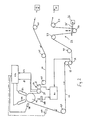
- a length of strip material 10, intended to be printed with graduations and subsequently cut into individual tapes, is provided on a supply roller 12.
- the strip material is drawn off from this supply roller 12 between a pair of feed rollers 14, constituting a drive station, then passes over an idler wheel 16 which is the "impression roller” of a printing station and then between a second pair of feed rollers 18, which are a second drive station.
- the material then passes on and is wound up on a take-up roller 20.
- the take-up roller 20 is preferably driven as is the supply roller 12.
- a conventional accumulator 22 is preferably provided between the supply roller 12 and the first drive station 14 with another accumulator 22 between the second drive station 18 and the take up roller 20.
- the accumulators 22 each have a pair of rollers 23 on fixed axes and a so-called dancing roller 24 in the bight of strip between the rollers 23. This moves up or down as the quantity of strip in this bight between the rollers 23 decreases or increases.
- Each dancing roller 24 is coupled by an arm 25 to a potentiometer 26.
- the potentiometer is connected to a speed control circuit regulating the speed of a conventional a.c. electric motor driving the adjacent roller 12 or 20 through a grear box. This control arrangement operates to keep the dancing roller 24 at a constant height.
- the wheel 16 is mounted on a shaft which is free to rotate.
- a bearing for this shaft is supported by a load cell, indicated diagrammatically at 28, which gives an electrical output signal dependent on the load on the bearing. This serves to indicate the tension in the portion of the strip 10 running between the two drive stations. Measuring tension in this way is a known technique and a suitable load cell and associated circuitry is available from various manufacturers including Bofors Electronics Ltd, Bedford and Nobell Systems Ltd, also in Bedford.
- the lower rollers 15, 19 at each of the drive stations 14, 18 are each driven by a respective servo motor whose speed can be accurately controlled.
- Each carries a shaft encoder. Signals from these encoders and from the load cell 28 are inputs to the electronic control system K1 for these servo motors.
- the shaft encoders could be fitted to the upper, driven rollers at the drive stations.
- This control system K1 drives the servo motors to accelerate the strip from a standing start to the intended operating speed. It then holds the speeds of the motors substantially constant during operation, but also effects slight adjustment of the speed of one or other pair of rollers 14,18 in order to keep the tension in the strip 10 (as detected by load cell 28) constant.
- This system for transporting and tensioning the strip 10 gives reproducible conditions for printing and greatly facilitates setting up a print run as well as facilitating accurate printing.
- a pair of ink jet print heads 32, 34 are positioned so as to be able to direct print onto the strip material 10 as it is passing over the wheel 16.
- the print head 32 is supplied with black ink and is used to print graduations on the tape, together with some of the numerals.
- the print head 34 is supplied with a red ink and is used to print other numerals.
- Each print head delivers minute droplets of ink onto the tape and each droplet forms a small dot.
- the dots are very closely spaced and the positions at which dots are printed is controlled so that the printed dots define graduations (lines) on the tape and numerals. Formation of lines and characters from patterns of dots is of course standard procedure for ink jet and other types of printer. It is preferred to utilise a printer capable of printing simultaneously from each of a row of jets, because this can print a line more readily than by use of a single jet which is deflected.
- a wheel 36 is positioned to bear on the exposed surface of the strip 10 as it runs over the wheel 16, but just before it passes beneath the ink jet print heads 32, 34.
- This wheel 36 is coupled to a shaft encoder and the signals from it are an input (along line Z1) to a second control system K2 used to measure the motion of the strip and control the printers 32, 34.
- the wheel 36 is not used. Instead a shaft encoder is fitted to the upper, driven, roller 37 at the drive station 14. Signals from this encoder are taken to the control system K2 in the same way.
- the shaft encoder is coupled to a wheel or roller which runs on that surface of the strip 10 which receives print and which forms a nip with another wheel or roller.
- Signals from the encoder coupled to the wheel 36 or the roller 37 serve to signal the forward travel of the strip which is in contact with the wheel 16. Once in each revolutlon the encoder coupled to wheel 36 sends a "zero" signal. This is sent separately to the control system K2 along line Z2 and can be used to prevent cumulation of any errors in the signals given during the course of rotation or in counting such signals.
- the control system K2 uses the signals from the shaft encoder (or encoders) as input and computes when the ink jet printers should direct their ink droplets onto the strip to print the required graduations and numerals.
- a photoelectric sensor 38 is positioned to view the strip after printing. It detects the changes in the intensity of reflected light from the tape and thereby is able to detect the transitions from the background of the tape to each of the graduations printed onto it. In this way it is able to detect the leading and trailing edges of each graduation.
- this sensor 38 reads directly from the tape it provides a check on the position of the printed graduations.
- the sensor 38 views a specific point on the path of the moving strip 10. It can observe the instant at which the leading and/or trailing edges of graduations appear at this point.
- the control system K2 which receives signals from the sensor 38 can check that edges appear at the instants predicted by the speed of the strip 10 (as determined from the shaft encoder signals) and the distance from the printing head 32. Alternatively it can check that the intervals between successive edges correspond to the speed of the strip 10.
- control system detects a discrepancy, which signifies an error in printing, it can give an alarm and stop printing if the discrepancy exceeds a permissible tolerance.
- it can correct any discrepancies by making slight variation of the computed instants at which printing occurs, so as to give automatic regulation of the accuracy of printing.
- Checking by means of the sensor 38 may monitor successive graduations on the tape, or may total the observed intervals between graduations over a larger length of tape to obtain a more accurate check.
- a further possibility is to provide a second such sensor 40, as shown in phantom, and check that the instants at which edges of graduations appear corresponds to the distance between the two sensors 38, 40.
- control system K2 When the control system K2 effects automatic regulation of printing by making adjustments in response to signals from the sensor 38 (or sensors 38, 40) it may be possible to dispense with the wheel 36 and its shaft encoder.
- the control system K2 could initially compute the instants for printing on the basis that the strip 10 was travelling at a predetermined speed governed by the system K1 or a speed communicated from the system K1 to the system K2, and subsequently adjust in response to signals from the sensor(s) 38, 40.
- control system K2 With any arrangement of the control system K2, no printing takes place while the drive system 14, 18, K1 is accelerating from a standing start. Instead, when a constant speed is reached, the control system K1 gives a signal to the control system K2 to commence printing.
- the strip is again supplied from a roller 12 via an accumulator 22 as in Figure 1. Neither is included in this Figure.
- the strip is guided around idler rollers 40 to the drive station 14. After printing, it is guided by more idler rollers 40, first to drive station 18 and then via accumulator 22 to a take up roller 20 which is omitted from this Figure.
- the drive stations 14, 18 are oriented so that the strip 10 wraps around a grater arc of the rollers at these drive stations.
- the encoder which provides signals on lines 71, 72 to control system K2 is connected to roller 37 at drive station 14.
- the materials which are employed may be conventional.
- the strip material can be steel strip, phosphated and coated with polyester base paint, as is currently used for tape measures.
- the strip material may be PVC coated fibreglass cloth, as is used at present.
- the ink for the printers can be the same as is currently used for ink jet printing onto cardboard or plastic substrates. Typically it will contain volatile organic solvent, a polymeric resin and a dyestuff.
Landscapes
- Physics & Mathematics (AREA)
- General Physics & Mathematics (AREA)
- Controlling Rewinding, Feeding, Winding, Or Abnormalities Of Webs (AREA)
- Handling Of Sheets (AREA)
- Rotary Presses (AREA)
Applications Claiming Priority (2)
| Application Number | Priority Date | Filing Date | Title |
|---|---|---|---|
| GB898928743A GB8928743D0 (en) | 1989-12-20 | 1989-12-20 | Manufacture of tape measures |
| GB8928743 | 1989-12-20 |
Publications (2)
| Publication Number | Publication Date |
|---|---|
| EP0434422A1 true EP0434422A1 (fr) | 1991-06-26 |
| EP0434422B1 EP0434422B1 (fr) | 1995-04-12 |
Family
ID=10668219
Family Applications (1)
| Application Number | Title | Priority Date | Filing Date |
|---|---|---|---|
| EP90314006A Expired - Lifetime EP0434422B1 (fr) | 1989-12-20 | 1990-12-20 | Fabrication de mètre-rubans |
Country Status (4)
| Country | Link |
|---|---|
| EP (1) | EP0434422B1 (fr) |
| DE (1) | DE69018597T2 (fr) |
| ES (1) | ES2073543T3 (fr) |
| GB (1) | GB8928743D0 (fr) |
Cited By (6)
| Publication number | Priority date | Publication date | Assignee | Title |
|---|---|---|---|---|
| GB2301315A (en) * | 1995-05-23 | 1996-12-04 | Psd Limited | Cable marking apparatus. |
| WO2004106073A1 (fr) | 2003-06-02 | 2004-12-09 | Fisco Tools Limited | Fabrication de rubans de mesure |
| JP2014025852A (ja) * | 2012-07-27 | 2014-02-06 | Hara Doki Kk | 巻尺テープの製造方法 |
| JP2014149163A (ja) * | 2013-01-31 | 2014-08-21 | Sato Holdings Corp | メジャーおよびメジャーの製造方法 |
| CN104822531A (zh) * | 2012-11-30 | 2015-08-05 | Ykk株式会社 | 长条带状体的印刷方法及印刷装置 |
| CN110733237A (zh) * | 2019-11-19 | 2020-01-31 | 珠海市慧虹智能科技有限公司 | 新型全伺服驱动尺带印刷机 |
Families Citing this family (5)
| Publication number | Priority date | Publication date | Assignee | Title |
|---|---|---|---|---|
| DE10008996B4 (de) * | 2000-02-25 | 2008-04-03 | Bayerische Maß-Industrie Arno Keller GmbH | Herstellungsverfahren für Längenmessvorrichtungen in Strang- oder Bandform |
| DE102004029649B8 (de) * | 2004-06-18 | 2006-12-07 | Metzner Maschinenbau Gmbh | Verfahren zum Bedrucken von Drähten |
| DE102011106135B4 (de) * | 2011-06-10 | 2015-01-22 | Theodor Hymmen Verwaltungs Gmbh | Druckvorrichtung zum Bedrucken von plattenförmigen Werkstücken |
| CN113188396B (zh) * | 2021-05-07 | 2022-11-18 | 宁波巨丰工具实业有限公司 | 一种钢卷尺的生产工艺以及钢卷尺 |
| CN116238254B (zh) * | 2022-12-30 | 2025-04-11 | 广东阿诺捷喷墨科技有限公司 | 一种卷尺喷墨印刷机 |
Citations (6)
| Publication number | Priority date | Publication date | Assignee | Title |
|---|---|---|---|---|
| US2471395A (en) * | 1937-08-07 | 1949-05-24 | Keuffel & Esser Co | Method of making measuring tapes |
| US4007866A (en) * | 1975-07-11 | 1977-02-15 | Moore Business Forms, Inc. | Web transport arrangement |
| US4029006A (en) * | 1975-06-26 | 1977-06-14 | The Boeing Company | Method and apparatus for printing indicia on a continuous, elongate, flexible three-dimensional member |
| GB2078208A (en) * | 1980-06-19 | 1982-01-06 | Crosfield Electronics Ltd | Web Feeding Machines |
| EP0160271A2 (fr) * | 1984-04-30 | 1985-11-06 | Volker Dipl.-Ing. Meywald | Procédé et dispositif pour la fabrication de mètre à ruban |
| US4705415A (en) * | 1985-02-11 | 1987-11-10 | Andrei Grombchevsky | Matrix printer and inker for indefinite length articles |
-
1989
- 1989-12-20 GB GB898928743A patent/GB8928743D0/en active Pending
-
1990
- 1990-12-20 DE DE69018597T patent/DE69018597T2/de not_active Expired - Fee Related
- 1990-12-20 ES ES90314006T patent/ES2073543T3/es not_active Expired - Lifetime
- 1990-12-20 EP EP90314006A patent/EP0434422B1/fr not_active Expired - Lifetime
Patent Citations (6)
| Publication number | Priority date | Publication date | Assignee | Title |
|---|---|---|---|---|
| US2471395A (en) * | 1937-08-07 | 1949-05-24 | Keuffel & Esser Co | Method of making measuring tapes |
| US4029006A (en) * | 1975-06-26 | 1977-06-14 | The Boeing Company | Method and apparatus for printing indicia on a continuous, elongate, flexible three-dimensional member |
| US4007866A (en) * | 1975-07-11 | 1977-02-15 | Moore Business Forms, Inc. | Web transport arrangement |
| GB2078208A (en) * | 1980-06-19 | 1982-01-06 | Crosfield Electronics Ltd | Web Feeding Machines |
| EP0160271A2 (fr) * | 1984-04-30 | 1985-11-06 | Volker Dipl.-Ing. Meywald | Procédé et dispositif pour la fabrication de mètre à ruban |
| US4705415A (en) * | 1985-02-11 | 1987-11-10 | Andrei Grombchevsky | Matrix printer and inker for indefinite length articles |
Cited By (11)
| Publication number | Priority date | Publication date | Assignee | Title |
|---|---|---|---|---|
| GB2301315A (en) * | 1995-05-23 | 1996-12-04 | Psd Limited | Cable marking apparatus. |
| GB2301315B (en) * | 1995-05-23 | 1998-05-06 | Psd Limited | Apparatus and method for producing lengths of cable |
| WO2004106073A1 (fr) | 2003-06-02 | 2004-12-09 | Fisco Tools Limited | Fabrication de rubans de mesure |
| CN100584631C (zh) * | 2003-06-02 | 2010-01-27 | 菲斯科工具有限公司 | 卷尺的制造 |
| JP2014025852A (ja) * | 2012-07-27 | 2014-02-06 | Hara Doki Kk | 巻尺テープの製造方法 |
| CN104822531A (zh) * | 2012-11-30 | 2015-08-05 | Ykk株式会社 | 长条带状体的印刷方法及印刷装置 |
| EP2927007A4 (fr) * | 2012-11-30 | 2016-11-02 | Ykk Corp | Procédé d'impression de corps en bande allongée, et dispositif d'impression |
| CN104822531B (zh) * | 2012-11-30 | 2018-01-19 | Ykk株式会社 | 长条带状体的印刷方法及印刷装置 |
| JP2014149163A (ja) * | 2013-01-31 | 2014-08-21 | Sato Holdings Corp | メジャーおよびメジャーの製造方法 |
| CN110733237A (zh) * | 2019-11-19 | 2020-01-31 | 珠海市慧虹智能科技有限公司 | 新型全伺服驱动尺带印刷机 |
| CN110733237B (zh) * | 2019-11-19 | 2021-11-19 | 珠海市慧虹智能科技有限公司 | 新型全伺服驱动尺带印刷机 |
Also Published As
| Publication number | Publication date |
|---|---|
| GB8928743D0 (en) | 1990-02-28 |
| DE69018597D1 (de) | 1995-05-18 |
| ES2073543T3 (es) | 1995-08-16 |
| DE69018597T2 (de) | 1995-12-21 |
| EP0434422B1 (fr) | 1995-04-12 |
Similar Documents
| Publication | Publication Date | Title |
|---|---|---|
| US4848630A (en) | Method and apparatus for positioning a web of material in stepwise transporation thereof | |
| EP1628833B1 (fr) | Fabrication de rubans de mesure | |
| EP0434422B1 (fr) | Fabrication de mètre-rubans | |
| US6053107A (en) | Method and apparatus for registering a pre-printed web on a printing press | |
| US5255598A (en) | Screen printing device with continuous registering of rotating stencils | |
| US5825374A (en) | Apparatus and method for advancing a web | |
| EP2744665B1 (fr) | Imprimante à transfert thermique | |
| EP0729846B1 (fr) | Compensation d'image au moyen de marques de référence imprimées | |
| US5016182A (en) | Register control means for web processing apparatus | |
| EP2730422B1 (fr) | Dispositif d'entraînement de bande et procédé de fonctionnement associé | |
| KR19980042461A (ko) | 연속 멀티컬러 잉크 젯 인쇄기, 상기 인쇄기의 동기화 방법 및,상기 인쇄기를 사용하여 얻어지는 인쇄물 | |
| US4147104A (en) | Key color control system for printing press | |
| GB2448305A (en) | Tension monitoring and control in a tape drive | |
| JPH11508523A (ja) | ゼラチンカプセル包装のためにリボンに印刷をする方法及び装置 | |
| US4296365A (en) | Method and apparatus for correcting errors of feeding of endless belt in automatic screen printing | |
| US20080219742A1 (en) | Tape drive | |
| AU704698B2 (en) | Device for positionally exact printing of continuous sheeting | |
| CN103660623B (zh) | 输送设备和计算输送校正值的方法 | |
| CA2287575C (fr) | Appareil d'impression d'une feuille de metal sans fin non marquee | |
| CN220465056U (zh) | 一种高精度单程打印机 | |
| EP0727315B1 (fr) | Méthode d'impression de lettres pour une machine d'emballage | |
| CN116766796A (zh) | 一种高精度单程打印机 | |
| US20040144272A1 (en) | Multiple-Stand Gravure Printing Machine and Gravure Printing Process | |
| US4334645A (en) | Web indexing apparatus and overprinting machine | |
| JPH11291467A (ja) | 画像形成装置の制御方法、および画像形成装置 |
Legal Events
| Date | Code | Title | Description |
|---|---|---|---|
| PUAI | Public reference made under article 153(3) epc to a published international application that has entered the european phase |
Free format text: ORIGINAL CODE: 0009012 |
|
| AK | Designated contracting states |
Kind code of ref document: A1 Designated state(s): DE ES FR GB IT NL |
|
| 17P | Request for examination filed |
Effective date: 19911218 |
|
| 17Q | First examination report despatched |
Effective date: 19930629 |
|
| GRAA | (expected) grant |
Free format text: ORIGINAL CODE: 0009210 |
|
| AK | Designated contracting states |
Kind code of ref document: B1 Designated state(s): DE ES FR GB IT NL |
|
| REF | Corresponds to: |
Ref document number: 69018597 Country of ref document: DE Date of ref document: 19950518 |
|
| ITF | It: translation for a ep patent filed | ||
| ET | Fr: translation filed | ||
| REG | Reference to a national code |
Ref country code: ES Ref legal event code: FG2A Ref document number: 2073543 Country of ref document: ES Kind code of ref document: T3 |
|
| PLBE | No opposition filed within time limit |
Free format text: ORIGINAL CODE: 0009261 |
|
| STAA | Information on the status of an ep patent application or granted ep patent |
Free format text: STATUS: NO OPPOSITION FILED WITHIN TIME LIMIT |
|
| 26N | No opposition filed | ||
| REG | Reference to a national code |
Ref country code: GB Ref legal event code: IF02 |
|
| PGFP | Annual fee paid to national office [announced via postgrant information from national office to epo] |
Ref country code: FR Payment date: 20051220 Year of fee payment: 16 |
|
| PGFP | Annual fee paid to national office [announced via postgrant information from national office to epo] |
Ref country code: NL Payment date: 20051227 Year of fee payment: 16 |
|
| PGFP | Annual fee paid to national office [announced via postgrant information from national office to epo] |
Ref country code: ES Payment date: 20061004 Year of fee payment: 17 |
|
| PG25 | Lapsed in a contracting state [announced via postgrant information from national office to epo] |
Ref country code: NL Free format text: LAPSE BECAUSE OF NON-PAYMENT OF DUE FEES Effective date: 20070701 |
|
| NLV4 | Nl: lapsed or anulled due to non-payment of the annual fee |
Effective date: 20070701 |
|
| REG | Reference to a national code |
Ref country code: FR Ref legal event code: ST Effective date: 20070831 |
|
| PG25 | Lapsed in a contracting state [announced via postgrant information from national office to epo] |
Ref country code: FR Free format text: LAPSE BECAUSE OF NON-PAYMENT OF DUE FEES Effective date: 20070102 |
|
| REG | Reference to a national code |
Ref country code: ES Ref legal event code: FD2A Effective date: 20071221 |
|
| PG25 | Lapsed in a contracting state [announced via postgrant information from national office to epo] |
Ref country code: ES Free format text: LAPSE BECAUSE OF NON-PAYMENT OF DUE FEES Effective date: 20071221 |
|
| PGFP | Annual fee paid to national office [announced via postgrant information from national office to epo] |
Ref country code: DE Payment date: 20081223 Year of fee payment: 19 |
|
| PGFP | Annual fee paid to national office [announced via postgrant information from national office to epo] |
Ref country code: GB Payment date: 20081219 Year of fee payment: 19 |
|
| PGFP | Annual fee paid to national office [announced via postgrant information from national office to epo] |
Ref country code: IT Payment date: 20081230 Year of fee payment: 19 |
|
| GBPC | Gb: european patent ceased through non-payment of renewal fee |
Effective date: 20091220 |
|
| PG25 | Lapsed in a contracting state [announced via postgrant information from national office to epo] |
Ref country code: DE Free format text: LAPSE BECAUSE OF NON-PAYMENT OF DUE FEES Effective date: 20100701 |
|
| PG25 | Lapsed in a contracting state [announced via postgrant information from national office to epo] |
Ref country code: GB Free format text: LAPSE BECAUSE OF NON-PAYMENT OF DUE FEES Effective date: 20091220 |
|
| PG25 | Lapsed in a contracting state [announced via postgrant information from national office to epo] |
Ref country code: IT Free format text: LAPSE BECAUSE OF NON-PAYMENT OF DUE FEES Effective date: 20091220 |