EP0434640B1 - Dispositif pour commander une boîte de vitesses pour désengagement d'une propulsion à quatres roues motrices pour véhicules - Google Patents
Dispositif pour commander une boîte de vitesses pour désengagement d'une propulsion à quatres roues motrices pour véhicules Download PDFInfo
- Publication number
- EP0434640B1 EP0434640B1 EP90830562A EP90830562A EP0434640B1 EP 0434640 B1 EP0434640 B1 EP 0434640B1 EP 90830562 A EP90830562 A EP 90830562A EP 90830562 A EP90830562 A EP 90830562A EP 0434640 B1 EP0434640 B1 EP 0434640B1
- Authority
- EP
- European Patent Office
- Prior art keywords
- lever
- operating
- engaging
- reduction gear
- rod
- Prior art date
- Legal status (The legal status is an assumption and is not a legal conclusion. Google has not performed a legal analysis and makes no representation as to the accuracy of the status listed.)
- Expired - Lifetime
Links
- 230000005540 biological transmission Effects 0.000 title claims description 25
- 230000007246 mechanism Effects 0.000 description 2
- 230000001681 protective effect Effects 0.000 description 2
Images




Classifications
-
- B—PERFORMING OPERATIONS; TRANSPORTING
- B60—VEHICLES IN GENERAL
- B60K—ARRANGEMENT OR MOUNTING OF PROPULSION UNITS OR OF TRANSMISSIONS IN VEHICLES; ARRANGEMENT OR MOUNTING OF PLURAL DIVERSE PRIME-MOVERS IN VEHICLES; AUXILIARY DRIVES FOR VEHICLES; INSTRUMENTATION OR DASHBOARDS FOR VEHICLES; ARRANGEMENTS IN CONNECTION WITH COOLING, AIR INTAKE, GAS EXHAUST OR FUEL SUPPLY OF PROPULSION UNITS IN VEHICLES
- B60K20/00—Arrangement or mounting of change-speed gearing control devices in vehicles
- B60K20/02—Arrangement or mounting of change-speed gearing control devices in vehicles of initiating means
- B60K20/04—Arrangement or mounting of change-speed gearing control devices in vehicles of initiating means floor mounted
-
- B—PERFORMING OPERATIONS; TRANSPORTING
- B60—VEHICLES IN GENERAL
- B60K—ARRANGEMENT OR MOUNTING OF PROPULSION UNITS OR OF TRANSMISSIONS IN VEHICLES; ARRANGEMENT OR MOUNTING OF PLURAL DIVERSE PRIME-MOVERS IN VEHICLES; AUXILIARY DRIVES FOR VEHICLES; INSTRUMENTATION OR DASHBOARDS FOR VEHICLES; ARRANGEMENTS IN CONNECTION WITH COOLING, AIR INTAKE, GAS EXHAUST OR FUEL SUPPLY OF PROPULSION UNITS IN VEHICLES
- B60K23/00—Arrangement or mounting of control devices for vehicle transmissions, or parts thereof, not otherwise provided for
- B60K23/08—Arrangement or mounting of control devices for vehicle transmissions, or parts thereof, not otherwise provided for for changing number of driven wheels, for switching from driving one axle to driving two or more axles
-
- F—MECHANICAL ENGINEERING; LIGHTING; HEATING; WEAPONS; BLASTING
- F16—ENGINEERING ELEMENTS AND UNITS; GENERAL MEASURES FOR PRODUCING AND MAINTAINING EFFECTIVE FUNCTIONING OF MACHINES OR INSTALLATIONS; THERMAL INSULATION IN GENERAL
- F16H—GEARING
- F16H59/00—Control inputs to control units of change-speed- or reversing-gearings for conveying rotary motion
- F16H59/02—Selector apparatus
-
- F—MECHANICAL ENGINEERING; LIGHTING; HEATING; WEAPONS; BLASTING
- F16—ENGINEERING ELEMENTS AND UNITS; GENERAL MEASURES FOR PRODUCING AND MAINTAINING EFFECTIVE FUNCTIONING OF MACHINES OR INSTALLATIONS; THERMAL INSULATION IN GENERAL
- F16H—GEARING
- F16H61/00—Control functions within control units of change-speed- or reversing-gearings for conveying rotary motion ; Control of exclusively fluid gearing, friction gearing, gearings with endless flexible members or other particular types of gearing
- F16H61/26—Generation or transmission of movements for final actuating mechanisms
- F16H61/36—Generation or transmission of movements for final actuating mechanisms with at least one movement being transmitted by a cable
Definitions
- the present invention relates in general to a disengageable four-wheel-drive transmission for a motor car of the type including a gearbox, permanent drive means for one pair of wheels, engageable and disengageable drive means for the other pair of wheels, means for engaging and disengaging the engageable and disengageable drive means, a reduction gear, means for engaging and disengaging the reduction gear, at least one lockable differential, and means for locking and unlocking the differential.
- the invention concerns a unit for operating such a transmission, including a gear lever and means for operating the means for engaging and disengaging the drive means, the reduction-gear engagement and disengagement means, and the means for locking and unlocking the differential.
- the object of the present invention is to provide an operating unit of the type defined above which is compact and functional and which makes the operations it controls quicker and easier, whilst ensuring that they are carried out in the correct predetermined sequence without the risk of errors.
- an operating unit of the type specified characterised in that the operating means comprise a single lever translatable axially between a lowered position and a raised position to disengage and engage the drive means respectively, the lever being rotatable about its axis of translation, when it is in the raised position, between two angular positions in which the reduction gear is engaged and disengaged respectively, and a rod mounted within the lever and movable axially relative thereto by means of a projecting operating end to lock and unlock the differential when the lever is in the raised position and in the angular position in which the reduction gear is engaged.
- the invention conveniently provides, associated with the lever, a first locking device for preventing the lever from rotating to engage or disengage the reduction gear when it is in its lowered position in which the drive means are disengaged, and a second locking device for preventing the rod from moving axially when the lever is in the angular position in which the reduction gear is disengaged.
- the invention also provides particularly compact and easily implemented kinematic mechanisms for the selection and engagement of the gear ratios by means of the gear lever and for the engagement and disengagement of the drive means and the reduction gear.
- these kinematic mechanisms are housed in a common protective housing which acts as a support for the two levers.
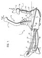
- an operating unit for application to a motor car with a generally conventional four-wheel-drive transmission is generally indicated 1.
- a transmission includes a gearbox, whose input is shown schematically at 2 in Figure 1, associated with a permanent drive unit for the front wheels of the car and a rear-wheel drive unit which can be connected to the front-wheel drive unit by means of an engageable and disengageable clutch whose input is shown schematically at 3 in Figure 1.
- the transmission also includes, again in known manner, an engageable and disengageable reduction gear whose input is shown schematically at 4 in Figure 1, a front differential, and a rear differential with a known locking and unlocking device which is normally electro-pneumatic.
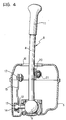
- the control unit 1 includes essentially a protective support housing 5 from the top of which project a front lever 6 for operating the gearbox 2 and a single rear lever 7 operable in a predetermined sequence to engage and disengage the rear-wheel drive and the reduction gear and to lock and unlock the rear differential.
- the front lever 6 includes a rod 8 supported at its lower end by the housing 5 by means of a ball joint 9 and movable with clearance in a hole 10 in the top of the housing 5.
- the rod 8 has a hand-grip 11 at its upper end.
- a radial side arm 12 is fixed to the ball joint 9 and in turn has a spherical head 13 engaged in a seat 14 at the lower end of a right-angled element 15 which pivots about a transverse pin 16 carried by the housing 5.
- the upper end of the pivoting element 15 is articulated at 17 to one end 18 of a Bowden cable transmission 19.
- the rod 8 of the lever 6 has a lateral appendage 20 to which one end 22 of a second Bowden cable transmission 23 is articulated at 21.
- the transmissions 23 and 19 pass through the housing 5 in correspondnece with respective fixing bushes 24 and 25 and are connected to the gearbox 2 for selecting the gears (as a result of the transverse movements of the lever 6) and engaging them (as a result of the longitudinal movements of the lever 6) respectively.
- the rear lever 7 is constituted by a cylindrical rod 7a, whose axis is indicated A, slidable axially and rotatable in a tubular guide element 26 fixed by a flange 27 to the top of the housing 5.
- the rod 7a carries a shaped hand-grip 28 at its upper end and its lower end has a splined part 29 which extends within the housing 5.
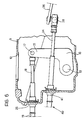
- the splined part 29 passes through an externally-threaded bush 30 screwed to the base of the tubular guide 26 and a sleeve 31 supported rotatably below the bush 30 by a bracket 32.
- the sleeve 31 is internally splined and is coupled for rotation with the splined part 29.
- a bent arm 33 is fixed to the sleeve 31 and its free end carries a pin 34 substantially parallel to the axis A of the lever 7 and engaged in a slot 35 in one end of a U-shaped transmission element 36 whose opposite end is articulated to the housing 5 by means of a pivot pin 37 parallel to the pin 34.
- the transmission element 36 Near the pin 37, the transmission element 36 carries a ball joint 38 to which one end 39 of a Bowden cable transmission 40 is connected.
- the transmission 40 is anchored to the front wall of the housing 5 by means of a bush 41 and controls the engagement and disengagement of the reduction gear 4.
- a grooved bush 29a is fixed to the lower end of the splined portion 29 and an end 43 of a rocker element 44 pivotable on the housing 5 about a transverse pin 45 is engaged pivotably therein.
- the other end of the rocker element 44 is articulated at 46 to an end 47 of a Bowden cable transmission 48 which is also anchored to the front wall of the housing 5 by means of a bush 49.
- the transmission 48 controls the engagement and disengagement of the rear-wheel drive of the car.
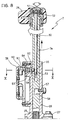
- the upper portion of the rod 7a that is, the portion guided in the tubular element 26, is hollow and houses coaxially a slidable rod 50 whose upper end has an operating push-button 51 which projects from the hand-grip 28 under the action of a thrust spring 52.
- the lower end of the rod 50 has a tapered, wedge-shaped portion 53 which cooperates in the manner explained below with a ball 54 housed in a radial recess 55 in the rod 7a.
- the rod 7a has an external axial groove 56 which is engaged by a radial pin 57 carried by the tubular element 26 and, at its lower end, has an angularly-widened part 58 extending from only one side of the groove 56.
- a box 59 is fitted to the tubular guide 26 on the side opposite the pin 57 and contains an electrical switch 60 connected to the electro-pneumatic device for locking and unlocking the rear differential of the car.
- the switch 60 has a pivotable operating member 61 operated by a push rod 62 slidable in a radial hole 63 in the tubular guide 26.
- the push rod 62 is normally urged against the rod 7a by a spring 64.
- the lever 7 operates as follows.
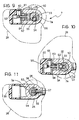
- the rod 7a can be moved axially between the lowered position shown in Figure 7 and the raised position shown in Figure 8 by means of the hand-grip 28.
- the rod 7a can also be rotated through approximately 90° between the angular position shown in Figures 9 and 11 and that shown in Figure 10, but only when it is in the raised position of Figure 8.
- the rod 50 can be moved axially downwardly from the position shown in Figure 7 to that shown in Figure 8 only when the rod 7a is in the angular position shown in Figure 10.
- the ball 54 is radially in correspondence with the hole 63, enabling the rod 50 to be moved downwardly by the manual operation of the push-button 51 against the action of the spring 52.
- the wedge-shaped end 53 of the rod 50 moves the ball 54 radially in the hole 63, resulting in a radial movement of the rod 62 which moves the actuator 61 and switches the switch 60.
- the switching locks the rear, differential which can subsequently be unlocked by a further lowering of the rod 50 to return the switch 60 to its original condition.
- the rod 7a In order to disengage the reduction gear and the rear-wheel drive, the rod 7a must be rotated from the angular position of Figure 10 to that of Figure 9 and translated from the raised position of Figure 8 to the lowered position of Figure 7, the sequence being the reverse of that described above.
- the gearbox is operated in conventional manner by the operation of the gear lever 6 transversely to select the gear ratios (by means of the cable transmission 23) and longitudinally to engage the ratios selected (by means of the cable transmission 19).
- control unit enables all the kinematic operating components to be assembled in a compact unit which is well protected from the outside.
- the unit also ensures very easy and convenient operation and affords a univocal operating sequence without risks of incorrect operation.
Landscapes
- Engineering & Computer Science (AREA)
- Mechanical Engineering (AREA)
- General Engineering & Computer Science (AREA)
- Chemical & Material Sciences (AREA)
- Combustion & Propulsion (AREA)
- Transportation (AREA)
- Arrangement And Mounting Of Devices That Control Transmission Of Motive Force (AREA)
- Control Of Transmission Device (AREA)
- Retarders (AREA)
Claims (8)
- Transmission à quatre roues motrices débrayable pour un véhicule automobile comprenant une botte de vitesses, des moyens d'entraînement permanent pour une première paire de roues, des moyens d'entraînement embrayables et débrayables pour l'autre paire de roues, des moyens pour embrayer et débrayer les moyens d'entraînement embrayables et débrayables, un réducteur, des moyens pour embrayer et débrayer le réducteur, au moins un différentiel blocable, des moyens pour bloquer et débloquer le différentiel, un levier de vitesses, et des moyens servant à actionner les moyens pour embrayer et débrayer les moyens d'entrainement, les moyens d'embrayage et de débrayage du réducteur et les moyens pour bloquer et débloquer le différentiel, caractérisée en ce que les moyens de commande comprennent un unique levier (7) qu'on peut déplacer en translation axiale entre une position abaissée et une position relevée pour débrayer et embrayer respectivement les moyens d'entraînement (3), le levier (7) pouvant tourner autour de son axe de translation (A), lorsqu'il est dans la position relevée, entre deux positions angulaires dans lesquelles le réducteur (4) est embrayé et débrayé respectivement, et une tige (50) montée à l'intérieur du levier (7) et pouvant être déplacée axialement par rapport à celui-ci, à l'aide d'une extrémité de commande saillante (51), pour bloquer et débloquer le différentiel lorsque le levier (7) est dans la position relevée dans laquelle les moyens d'entraînement (3) sont embrayés et dans la position angulaire dans laquelle le réducteur (4) est embrayé.
- Unité de commande selon la revendication 1, caractérisée en ce que le levier (7) est associé à un premier dispositif de verrouillage (56, 57) pour empêcher le levier (7) de tourner pour embrayer ou débrayer le réducteur (4) lorsqu'il est dans la position abaissée dans lequelle les moyens d'entraînement (3) sont débrayés, et un second dispositif de verrouillage (54) pour empêcher la tige (50) de se déplacer axialement lorsque le levier (7) est dans la position angulaire dans laquelle le réducteur (4) est débrayé.
- Unité de commande selon la revendication 2, caractérisée en ce que les moyens servant à bloquer et débloquer le différentiel comprennent un interrupteur électrique (60) qui est fixe par rapport au levier (7), et un élément de commande (62) qui peut se déplacer transversalement à l'axe de translation (A) du levier (7) pour actionner l'interrupteur (60), et en ce que le levier (7) présente un trou transversal (55) dans lequel peut se déplacer une bille (54) contre laquelle porte une partie de poussée (53) de la tige (50) à section décroissante, en forme de coin, le trou (55) étant adapté pour être positionné dans l'alignement axial et angulaire de l'élément de commande mobile (62), de manière que l'élément de commande (62) puisse être mis en mouvement pour actionner l'interrupteur électrique (60) à l'aide de la partie de poussée (53) en forme de coin de la tige (50) lorsque le levier (7) se trouve dans la position relevée, dans laquelle les moyens d'entraînement (3) sont embraqués, et dans la position angulaire dans laquelle le réducteur (4) est embrayé,
- Unité de commande selon la revendication 3, caractérisé en ce que le premier dispositif de verrouillage comprend une cheville de retenue transversale (57) qui est fixe par rapport au levier (7) et est engagée dans une rainure axiale (56) de ce levier, la rainure ayant une partie (58) qui est prolongée en angle dans un seul sens et est adaptée pour être positionnée au niveau axial de la cheville (57) lorsque le levier (7) se trouve dans sa position relevée.
- Unité de commande selon une quelconque des revendications précédentes, caractérisée en ce que les moyens servant à embrayer et débrayer les moyens d'entraînement (3) comprennent un élément de renvoi (44) qu'on peut faire pivoter autour d'un axe (45) transversal à l'axe de translation (A) du levier (7) et qui est commandé à une première extrémité (43) par le levier (7) tandis qu'à l'autre extrémité (42), il est relié à une transmission (48) à câble Bowden.
- Unité de commande selon une quelconque des revendications précédentes, caractérisé en ce que les moyens servant à embrayer et débrayer le réducteur (4) comprennent un premier bras (33) rendu solidaire en rotation du levier (7) et un second bras (36) ayant une extrémité qui peut tourner autour d'un axe (37) sensiblement parallèle à l'axe de translation (A) du levier (7), tandis que son extrémité opposée (35) est actionnée par le premier bras (33), le second bras (36) étant relié à une transmission (30) à câble Bowden.
- Unité de commande selon une quelconque des revendications précédentes, caractérisé en ce que des moyens (20) servant à sélectionner les rapports d'engrenage et des moyens (12, 15) servant à engager les rapports d'engrenage sont fonctionnellement associés au levier (6) pour commander la boîte de vitesses (2) et sont reliés aux transmissions à câble Bowden respectives (23, 19).
- Unité de commande selon une quelconque des revendications 5 à 7, caractérisée en ce que le levier (7) et le levier (6) servant à commander la boîte de vitesses (2) sont supportés par un carter commun (5) qui contient les moyens servant à embrayer et débrayer les moyens d'entraînement (3), les moyens servant à embrayer et débrayer le réducteur (4), et les moyens servant à sélectionner et engager les rapports d'engrenage de la boîte de vitesses (2), et auquel les transmissions à câble Bowden (19, 23, 40, 48) sont reliées.
Applications Claiming Priority (2)
| Application Number | Priority Date | Filing Date | Title |
|---|---|---|---|
| IT6815989 | 1989-12-22 | ||
| IT06815989A IT1238422B (it) | 1989-12-22 | 1989-12-22 | Gruppo di comando di una trasmissione a trazione integrale disinseribile per autovetture. |
Publications (2)
| Publication Number | Publication Date |
|---|---|
| EP0434640A1 EP0434640A1 (fr) | 1991-06-26 |
| EP0434640B1 true EP0434640B1 (fr) | 1993-03-17 |
Family
ID=11308244
Family Applications (1)
| Application Number | Title | Priority Date | Filing Date |
|---|---|---|---|
| EP90830562A Expired - Lifetime EP0434640B1 (fr) | 1989-12-22 | 1990-12-04 | Dispositif pour commander une boîte de vitesses pour désengagement d'une propulsion à quatres roues motrices pour véhicules |
Country Status (5)
| Country | Link |
|---|---|
| EP (1) | EP0434640B1 (fr) |
| DE (1) | DE69001123T2 (fr) |
| ES (1) | ES2039125T3 (fr) |
| IT (1) | IT1238422B (fr) |
| RU (1) | RU2010733C1 (fr) |
Families Citing this family (6)
| Publication number | Priority date | Publication date | Assignee | Title |
|---|---|---|---|---|
| GB2345097B (en) * | 1998-12-23 | 2003-02-12 | Aggo Ltd | Differential lock and four wheel drive control arrangement |
| RU2196057C2 (ru) * | 2000-09-11 | 2003-01-10 | Открытое акционерное общество "ГАЗ" | Механизм управления раздаточной коробкой транспортного средства |
| FR2958591B1 (fr) * | 2010-04-12 | 2012-06-01 | Renault Sa | Procede de fonctionnement d'un systeme de transmission d'un vehicule automobile |
| FR2976994B1 (fr) * | 2011-06-23 | 2013-06-14 | Renault Sa | Dispositif d'actionnement d'une boite de vitesses avec masse d'inertie clipsee |
| RU177709U1 (ru) * | 2017-08-08 | 2018-03-06 | Публичное акционерное общество "КАМАЗ" | Мастер-опора тросового привода управления механизмом |
| WO2025136146A1 (fr) * | 2023-12-18 | 2025-06-26 | Общество С Ограниченной Ответственностью "Вездеходы "Бурлак" | Mécanisme de commutation des modes d'une boîte de transfert |
Family Cites Families (5)
| Publication number | Priority date | Publication date | Assignee | Title |
|---|---|---|---|---|
| FR2077082A5 (fr) * | 1970-01-29 | 1971-10-15 | Daimler Benz Ag | |
| US3795152A (en) * | 1972-08-17 | 1974-03-05 | Caterpillar Tractor Co | Dual lever control |
| US4077276A (en) * | 1976-10-21 | 1978-03-07 | Knox Jr William G | Actuator lever lock for a four wheel drive vehicle transfer case |
| US4221277A (en) * | 1978-09-27 | 1980-09-09 | Antonio Mastropieri | Device for automatically returning a transmission control to neutral |
| CS212111B1 (en) * | 1980-08-18 | 1982-02-26 | Milan Havranek | Gearing mechanism for,under load, eligible gear changing of the front drive of vehicles with propulsion of all four wheels |
-
1989
- 1989-12-22 IT IT06815989A patent/IT1238422B/it active IP Right Grant
-
1990
- 1990-12-04 EP EP90830562A patent/EP0434640B1/fr not_active Expired - Lifetime
- 1990-12-04 ES ES199090830562T patent/ES2039125T3/es not_active Expired - Lifetime
- 1990-12-04 DE DE9090830562T patent/DE69001123T2/de not_active Expired - Fee Related
- 1990-12-21 RU SU904831802A patent/RU2010733C1/ru active
Also Published As
| Publication number | Publication date |
|---|---|
| IT1238422B (it) | 1993-07-26 |
| RU2010733C1 (ru) | 1994-04-15 |
| EP0434640A1 (fr) | 1991-06-26 |
| DE69001123T2 (de) | 1993-06-24 |
| ES2039125T3 (es) | 1993-08-16 |
| DE69001123D1 (de) | 1993-04-22 |
| IT8968159A0 (it) | 1989-12-22 |
| IT8968159A1 (it) | 1991-06-22 |
Similar Documents
| Publication | Publication Date | Title |
|---|---|---|
| US4821605A (en) | Transmission shift control assembly | |
| US5615564A (en) | Door locking device with an antitheft mechanism | |
| EP0692595B1 (fr) | Système de serrure pour voiture | |
| US5704251A (en) | Motor vehicle gearbox with internal shift system | |
| US4938042A (en) | Shift lever locking apparatus | |
| WO1995012773A1 (fr) | Selecteur pour transmission de vehicule | |
| US4759203A (en) | Steering and ignition lock for a motor vehicle | |
| US4959982A (en) | Interlock device between an ignition lock and a manual selector lever for an automatic gear-change transmission | |
| EP0434640A1 (fr) | Dispositif pour commander une boîte de vitesses pour désengagement d'une propulsion à quatres roues motrices pour véhicules | |
| US6082213A (en) | Control device for the transmission of a vehicle | |
| US5492031A (en) | Steering column transmission shifting assembly | |
| US5961166A (en) | Automotive vehicle door handle assembly | |
| US5022504A (en) | Column shift with safety device | |
| US6598494B1 (en) | Selector device for a vehicle with an automatic gear system | |
| EP0149020A2 (fr) | Dispositifs pour le changement de vitesse et pour la commande d'une transmission en particulier pour véhicules industriels | |
| EP0037166B1 (fr) | Mécanisme de rappel pour levier de commande de la transmission et dispositif de verrouillage de colonne | |
| US5025678A (en) | Column shift lever device | |
| EP1146256B1 (fr) | Dispositif de commande de changement de vitesse pour tracteurs | |
| US6345521B1 (en) | Shift lock mechanism for shift lever | |
| JPH045406Y2 (fr) | ||
| GB2345097A (en) | Selector lever for a differential lock and four wheel drive actuation | |
| JPH031653Y2 (fr) | ||
| EP1081415B1 (fr) | Commande du changement de vitesse pour un véhicule automobile | |
| JPH06286493A (ja) | 自動変速機の変速操作装置 | |
| JPH0443382Y2 (fr) |
Legal Events
| Date | Code | Title | Description |
|---|---|---|---|
| PUAI | Public reference made under article 153(3) epc to a published international application that has entered the european phase |
Free format text: ORIGINAL CODE: 0009012 |
|
| AK | Designated contracting states |
Kind code of ref document: A1 Designated state(s): DE ES FR GB SE |
|
| 17P | Request for examination filed |
Effective date: 19910724 |
|
| 17Q | First examination report despatched |
Effective date: 19920626 |
|
| GRAA | (expected) grant |
Free format text: ORIGINAL CODE: 0009210 |
|
| AK | Designated contracting states |
Kind code of ref document: B1 Designated state(s): DE ES FR GB SE |
|
| REF | Corresponds to: |
Ref document number: 69001123 Country of ref document: DE Date of ref document: 19930422 |
|
| ET | Fr: translation filed | ||
| REG | Reference to a national code |
Ref country code: ES Ref legal event code: FG2A Ref document number: 2039125 Country of ref document: ES Kind code of ref document: T3 |
|
| PGFP | Annual fee paid to national office [announced via postgrant information from national office to epo] |
Ref country code: SE Payment date: 19931117 Year of fee payment: 4 |
|
| PGFP | Annual fee paid to national office [announced via postgrant information from national office to epo] |
Ref country code: ES Payment date: 19931203 Year of fee payment: 4 |
|
| PLBE | No opposition filed within time limit |
Free format text: ORIGINAL CODE: 0009261 |
|
| STAA | Information on the status of an ep patent application or granted ep patent |
Free format text: STATUS: NO OPPOSITION FILED WITHIN TIME LIMIT |
|
| 26N | No opposition filed | ||
| PG25 | Lapsed in a contracting state [announced via postgrant information from national office to epo] |
Ref country code: GB Effective date: 19941204 |
|
| PG25 | Lapsed in a contracting state [announced via postgrant information from national office to epo] |
Ref country code: SE Effective date: 19941205 Ref country code: ES Free format text: LAPSE BECAUSE OF THE APPLICANT RENOUNCES Effective date: 19941205 |
|
| EAL | Se: european patent in force in sweden |
Ref document number: 90830562.6 |
|
| GBPC | Gb: european patent ceased through non-payment of renewal fee |
Effective date: 19941204 |
|
| EUG | Se: european patent has lapsed |
Ref document number: 90830562.6 |
|
| PGFP | Annual fee paid to national office [announced via postgrant information from national office to epo] |
Ref country code: DE Payment date: 19971124 Year of fee payment: 8 |
|
| PGFP | Annual fee paid to national office [announced via postgrant information from national office to epo] |
Ref country code: FR Payment date: 19981230 Year of fee payment: 9 |
|
| PG25 | Lapsed in a contracting state [announced via postgrant information from national office to epo] |
Ref country code: DE Free format text: LAPSE BECAUSE OF NON-PAYMENT OF DUE FEES Effective date: 19991001 |
|
| PG25 | Lapsed in a contracting state [announced via postgrant information from national office to epo] |
Ref country code: FR Free format text: LAPSE BECAUSE OF NON-PAYMENT OF DUE FEES Effective date: 20000831 |
|
| REG | Reference to a national code |
Ref country code: FR Ref legal event code: ST |
|
| REG | Reference to a national code |
Ref country code: ES Ref legal event code: FD2A Effective date: 20010402 |