EP0434648A2 - Tunnelbohrmaschine - Google Patents
Tunnelbohrmaschine Download PDFInfo
- Publication number
- EP0434648A2 EP0434648A2 EP90850359A EP90850359A EP0434648A2 EP 0434648 A2 EP0434648 A2 EP 0434648A2 EP 90850359 A EP90850359 A EP 90850359A EP 90850359 A EP90850359 A EP 90850359A EP 0434648 A2 EP0434648 A2 EP 0434648A2
- Authority
- EP
- European Patent Office
- Prior art keywords
- tunnel
- machine housing
- boring
- machine
- boring head
- Prior art date
- Legal status (The legal status is an assumption and is not a legal conclusion. Google has not performed a legal analysis and makes no representation as to the accuracy of the status listed.)
- Granted
Links
Images

Classifications
-
- E—FIXED CONSTRUCTIONS
- E21—EARTH OR ROCK DRILLING; MINING
- E21D—SHAFTS; TUNNELS; GALLERIES; LARGE UNDERGROUND CHAMBERS
- E21D9/00—Tunnels or galleries, with or without linings; Methods or apparatus for making thereof; Layout of tunnels or galleries
- E21D9/10—Making by using boring or cutting machines
- E21D9/11—Making by using boring or cutting machines with a rotary drilling-head cutting simultaneously the whole cross-section, i.e. full-face machines
Definitions
- the present invention relates to a tunnel boring machine for reaming a pilot tunnel.
- the present invention which is defined in the subsequent claims, aims at solving the above mentioned problem through preventing blocks broken loose from getting stuck between the boring head and the tunnel front.
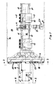
- fig 1 shows a tunnel boring machine according to the invention from the side partly in section.
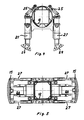
- Fig 2 shows a view according to 2-2 in fig 1.
- Fig 3 shows a view according to 3-3 in fig 1.
- Fig 4 shows a view according to 4-4 in fig 1 partly in section.
- Fig 5 shows a section according to 5-5 in fig 1.
- the tunnel boring machine for reaming the pilot tunnel 11 shown in the drawings comprises a machine housing 12.
- the machine housing is built up from a number of modules through which the machine in a relatively simple way can be rebuilt to be adapted to different requirements in different tunnels.
- the shown tunnel boring machine is provided with two units provided with clamping shoes 15 for clamping the machine in the tunnel 14.
- the clamping shoes act against the tunnel wall 16.
- the clamping shoes are movable relative to machine housing 12 in the longitudinal direction of the tunnel by means of hydraulic cylinders If.
- a boring head 13 is rotateably mounted on machine housing 12.
- the boring head is rotated relative to the machine housing by one or more, not shown, electric motors. Boring head 13 is pressed against tunnel front 15 by means of hydraulic cylinders If.
- a unit provided with support legs 21 is mounted between the units with clamping shoes 15. By means of these support legs, comprising hydraulic cylinders, the tunnel boring machine is aligned vertically.
- the different machine housing parts and the boring head are provided with flanges having standard form so that the different modules can be exchanged without extensive design work.
- Machine housing 12 is at its front end provided with a projecting part which extends into the pilot tunnel 11.
- This projecting part comprises a part 20 being fixed relative to the machine housing and a shield 19.
- Shield 19 is by means of wires or chains 22 connected with fixed part 20. As a result shield 19 is moved into pilot tunnel 11 when tunnel 14 is bored.
- the purpose of shield 19 is to prevent that blocks broken loose at the transition between tunnel 14 and pilot tunnel 11 fall down and get stuck between boring head 13 and tunnel front 18.
- Boring head 13 is provided with a number of cutters 23 for crushing of the rock. These cutters are worn and must be exchanged at intervals.
- shield 19 can be separated from the fixed part 20. After separation boring head 13 can be moved backwards to give access to the cutters. Shield 19 then remains as protection at the transition between tunnel 14 and pilot tunnel 11.
- support legs 21 are provided with feet 24.
- Hydraulic cylinders 25 are connected between support legs 21 and machine housing 12. Cylinders 25 make it possible to turn machine housing 12 about the longitudinal axis of the tunnel when clamping shoes 15 are not in engagement with tunnel wall 16. Through this it is possible to counteract the turning which the tunnel boring machine often encounters as a result of reaction forces during the boring.
- Horizontal control of the tunnel boring machine is obtained by means of hydraulic cylinders 27 which move the machine housing 12 relative to clamping shoes 15. When the adjustment has been done clamping is obtained by pressurization of pistons 26.
Landscapes
- Engineering & Computer Science (AREA)
- Mining & Mineral Resources (AREA)
- Environmental & Geological Engineering (AREA)
- Life Sciences & Earth Sciences (AREA)
- General Life Sciences & Earth Sciences (AREA)
- Geochemistry & Mineralogy (AREA)
- Geology (AREA)
- Excavating Of Shafts Or Tunnels (AREA)
- Earth Drilling (AREA)
- Protection Of Plants (AREA)
Applications Claiming Priority (2)
| Application Number | Priority Date | Filing Date | Title |
|---|---|---|---|
| SE8903919 | 1989-11-22 | ||
| SE8903919A SE464772B (sv) | 1989-11-22 | 1989-11-22 | Tunnelborrningsmaskin |
Publications (3)
| Publication Number | Publication Date |
|---|---|
| EP0434648A2 true EP0434648A2 (de) | 1991-06-26 |
| EP0434648A3 EP0434648A3 (en) | 1992-07-29 |
| EP0434648B1 EP0434648B1 (de) | 1995-06-28 |
Family
ID=20377549
Family Applications (1)
| Application Number | Title | Priority Date | Filing Date |
|---|---|---|---|
| EP90850359A Expired - Lifetime EP0434648B1 (de) | 1989-11-22 | 1990-10-26 | Tunnelbohrmaschine |
Country Status (9)
| Country | Link |
|---|---|
| US (1) | US5104261A (de) |
| EP (1) | EP0434648B1 (de) |
| JP (1) | JPH03290595A (de) |
| AT (1) | ATE124497T1 (de) |
| AU (1) | AU632385B2 (de) |
| CA (1) | CA2030180A1 (de) |
| DE (1) | DE69020524T2 (de) |
| SE (1) | SE464772B (de) |
| ZA (1) | ZA909361B (de) |
Cited By (1)
| Publication number | Priority date | Publication date | Assignee | Title |
|---|---|---|---|---|
| CN104806259A (zh) * | 2015-05-27 | 2015-07-29 | 上海绿地建设(集团)有限公司 | 盾构始发阶段刀盘在冻土中快速脱困的施工方法 |
Families Citing this family (4)
| Publication number | Priority date | Publication date | Assignee | Title |
|---|---|---|---|---|
| JP2578226Y2 (ja) * | 1993-02-19 | 1998-08-06 | 株式会社小松製作所 | シールド掘進機の予備カッタ装置 |
| JP3483225B2 (ja) * | 1995-03-22 | 2004-01-06 | 株式会社小松製作所 | トンネル掘削機 |
| US9039330B1 (en) * | 2010-06-01 | 2015-05-26 | LLAJ, Inc. | Pipe boring shield |
| DE102014105014A1 (de) * | 2014-04-08 | 2015-10-08 | Montanuniversität Leoben | Hochpräzise Sensorik zum Ermitteln einer mechanischen Belastung eines Abbauwerkzeugs einer Tunnelbohrmaschine |
Family Cites Families (5)
| Publication number | Priority date | Publication date | Assignee | Title |
|---|---|---|---|---|
| DE1188021B (de) * | 1959-07-07 | 1965-03-04 | Bade & Co Gmbh | Verfahren und Vorrichtung zum Vortreiben von Tunnels oder Strecken im Bergbau |
| GB2133439B (en) * | 1982-12-03 | 1986-03-12 | Mitsui Constr | Method of enlarging a tunnel |
| JPS59192193A (ja) * | 1983-04-14 | 1984-10-31 | 株式会社イセキ開発工機 | シールド掘進装置 |
| JPS63125799A (ja) * | 1986-11-13 | 1988-05-28 | 川崎重工業株式会社 | シ−ルド式トンネル掘削機 |
| JPH086557B2 (ja) * | 1989-12-05 | 1996-01-24 | 株式会社イセキ開発工機 | シールド型トンネル掘削機 |
-
1989
- 1989-11-22 SE SE8903919A patent/SE464772B/sv not_active IP Right Cessation
-
1990
- 1990-10-26 DE DE69020524T patent/DE69020524T2/de not_active Expired - Fee Related
- 1990-10-26 AT AT90850359T patent/ATE124497T1/de active
- 1990-10-26 EP EP90850359A patent/EP0434648B1/de not_active Expired - Lifetime
- 1990-11-16 JP JP2308987A patent/JPH03290595A/ja active Pending
- 1990-11-16 CA CA002030180A patent/CA2030180A1/en not_active Abandoned
- 1990-11-19 US US07/615,467 patent/US5104261A/en not_active Expired - Fee Related
- 1990-11-21 AU AU66783/90A patent/AU632385B2/en not_active Ceased
- 1990-11-22 ZA ZA909361A patent/ZA909361B/xx unknown
Cited By (2)
| Publication number | Priority date | Publication date | Assignee | Title |
|---|---|---|---|---|
| CN104806259A (zh) * | 2015-05-27 | 2015-07-29 | 上海绿地建设(集团)有限公司 | 盾构始发阶段刀盘在冻土中快速脱困的施工方法 |
| CN104806259B (zh) * | 2015-05-27 | 2017-03-01 | 上海绿地建设(集团)有限公司 | 盾构始发阶段刀盘在冻土中快速脱困的施工方法 |
Also Published As
| Publication number | Publication date |
|---|---|
| US5104261A (en) | 1992-04-14 |
| ATE124497T1 (de) | 1995-07-15 |
| DE69020524D1 (de) | 1995-08-03 |
| ZA909361B (en) | 1992-01-29 |
| AU632385B2 (en) | 1992-12-24 |
| AU6678390A (en) | 1991-05-30 |
| EP0434648A3 (en) | 1992-07-29 |
| CA2030180A1 (en) | 1991-05-23 |
| DE69020524T2 (de) | 1995-11-30 |
| JPH03290595A (ja) | 1991-12-20 |
| EP0434648B1 (de) | 1995-06-28 |
| SE8903919D0 (sv) | 1989-11-22 |
| SE464772B (sv) | 1991-06-10 |
Similar Documents
| Publication | Publication Date | Title |
|---|---|---|
| DE2930136C2 (de) | Streckenvortriebsmaschine für den Untertagebau | |
| CA2015719A1 (en) | Continuously operating open-cast mining device with a cylindrical breaking tool | |
| EP0434648A2 (de) | Tunnelbohrmaschine | |
| WO2002001045A1 (de) | Vortriebs- oder gewinnungsmaschine für den abbau von gestein | |
| EP3354801A1 (de) | Vorrichtung zum befestigen von anbaugeräten an baggerauslegern | |
| DE19650330A1 (de) | Verfahren und Vorrichtung im Tunnelbau | |
| CA1044906A (en) | Rib expander | |
| DE2754862C2 (de) | Walzenschrämmaschine, insbesondere für niedrige Flöze | |
| CH644933A5 (de) | Schraemeinheitanordnung fuer eine vortriebsmaschine fuer strecken im bergbau und fuer tunnels und vortriebsmaschine. | |
| DE69005723T2 (de) | Tunnelbohrmaschine. | |
| US4190295A (en) | Mining machines with cutter chain tensioning means | |
| DE3425292C2 (de) | Schutzeinrichtung an einer Vorrichtung zum Auffahren von langgestreckten untertägigen Gewölben | |
| DE3408719A1 (de) | Gewinnungsorgan | |
| DE2605373A1 (de) | Vorrichtung zum ausheben eines grabens unter einer unterwasser-foerderleitung und verfahren zum ausheben desselben | |
| EP0392583A2 (de) | Vorrichtung zum unterirdischen Auswechseln schadhafter Abwasser-Sammlerrohre | |
| DE2059535A1 (de) | Faecherbohrgeraet | |
| DE3025754C2 (de) | Vollschnitt- Strecken- oder Tunnelvortriebsmaschine mit einer Hilfsvorrichtung zum Vorbereiten der Aufstandflächen für zu setzende Ausbaurahmen | |
| US4482270A (en) | Drive shields for tunnel-driving apparatus | |
| CA1059538A (en) | Method and apparatus for in-cutting and out-cutting during coal mining | |
| DE2461241B2 (de) | Vorpressbare zylindrische auskleidung fuer tunnel-, stollen- oder streckenvortriebe u.dgl., insbesondere verbauschild | |
| DE2448753B1 (de) | Schneidkopf fuer vortriebs- und gewinnungsmaschinen im berg- und tunnelbau | |
| DE3526558C2 (de) | ||
| SU1209847A1 (ru) | Очистной комбайн | |
| PL340410A1 (en) | Coal cutter | |
| SU1032183A1 (ru) | Исполнительный орган проходческого комбайна |
Legal Events
| Date | Code | Title | Description |
|---|---|---|---|
| PUAI | Public reference made under article 153(3) epc to a published international application that has entered the european phase |
Free format text: ORIGINAL CODE: 0009012 |
|
| AK | Designated contracting states |
Kind code of ref document: A2 Designated state(s): AT CH DE FR GB IT LI |
|
| PUAL | Search report despatched |
Free format text: ORIGINAL CODE: 0009013 |
|
| AK | Designated contracting states |
Kind code of ref document: A3 Designated state(s): AT CH DE FR GB IT LI |
|
| 17P | Request for examination filed |
Effective date: 19930114 |
|
| 17Q | First examination report despatched |
Effective date: 19931202 |
|
| GRAA | (expected) grant |
Free format text: ORIGINAL CODE: 0009210 |
|
| AK | Designated contracting states |
Kind code of ref document: B1 Designated state(s): AT CH DE FR GB IT LI |
|
| REF | Corresponds to: |
Ref document number: 124497 Country of ref document: AT Date of ref document: 19950715 Kind code of ref document: T |
|
| ITF | It: translation for a ep patent filed | ||
| ET | Fr: translation filed | ||
| REF | Corresponds to: |
Ref document number: 69020524 Country of ref document: DE Date of ref document: 19950803 |
|
| PGFP | Annual fee paid to national office [announced via postgrant information from national office to epo] |
Ref country code: FR Payment date: 19951010 Year of fee payment: 6 |
|
| PGFP | Annual fee paid to national office [announced via postgrant information from national office to epo] |
Ref country code: AT Payment date: 19951011 Year of fee payment: 6 |
|
| PGFP | Annual fee paid to national office [announced via postgrant information from national office to epo] |
Ref country code: GB Payment date: 19951017 Year of fee payment: 6 |
|
| PGFP | Annual fee paid to national office [announced via postgrant information from national office to epo] |
Ref country code: DE Payment date: 19951026 Year of fee payment: 6 |
|
| PGFP | Annual fee paid to national office [announced via postgrant information from national office to epo] |
Ref country code: CH Payment date: 19951113 Year of fee payment: 6 |
|
| PLBE | No opposition filed within time limit |
Free format text: ORIGINAL CODE: 0009261 |
|
| STAA | Information on the status of an ep patent application or granted ep patent |
Free format text: STATUS: NO OPPOSITION FILED WITHIN TIME LIMIT |
|
| 26N | No opposition filed | ||
| PG25 | Lapsed in a contracting state [announced via postgrant information from national office to epo] |
Ref country code: GB Effective date: 19961026 Ref country code: AT Effective date: 19961026 |
|
| PG25 | Lapsed in a contracting state [announced via postgrant information from national office to epo] |
Ref country code: LI Effective date: 19961031 Ref country code: CH Effective date: 19961031 |
|
| REG | Reference to a national code |
Ref country code: CH Ref legal event code: PL |
|
| GBPC | Gb: european patent ceased through non-payment of renewal fee |
Effective date: 19961026 |
|
| PG25 | Lapsed in a contracting state [announced via postgrant information from national office to epo] |
Ref country code: FR Effective date: 19970630 |
|
| PG25 | Lapsed in a contracting state [announced via postgrant information from national office to epo] |
Ref country code: DE Effective date: 19970701 |
|
| REG | Reference to a national code |
Ref country code: FR Ref legal event code: ST |
|
| PG25 | Lapsed in a contracting state [announced via postgrant information from national office to epo] |
Ref country code: IT Free format text: LAPSE BECAUSE OF NON-PAYMENT OF DUE FEES;WARNING: LAPSES OF ITALIAN PATENTS WITH EFFECTIVE DATE BEFORE 2007 MAY HAVE OCCURRED AT ANY TIME BEFORE 2007. THE CORRECT EFFECTIVE DATE MAY BE DIFFERENT FROM THE ONE RECORDED. Effective date: 20051026 |