EP0435053A2 - Bilderzeugungsgerät - Google Patents
Bilderzeugungsgerät Download PDFInfo
- Publication number
- EP0435053A2 EP0435053A2 EP90123695A EP90123695A EP0435053A2 EP 0435053 A2 EP0435053 A2 EP 0435053A2 EP 90123695 A EP90123695 A EP 90123695A EP 90123695 A EP90123695 A EP 90123695A EP 0435053 A2 EP0435053 A2 EP 0435053A2
- Authority
- EP
- European Patent Office
- Prior art keywords
- mark
- image
- document
- recording medium
- transferring
- Prior art date
- Legal status (The legal status is an assumption and is not a legal conclusion. Google has not performed a legal analysis and makes no representation as to the accuracy of the status listed.)
- Granted
Links
Images








Classifications
-
- G—PHYSICS
- G03—PHOTOGRAPHY; CINEMATOGRAPHY; ANALOGOUS TECHNIQUES USING WAVES OTHER THAN OPTICAL WAVES; ELECTROGRAPHY; HOLOGRAPHY
- G03G—ELECTROGRAPHY; ELECTROPHOTOGRAPHY; MAGNETOGRAPHY
- G03G15/00—Apparatus for electrographic processes using a charge pattern
- G03G15/60—Apparatus which relate to the handling of originals
- G03G15/605—Holders for originals or exposure platens
-
- G—PHYSICS
- G03—PHOTOGRAPHY; CINEMATOGRAPHY; ANALOGOUS TECHNIQUES USING WAVES OTHER THAN OPTICAL WAVES; ELECTROGRAPHY; HOLOGRAPHY
- G03G—ELECTROGRAPHY; ELECTROPHOTOGRAPHY; MAGNETOGRAPHY
- G03G15/00—Apparatus for electrographic processes using a charge pattern
- G03G15/04—Apparatus for electrographic processes using a charge pattern for exposing, i.e. imagewise exposure by optically projecting the original image on a photoconductive recording material
- G03G15/04018—Image composition, e.g. adding or superposing informations on the original image
-
- H—ELECTRICITY
- H04—ELECTRIC COMMUNICATION TECHNIQUE
- H04N—PICTORIAL COMMUNICATION, e.g. TELEVISION
- H04N1/00—Scanning, transmission or reproduction of documents or the like, e.g. facsimile transmission; Details thereof
- H04N1/387—Composing, repositioning or otherwise geometrically modifying originals
- H04N1/3871—Composing, repositioning or otherwise geometrically modifying originals the composed originals being of different kinds, e.g. low- and high-resolution originals
-
- H—ELECTRICITY
- H04—ELECTRIC COMMUNICATION TECHNIQUE
- H04N—PICTORIAL COMMUNICATION, e.g. TELEVISION
- H04N1/00—Scanning, transmission or reproduction of documents or the like, e.g. facsimile transmission; Details thereof
- H04N1/387—Composing, repositioning or otherwise geometrically modifying originals
- H04N1/3872—Repositioning or masking
- H04N1/3873—Repositioning or masking defined only by a limited number of coordinate points or parameters, e.g. corners, centre; for trimming
-
- H—ELECTRICITY
- H04—ELECTRIC COMMUNICATION TECHNIQUE
- H04N—PICTORIAL COMMUNICATION, e.g. TELEVISION
- H04N1/00—Scanning, transmission or reproduction of documents or the like, e.g. facsimile transmission; Details thereof
- H04N1/387—Composing, repositioning or otherwise geometrically modifying originals
- H04N1/3872—Repositioning or masking
- H04N1/3873—Repositioning or masking defined only by a limited number of coordinate points or parameters, e.g. corners, centre; for trimming
- H04N1/3875—Repositioning or masking defined only by a limited number of coordinate points or parameters, e.g. corners, centre; for trimming combined with enlarging or reducing
Definitions
- the present invention relates to an analog or a digital image forming apparatus in which the optical system moves relatively to a document placed on the document table, the image of the document is scanned by the optical system and transferred to a sheet of image transferring paper, and more particular relates to an analog or a digital image forming apparatus furnished with a feature by which additional images (marks) other than the document image can be transferred to the sheet of image transferring paper.
- an accommodation slot is provided at a belt arranged on the document table, and a card on which a mark is described is inserted into the accommodation slot. And the accommodation slot is transferred to the position exposable by the optical system by moving the belt, thereby causing other marks than the document image can be transferred to a sheet of image transferring paper.
- This application is to propose an analog or a digital image forming apparatus having a feature by which any optional mark can be remarkably simply transferred to a sheet of image transferring paper without replacing cards on which a mark is described.
- the gist of the means employed by the present invention is as follows;
- the first invention thereof relates to an analog image forming apparatus in which an optical system moves relatively to a document, thereby causing an image of the document to be scanned by the optical system and to be transferred to a sheet of image transferring paper, comprising;-
- the second invention thereof further comprises usual transfer means for transferring the image of a document onto a sheet of image transferring paper and mark transfer means for transferring the image of a mark onto a sheet of image transferring paper, in addition to the constituting means of the first invention.
- the third invention thereof further comprises mark detecting means for detecting the shape of a mark on the recording medium and second controlling means for controlling the mark travelling mechanism and for driving the recording medium to the optional position according to the result of having detected the shape of the mark by the mark detecting means instead of the first controlling means and the first mark extracting means, in addition to the constituting means of the first invention.
- the fourth invention thereof further comprises usual transferring means for transferring the image of a document onto a sheet of image transferring paper and mark transferring means for transferring the image of a mark onto a sheet of image transferring paper, in addition to the constituting means of the third invention.
- the fifth invention thereof relates to an analog image forming apparatus in which the optical system moves relatively to a document, and the image of a document is scanned by the optical system and is transferred to a sheet of image transferring paper, comprising;-
- the sixth invention relates to a digital image forming apparatus in which an optical system moves relatively to a document, thereby causing an image of a document to be read by the optical reading means and to be recorded on a sheet of recording paper, comprising;
- the seventh invention thereof comprises image reading means for reading the image of a mark on the recording medium driven to an appointed position by the third controlling means and the image of a document placed on the document table instead of the mark reading means and the fourth data extracting means for extracting the data of the mark image selected by the mark selecting means of the mark images read by the image reading means instead of the third data extracting means in the constitution according to the sixth invention thereof, and further provides composing processing means for composing processing the data of the mark images extracted by the fourth data extracting means and the data of the document images and the second recording processing means for outputting the image data composed and processed by the composing processing means, corresponding to the recording position on the sheet of recording paper instead of the first recording processing means.
- the eighth invention thereof further comprises mark detecting means for detecting the shape of a mark on the recording medium added to the constitution according to the seventh invention, and the fourth controlling means for controlling the mark travelling mechanism on the basis of the result of detecting the mark shape by the mark detecting means and for driving the recording medium to an optional position, so that the mark reading means can read the mark images on the recording medium driven to the appointed position by the fourth controlling means.
- the ninth invention thereof is that the third controlling means in the constitution according to the seventh invention thereof is displaced with mark detecting means for detecting the shape of a mark on the recording medium and the fourth controlling means for controlling the mark travelling mechanism according to the result of the detection of the mark shape by the mark detecting means and driving the recording medium up to an appointed position.
- the tenth invention thereof relates to a digital image forming apparatus in which an optical system moves relatively to a document, thereby causing an image of a document to be read by the optical reading means and to be recorded on a sheet of recording paper, comprising;-
- a plurality of optional marks are physically described on a belt-like recording medium (for instance by means of a felt pen, etc.), and as one mark or two or more marks which are consecutively described, of the plurality of marks, is (or are) selected by the mark selecting means, the mark travelling mechanism is controlled by the first controlling means, thereby causing the recording medium to be driven to a position where the marks selected on the recording medium can be exposed by the optical system.
- the timing of paper feed for exposure scanning of the mark is adjusted by the paper feed timing adjusting means and a sheet of image transferring paper is fed.
- the mark transferring position on the sheet of image transferring paper is established by the first controlling means and the paper feed timing adjusting means.
- the object of the first invention is to transfer a selected mark only to an optional position on the sheet of image transferring paper.
- the first invention is different from the second invention of which object is to compose a mark and other image.
- the secod-time transfer processing is consecutively executed by the mark transferring means, thereby causing the selected mark to be transferred to an optional position on the sheet of image transferring paper.
- the document image can be transferred to the sheet of image transferring paper by the usual transferring means.
- the document image and an optional mark image can be composed on the sheet of image transferring paper.
- presence or absence of a mark on the recording medium can be judged through detecting the shape of a mark on the recording medium by the mark detecting means, and the appointed mark can be quickly selected from the area on the recording medium, in which the mark is described, and the recording medium can be driven to the appointed position by the second controlling means.
- the object of the third invention is to transfer and process the mark images only and is not to compose and process the mark images and other document images.
- the first and the third inventions it is possible to actually compose the mark images to another image by feeding a sheet of image transferring paper on which another image has been formed in advance.
- another document image can be transferred and processed, following or prior to independent transfer processing of the mark image in the third invention, that is., the document image and an optional mark image can be composed on a sheet of image transferring paper by making the transfer processing two times as well as in the second invention.
- an optional mark can be described on a recording medium by using a felt pen, etc.
- the image of a document placed in the placing area of the document is transferred to the sheet of image transferring paper by letting the optical system scan from the first origin position of scanning of the optical system detected by the first detecting means and by feeding a sheet of image transferring paper from the paper feeding section.
- the optical system comes to a stop before the second origin position of scanning described below, and the sheet of image transferring paper on which the document image has been transferred is fed to the paper feeding section again.
- the mark image can be transferred to the sheet of image transferring paper on which the document image has been transferred, by letting the optical system scan from the second origin position of scanning of the optical system detected by the second detecting means arranged in the vicinity of the boundary portion between the placing area of the document and the mark scanning area and by feeding the sheet of image transferring paper again.
- analog image forming apparatus it is possible to compose the image of a document and an optional mark image on a sheet of image transferring paper by making an exposure scanning once.
- a plurality of optional marks can be physically described on a belt-like recording medium (by using a felt pen, etc.), and as an appointed mark is selected from the plurality of marks by the mark selecting means, the mark travelling mechanism is controlled by the third controlling means and the recording medium can be driven to the appointed position where the appointed mark on the recording medium can be read by the image reading device.
- the image of the mark on the recording medium driven to the appointed position by the third controlling means is read by the mark reading means, and only the data of the mark image selected by the mark selecting means of the mark images read as shown in the above can be extracted by the third data extracting means.
- the data of the mark images so extracted as shown in the above is outputted corresponding to the recording position on the sheet of recording paper and is processed for recording by the first record processing means.
- the image of a mark on the recording medium driven up to the appointed position by the third controlling means in the digital image forming apparatus according to the sixth invention is read by the image reading means together with the image of the document placed on the document table, and only the data of the mark image selected by the mark selecting means, of the mark images read by the image reading means, is extracted by the fourth data extracting means.
- the data of the mark image extracted by the fourth data extracting means and the data of the document images can be processed for composition by the composing processing means.
- the data processed for composition by the composing processing means is outputted, corresponding to the recording position on the sheet of recording paper and is processed and recorded by the second record processing means.
- the digital image forming apparatus in the digital image forming apparatus according to the seventh invention, it is possible to compose the document images and the images of optional marks on a sheet of recording paper.
- presence or absence of a mark on the recording medium can be judged through detecting the shape of a mark on the recording medium by the mark detecting means, and an appointed mark can be quickly selected in the area on the recording medium, in which the marks are described, and the recording medium can be driven up to the appointed position by the third controlling means.
- the object of the eighth invention is only to make transfer processing of the mark images as well as in the sixth invention but is not to compose the mark image and other document image.
- the object of the ninth invention is to compose an image of a document and an optional mark image on a sheet of image transferring paper by making a transfer processing of another document image, i.e., making a transfer processing again as well as in the seventh invention, following or prior to independent transfer processing of the mark image in the eighth invention.
- a new reference origin point is set for exposure scanning of an image described on a recording medium, separately from the reference origin point of the document scanning.
- an error which may be produced when detecting the position of a mark from the reference origin point for the document scanning, which is far from the mark document, is not accumulated.
- the accuracy for detecting the position of the mark image is high, errors are not produced in the position of recording marks.
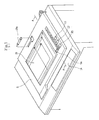
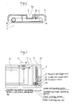
- Fig. 1 shows the structure and construction of the main portions of an analog or a digital image forming apparatus according to an embodiment of the present invention
- Fig. 1 (a) is a perspective view with the document pusher open
- Fig. 1 (b) is a perspective view with the document pusher closed
- Fig. 1 (c) is a sectional view taken along the line A - A' in Fig. 1 (b),
- Fig. 1 (d) is a plan view of the document pusher portion
- Fig. 1 (e) is a rough elevational view with the document pusher closed
- Fig. 1 (f) is a view equivalent to Fig. 1 (e) with the optical system scanned
- Fig. 2 is a block diagram showing one of the controlling systems of the analog or the digital image forming apparatus
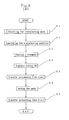
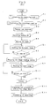
- Fig. 3 (a), (b), (c), (d), (e), (f) (g), and (h) are a flow chart showing one of the controlling procedures of the analog or the digital image forming apparatus, respectively.
- Fig. 4 and Fig. 5 show the structure and construction of the main portions of an analog or a digital image forming apparatus according to another embodiment of the present invention, respectively, and correspond to Fig. 1 (d).
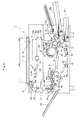
- Fig. 6 is a rough elevational view showing the whole configuration of one of the examples of an analog copying machine to which the present invention is applicable.
- Fig. 7 is a rough elevational view showing the whole configuration of one of the examples of a digital copying machines to which the present invention is applicable.
- An analog or a digital image forming apparatus can be so composed that only the image of mark can be transferred to a sheet of image transferring paper or both the image of a mark and the images of a document can be composed on a sheet of image transferring paper.
- a mark image can be transferred later on the sheet of image transferring paper to which the images of a document have been transferred. And it is needless to say that the document images can be transferred later on the sheet of image transferring paper on which the mark image has been transferred in advance.
- An analog image forming apparatus A shown in Fig. 6 is composed as a copying machine having three paper feeding sections of a hand paper feeding section 30a, paper feeding cassettes 30b and 30c at the right side thereof.
- a document table 4 is provided on the upper surface of the analog image forming apparatus A.
- a lamp unit 28 which can move from the solid line position 28 to the two-dashed line position 28a along this document table 4 scans a document placed on the document table 4.
- a recording medium 1 described later and mark travelling mechanism 2 (Fig. 1) of the drive system thereof are provided at the extreme downstream section in the exposure scanning direction shown with an arrow 31 of a document pusher 5 by which a document placed on the document table is pushed down.
- the recording medium 1 is exposed and scanned by the lamp unit 28 as described below.
- the light emitting from the lamp unit 28 is reflected by a document on the document table or the recording medium 1 and makes an incidence to a group of lens 29 by way of mirrors 32a, 32b, and 32c. Furthermore, it is imaged on the surface of a photosensitive body 33 via mirrors 32d, 32e and 32f and forms an electrostatic latent image, corresponding to the document image or the mark image on the recording medium 1, on the surface of the photosensitive body in accompanying with the rotation thereof.
- the electrostatic latent image is developed to toner image in a short time by either of a developer 34a or 34b (the developer 34b in the Figure) in accompanying with the rotation of the photosensitive body 33 and comes to the transfer section 36 opposite to a transfer charger 35.
- a sheet of image transferring paper which is sent out from either of the paper feeding sections 30a through 30c, for instance, the hand paper feeding section 30a, by a paper feeding roller 37, is inserted into a pair of resist rollers 39 through the feed roller 37a and temporarily comes to a stop.
- the resist rollers 39 send out a sheet of image transferring paper to the transferring portion 36 at an appointed timing from starting of the optical system including the lamp unit shown by the solid line position (home position).
- a toner image on a sheet of image transferring paper to which the toner image is transferred by the transfer section 36 is fixed at the fixing section 38.
- a pair of feed rollers 41a, a changer guide 40, a pair of feed rollers 41b, a changer guide 42, a delivery roller 43 and a delivery tray 44 are installed at the side of downstream of the fixing section 38.
- the changer guide 40 swings, centering around an axis 45, between the solid line position 40 and the two-dashed line position 40a, thereby causing the transferring direction of a sheet of image transferring paper to be changed.
- the sheet of image transferring paper which comes out from the fixing section 38 is delivered to the delivery tray 44 by means of the delivery roller 43 through pairs of feed rollers 41a and 41b and the changer guide 42.
- the changer guide 40 When making a transfer processing for only the mark described on the recording medium 1 or a document placed on the document table 4 only one time, the changer guide 40 is changed to the solid line position as shown in the above, and the sheet of image transferring paper receives only one-time transfer processing and is delivered to the delivery tray 44.
- a position of the changer guide 40 is changed to the two-dashed line position 40a before the sheet of image transferring paper is sent out by means of a pair of feed rollers 41a after having received the first-time transfer processing at the transfer section 36 and having received the fixing processing at the fixing section 38.
- the sheet of image transferring paper sent out by the pair of feed roller 41a is guided by the changer guide 40 and goes into the guide duct 46 arranged at the lower part. Furthermore, it is fed to the intermediate tray 48 from a pair of feed rollers 47.
- the leading edge of the sheet of image transferring paper which is sent out from the intermediate tray 48 through the pre-feed roller 49 and the paper re-feed roller 50 is inserted into a pair of resist rollers 39 by a pair of the feed rollers 51 again and the sheet of image transferring paper comes to a stop.
- the exposure scanning for a document or a mark on the recording medium 1 is executed by the lamp unit 28 and a pair of the resist rollers 39 begin to rotate in timing therewith, thereby causing a new image to be composed and transferred to the pre-transferred image.
- the changer guide 40 is changed to the position indicated with the solid line 40, and the sheet of image transferring paper on which a new image has been composed and transferred is sent to the fixing section 38 by a transfer belt 37.
- the sheet of image transferring paper is delivered to the delivery tray 44 from the delivery roller 43 through a pair of feed rollers 41a, a changer guide 40, a pair of feed rollers 41b, and a changer guide 42.
- a recording medium 1 indicated in Fig. 1 is for physically describing a plurality of optional marks, and, for instance, is composed of a detachable resin-based white belt. Therefore, even though a mark is described on the surface of the recording medium by a felt pen or a stamping method, the mark is erasable by wiping it off. So, it can be continuously used.
- the recording medium 1 is composed of for instance a paper belt. If it is replaced with a new paper belt after all the area on the recording medium is filled with marks, the deleting work of the marks described on the recoding medium can be saved.
- the recording medium 1 shown in the above is arranged outside the document placing area 4a of the document pusher 5 attached to the document table 4 indicated in Fig. 1 (d) and at the forward side of the sub scanning direction (the direction of an arrow 6) to the document from the home position of the optical system and is suspended to be endless on a pair of the rollers 7 and 8 (Fig. 1 (c)) which are oppositely arranged over the main scanning direction (the right angle to the arrow 6) of the document.
- a tablet 19 which is an already-known position designating means used for such edition as trimming, masking, etc. is provided in the document placing area 4a of the document pusher 5.
- An opening 5a for describing a mark is provided on the document pusher 5 corresponding to the upper portion of the recording medium 1, and a stamp plate 9 for supporting the recording medium 1 when describing a mark is provided at the underside of the recording medium corresponding to the opening 5a.
- the recording medium 1 is jogged or inched one after another per lengthwise dimension corresponding to the opening 5a by means of a stepping motor 10 which rotates the roller 7 whenever operating the increment switch 20 indicated in Fig. 1 (d).
- rollers 7 and 8, and the stepping motor 10 constitute the mark travelling mechanism 2 which drives and moves the recording medium 1.
- Mark selecting means 3 is for selecting one or two or more optional marks in the mark scanning area 4b (Fig. 1 (b)) of a plurality of marks described on the recording medium and is provided with a singularity mark changer switch 11 and a plurality mark changer switch 12.
- ten numerals keys (not illustrated herein) which are provided in advance in the operation board 14 of the analog image forming apparatus can be also utilized instead of the above ten numeral keys 13.
- the singularity mark changer switch 11 and the plurality mark changer switch 12 can be omitted by getting rid of such a feature as enabling two or more consecutive optional marks in the mark scanning area to be selected and constituting the system so that only a single mark can be usually selected.
- the recording medium 1 must travel by the mark travelling mechanism and the selected mark must be moved to the position of transfer in the sub scanning direction in order to transfer the mark selected by the mark selecting means to any optional position on the sheet of image transferring paper.
- the mark is moved to the position in which the ratio of magnification is taken into consideration in other cases than the equal ratio (the first controlling means).
- the initial position of the recording medium 1 is decided through detecting the reference line 17 provided on the recording medium 1 by for instance a reflection type phototube sensor 18. And a mark described on the recording medium 1 through the opening 5a can be moved to any optionally selected position which can be scanned by the optical system, by driving the stepping motor 10, standardizing the position of the reference line 17.
- presence or absence of a mark on the recording medium 1 is judged when incrementally moving the recording medium 1, by providing, for instance, a CCD (mark detecting means) for detecting the shape of a mark on the recording medium 1 instead of the phototube sensor 18 , and another mark can be described on the recording medium 1 as automatically stopping the blank area, corresponding to the opening 5a, skipping the area on which marks have been already described.
- a CCD mark detecting means
- the shape of a mark on the recording medium 1 can be directly detected, thereby causing the recording medium 1 not to be driven by standardizing the position of the reference line 17 by means of the phototube sensor 18 and causing the recording medium 1 to be quickly driven and traveled to an optional position in the main scanning direction which can be scanned by the optical system with reference to the position of the mark (the second controlling means).
- the paper feed timing for exposure scanning is adjusted.
- the position of describing (transferring) of the mark in relation to the sub scanning direction of the document is decided.
- the means for realizing such a feature is the paper feed timing adjusting means, and for instance it is realized by softwares or a timing circuit.
- the paper feed timing adjusting means According to the amount of the paper feed timing adjustment by the paper feed timing adjusting means and the position of a mark positioned by the first controlling means (or the second controlling means) in the main scanning direction, other images than in the mark portion selected by the mark selecting means are erased on the photosensitive body, and a feature for extracting only the image of the selected marks is the mark extracting means. As a result, unnecessary marks can be prevented from being transferred to the sheet of image transferring paper.
- the mark extracting means there are the following ways to embody the mark extracting means, i.e., (1) providing a blank lamp 22 at the portions on the surface of photosensitive body 23 corresponding to other images than the selected mark portions (refer to Fig. 6), (2) not bringing the exposed light of particular portions to the surface of the photosensitive body by means of a shutter, and (3) changing the width of charging of an electrifying charger by means of a shutter, etc.
- the first controlling means is so composed as to include a procedure for appointing the position of transferring of a mark and a procedure for driving the recording medium 1 up to the appointed position by controlling the mark travelling mechanism 2.
- the position of transferring of the selected mark is appointed by operating the tablet 19 arranged on the document pusher 5, and the position of transferring of the mark is decided by the X-Y coordinate system by pointing out the appointed position on the surface of the tablet 19 with a stylus pen 19a.
- a singularity mark changer switch 11, a plurality mark changer switch 12, ten numerals keys 13, an increment switch 20 for jogging or inching the recording means 1 pitch by pitch (equivalent to the dimension in relation to the lengthwise direction of the opening 5a) and a tablet 19 are arranged on the document pusher 5.
- parts having a function to transfer other marks than the document images onto a sheet of image transferring paper can be independently sold. It is preferable to extend the option of configuration thereof.
- a desired mark is manually described on the recording medium 1 through the opening 5a of the document pusher 5.
- One or more of such marks can be described through the opening 5a on the recording medium 1 which is advanced pitch by pitch whenever operating the increment switch 20.
- a mark to be transferred to a sheet of image transferring paper is selected in the step S1 (corresponding to the mark selecting means).
- a single mark to be transferred is selected by operating the key of a number corresponding to the mark to be transferred, of ten numeral keys 13 which expresses the sequence of describing of the plurality of marks (Step S1b).
- Step S1c a key of the number corresponding to the leading mark of the consecutive marks of the ten numeral keys 13 is operated (S1d) and furthermore a key of the number corresponding to the ending mark of the consecutive marks is operated (S1e).
- an appointed mark is moved to the position in alignment with the opening 5a by using the increment switch 20 and the appointed mark can be selected by operating a selector switch (not illustrated) or a transfer button is available instead of selecting a mark to be transferred by operating the ten numeral keys.
- the transferring position of the mark on the sheet of image transferring paper is decided on the X-Y coordinate system by pointing out the transferring position by means a stylus pen 19a on the tablet 19 shown in Fig. 2. Completion of pointing out the transferring position on the tablet 19 is notified to a control device by pressing down the selector switch or a transfer button provided in the vicinity of the tablet 19, and a mark which exists in the opening 5a is selected by pressing down these switches and/or buttons.
- a document can be placed on the document table 4 prior to the action in the step S1.
- step S5 the first-time transfer processing is executed (corresponding to the usual transfer means).
- the optical system 27 moves to the document placed on the document table 4, and the image thereof is scanned by the optical system 27 and is transferred to the sheet of image transferring paper.
- the sheet of image transferring paper is temporarily stored in the intermediate tray 48.
- the recording medium 1 is driven and transferred (corresponding to the first controlling means) by controlling and driving the stepping motor 10.
- the mark selected in the step S1 is moved to the transferring position in relation to the main scanning direction, appointed by using the tablet 19 in the step S2, which is the position scannable by the optical system 27.
- the sheet of image transferring paper which is temporarily stored in the intermediate tray 48 is fed again.
- the blank lamp 22 is controlled. Then, rejection exposure is given to the surface of the photosensitive body 33 corresponding to other images than those at the selected mark portion according to the amount of "ON" timing adjustment of the paper feed clutch 21 and the position of the mark specified in the step S6 in the main scanning direction. As a result, only the necessary mark images can be transferred to the position on the sheet of image transferring paper appointed by the tablet 19. Namely, the mark images can be composed together with the document images transferred in the step S5.
- an optional mark can be transferred and copied on the sheet of image transferring paper in a remarkably simple manner without re-inserting a card on which a mark is described in the case of a conventionally known apparatus.
- the mark images are composed to the document images by the usual transfer means (Step S5).
- the transfer processing in the step S5 is omitted, independent mark image can be transferred on the sheet of image transferring paper.
- all the marks described in the recording medium 1 can be easily seen by installing a transparent sight window 23 at the position of installation of the recording medium 1 as shown in Fig. 4, thereby causing an optional mark to be selected easily.
- the ten numeral keys 13 can be omitted when a transparent touch panel 24 by which all the marks described in the recording medium 1 can be sighted is provided, and when such a construction that an optional mark can be selected by operating the portion on the transparent touch panel 24 corresponding to the mark, then it is possible to select any optional mark in further simple manner.
- the principal parts, including the recording medium 1, of a feature by which other marks than the document images can be transferred to to the sheet of image transferring paper can be removably installed on the document pusher 5.
- a specified mode for always transferring a mark for instance, at the central position in the main scanning direction at the forward end or the backward end of the sheet of image transferring paper can be provided in addition to specifying the mark transfer position on the X-Y coordinate system by means of position appointing means 19 like the tablet 19.
- the second embodiment explained hereinafter relates to an analog image forming apparatus in which the document images can be composed to the mark images only with one-time exposure scanning, and the magnification of the mark images is variable. Also, the factors and members which are common to the constitution of the first preferred embodiment are given the same reference numbers and the explanation thereof is omitted.
- a home position switch 26 (H.P. SW2, the second detecting means) is further given, as shown in Fig. 1 (e), (f) and Fig. 2, in addition to a home position switch 25 (H.P. SW1, the first detecting means) for detecting the starting point of the travelling of the light source when the light source makes exposure scanning for usual documents.
- the home position switch 25 is for detecting the first origin position of scanning of the optical system 27 (in details, the lamp unit 28 which constitutes the optical system 27) for the document placing area 4a on the document table 4 which is divided into the document placing area 4a and the mark scanning area 4b.
- a contact type limit switch or a non-contact type reflection phototube sensor, etc. may be used as this home position switch 25.
- the home position switch 26 is arranged in the vicinity of the boundary portion between the document placing area 4a and the mark scanning area 4b and is for detecting the second origin position of scanning of the optical system 27 for the mark scanning area 4b.
- a contact type limit switch or a non-contact type reflection phototube sensor, etc. may be used as home position switch 26.
- the marks are described on the recording medium 1 and those to be transferred are selected (N1, S1a, S1b, S1c, S1d, S1e) by the same operation as those in the first preferred embodiment.
- Step S2a the ratio of magnification or reduction of the mark images to the sheet of image transferring paper is firstly pointed out by operating the ten numeral keys on the operation panel 14.
- Step S2b the reference point on the sheet of image transferring paper on which the mark images are to be transferred is appointed (Step S2b) by indicating the transfer position at one point by means of a stylus pen on the tablet as well as in the above case.
- a document can be placed on the document table 4 prior to action in the step N1.
- the recording medium 1 is driven and moved by controlling and driving the stepping motor 1 in the step N5.
- the mark selected in the step N1 is moved to the transfer position, where the mark can be scanned by the optical system 27, in relation to the main scanning direction responsive to the ratio of magnification or reduction and the reference point appointed in the step N2.
- the transfer position must be moved in response to the ratio of magnification or reduction by adjusting the paper feed timing, which described later.
- the travelling position of the recording medium 1 in the main scanning direction should be computed and operated in taking the ratio of magnification or reduction into consideration, and it is necessary to further adjust the paper feed timing of a sheet of image transferring paper, described later, only by the amount of biasing in the sub scanning direction by the set ratio of magnification or reduction.
- the optical system 27 is moved for scanning from the first origin position of scanning of the optical system 27 detected by the home position switch 25 in the step N6, and the image of a document placed in the document placing area 4a is transferred to a sheet of image transferring paper.
- the transfer operation in this step N6 has no difference from usual transfer processing and is the same as those of the usual transfer means in the first preferred embodiment on which the ratio of magnification or reduction has been taken into consideration.
- the optical system 27 does not return in the direction of the home position switch 25 but goes toward the mark scanning area 4b.
- the lamp unit 28 of the optical system 27 temporarily makes a pause at the position detected by the home position switch 26 (Steps N7 and N8) to cause the sheet of image transferring paper to be temporarily accommodated in the intermediate tray 48 (outside the Figure).
- the sheet of image transferring paper which is temporarily accommodated in the intermediate tray 48 is sent out toward the photosensitive body again and it temporarily comes to a stop when the leading edge thereof is inserted into a pair of the resist rollers 39 (Step N9).
- step N10 the paper feed timing of the sheet of image transferring paper is adjusted.
- a group of lens 29 and mirrors 32d, 32e, etc. for changing the ratio of magnification or reduction, which constitute the optical system 27, are reasonably moved and adjusted in response to the ratio of magnification or reduction.
- the "ON" timing of the paper feed clutch 21 for the exposure scanning by the optical system 27 is adjusted, and the reference point on the mark on the sheet of image transferring paper for the sub scanning direction and the transferring position according to the ratio of magnification or reduction are decided.
- the sheet of image transferring paper is fed again.
- the lamp unit 28 is subjected to scanning from the second origin position of scanning of the lamp unit 28 of the optical system 27 detected by the home position switch 26, thereby causing the selected mark to be transferred to an appointed position (i.e., the area on the basis of the reference point) on the sheet of image transferring paper on which the document image has been transferred.
- the blank lamp 22 is controlled when making the transfer processing, and the rejection exposure is made at the portion of the surface of the photosensitive body 22 corresponding to other images than those in the mark portion selected in the above, in response to the amount of "ON" timing adjustment of the paper feed clutch 21 and the position of the mark specified in the step N5 in the main scanning direction.
- the mark image of the required ratio of magnification or reduction can be transferred to the desired position, pointed out by the tablet 19, on the sheet of image transferring paper.
- the lamp unit 28 of the optical system 27 returns to the position detected by the home position switch 25 (in the steps N12 and N13).
- the image of a document is transferred to the sheet of image transferring paper by letting the lamp unit 28 scan from the first origin position of scanning of the lamp unit 28 of the optical system 27, and furthermore the mark images can be transferred to the sheet of image transferring paper by letting the lamp unit 28 scan from the second origin position of scanning without that the lamp unit 28 returns to the first origin position of scanning. Therefore, the time required for the lamp unit 28 to travel over the distance "L" in the lengthwise direction of the document placing area 4a can be saved, thereby causing the time of actuation of lamp unit 28 and the distance of action thereof to be shortened.
- the travelling amount of the recording medium 1, i.e., of the mark is determined by pointing out the reference position for transferring the mark and the ratio of magnification or reduction when making a transfer with the ratio of magnification or reduction changed.
- the ratio of magnification or reduction can be operated by pointing out the mark scanning area on the sheet of image transferring paper, and the travelling amount of the mark can be determined on the basis of the ratio of magnification or reduction operated therein.
- Means for accomplishing this feature is the area appointing means and the magnification (or reduction) ratio operating means described below.
- the area appointing means is embodied by a tablet 19 as position appointing means described later in the apparatus according to this embodiment.
- the transferring position on the sheet of image transferring paper is specified by pointing out two area appointing points of, for instance, the left upper edge and the right lower edge of the area of an mark image to be transferred.
- the transferring position can be specified in the X-Y coordinate system by operating the ten numeral keys on the operation panel 14 instead of the tablet 19.
- the magnification (or reduction) ratio operating means is for operating the ratio of magnification or reduction of the mark image to the sheet of image transferring paper on the basis of the transferring position of the mark appointed by the area appointing means. And this ratio of magnification or reduction can be computed and operated by comparing the area of the opening 5a and the area of a markimage to be transferred to the sheet of image transferring paper.
- the area appointing means and the magnification (or reduction) ratio operating means are realized as the steps S2c and S2d in Fig. 3 (f), i.e., as appointing procedure of the transferring position (area) of the selected mark on the sheet of image transferring paper.
- the transferring area on the sheet of image transferring paper, on which the image of the mark is to be transferred is pointed out by indicating the transferring position at two points by using a stylus pen 19a on the tablet 19 (Step S2c in Fig. 3 (f)).
- the ratio of magnification or reduction of the image of the mark is calculated.
- the balance of the image of the mark to the image of the document is made reasonable by making the size of the mark to be transferred to the sheet of image transferring paper optionally variable.
- the digital duplicating machine which is one of the examples of a digital image forming apparatus B shown in Fig. 7 stores optical image data obtained by scanning a document through exposing light thereto in a memory as digital signals, takes out the image data by searching for this memory according to the necessity, drives a laser device according to the digital image data, and forms electrostatic latent image on a photosensitive body by light diffusion means like a polygon mirror, etc.
- this digital image forming apparatus is different from an analog image forming apparatus A shown in Fig.
- the third embodiment shown below copes with the example of such a construction that the mark images and the document images can be composed on a sheet of image transferring paper.
- the recording medium 1, arrangement thereof, and drive mechanism thereof, etc. which are utilized in the third embodiment are the same as those used in the first preferred embodiment and are as shown in Fig. 1 (a) through (c). The detailed description thereof is omitted herein.
- the mark selecting means for selecting one or two or more marks of a plurality of the marks described on the recording medium 1 and the mark travelling mechanism for driving and travelling the belt-like recording medium 1 to move the mark(s) selected by the mark selecting means are the same as those shown in the first embodiment. Therefore, the description thereof is omitted herein.
- the third and the fourth controlling means for controlling the mark travelling mechanism and for driving the recording medium to an optional position is the same as the first controlling means that is described in relation to the first embodiment, the explanation thereof is also omitted herein.
- a primary line sensor CCD for converting the images obtained by scanning of the optical system as shown in the above to electric signals is utilized.
- the optical system can expose light to and can scan a document placed on the document table 4 as a matter of course and a mark described on the recording medium 1. Therefore, the primary line sensor CCD can read both the document and the mark, separately.
- the analog image data read by the primary line sensor CCD is converted to digital image data by an analog/digital converter (A/D converter) (outside the Figures) and is memorized in a digital graphical memory outside the Figures.
- image reading means consists of the primary line sensor CCD, an A/D converter and the graphical sensor.
- the image reading means can read only the mark. At this time, it can be named as mark reading means.
- the data of the mark image, selected by the mark selecting means, of the mark images read by the image reading means (or the mark reading means) is extracted in the memorized memory map (by the data extracting means. For instance, after the data is once escaped in a separate memory, it is processed and composed together with the data of the document image which has been read in advance (corresponding to the composing processing means).
- the image data which is obtained by the composing processing, equivalent to one sheet of the sheet of recording paper is outputted to the laser device responsive to the recording position on the sheet of recording paper, thereby causing the transfer processing to be successfully executed.
- the recording position of a mark on a sheet of recording paper can be fixedly set in advance when making the record processing by the record processing means, the data of the mark image, whose mark data extracted corresponding to the position appointing means 19 like the tablet, etc. for pointing out the recording position of a mark on the sheet of recording paper can be outputted for recording processing so that setting of the position of the mark can be promptly changed in a simple manner as shown in the apparatus of this embodiment.
- a desired mark is manually described on the recording medium 1 through the opening 5a of the document pusher 5.
- One or more of such marks can be described through the opening 5a on the recording medium 1 which is advanced pitch by pitch whenever operating the increment switch 20.
- a mark to be recorded on the sheet of recording paper is selected in the step J1 (Refer to Fig. 3 (g)) (corresponding to the mark selecting means).
- Step S1a a single mark to be recorded is selected by operating the key of a number corresponding to the mark to be recorded, of ten numeral keys 13 which expresses the sequence of describing of the plurality of marks.
- Step S1c a key of the number corresponding to the leading mark of the consecutive marks of the ten numeral keys 13 is operated (S1d) and furthermore a key of the number corresponding to the ending mark of the consecutive marks is operated (S1e).
- the recording position of the mark on the sheet of recording paper is pointed out in the step J2.
- the recording position of the mark on the sheet of recording paper is specified in the X-Y coordinate system by pointing out the recording position by means of a stylus pen on the tablet shown in Fig. 2.
- step J3 a document is placed on the document table 4. And in the step J4, the recording button is operated.
- a document can be placed on the document table 4 prior to action in the step J1.
- the recording medium 1 is driven and moved by controlling and driving the stepping motor 10 (The third controlling means).
- the mark selected in the step J1 is moved to the position where it can be read by an image reading means 55 (lamp unit 28, mirrors 32a through 32c, a group of lens 29 and CCD).
- the image reading means 55 moves relatively to the document, thereby causing the image of the mark on the recording medium 1 and the image of the document placed on the document table 4 to be read by the image reading means 55.
- the data thus read in the above is temporarily memorized in the memory.
- the data of the mark image, selected by the mark selecting means, of the image data which is temporarily memorized in the above is extracted (corresponding to the fourth data extracting means), and the data of the extracted mark image and the data of the document image can be processed and composed (corresponding to the composing processing means).
- the data is processed in the memory map, corresponding to the mark recording position appointed in the step J2.
- step J8 the image data processed and composed in the step J7 is outputted, corresponding to the recording position on the sheet of recording paper for recording and processing (corresponding to the second recording/ processing means).
- the paper feed clutch 21 is turned on at an appointed timing and a sheet of recording paper is fed to the recording section (transfer section 36), and the image of the document is recorded on the sheet of recording paper, and at the same time the selected mark is also recorded at the appointed position on the sheet of recording paper.
- an optional mark can be transferred to a sheet of recording paper in a remarkably simple manner without re-inserting a card on which a mark is described as shown for the conventional apparatus.
- a digital image forming apparatus it is possible to select any of optional marks by directly sighting all the marks described on the recoding medium 1 if a transparent sight window 23 is provided at the installation position of a recording medium 1 as shown in Fig. 4, too.
- a digital image forming apparatus as shown in Fig. 5, it is possible to select an appointed mark in a further simple manner if the system is so composed that the ten numeral keys 13 can be omitted and a transparent touch panel 24 by which all the marks described on the recording medium 1 can be seen can be installed and an optional mark can be selected by operating the portion on the transparent touch panel 24.
- the main portion of a feature for transferring other marks, including the recoding medium 1, than the document images on a sheet of recording paper can be removably provided on the document pusher 5.
- a specified mode by which a mark is usually transferred to the central position in the main scanning direction at the front leading side and/or the rear ending side of a sheet of recording paper can be provided in addition to specifying the recording position of a mark on the X-Y coordinate system by the position appointing means (tablet) 19.
- the home position unique to the mark image is provided, thereby causing the position detecting accuracy of the mark image to be heightened. Also, the ensuing description copes with a digital image forming apparatus in which the mark image can be promptly magnified or reduced.
- FIG. 1 (e), (f) and Fig. 2 another home position switch 26 (H.P. SW2, the second detecting means) is provided in addition to the home position switch 25 (H.P. SW1, the first detecting means) for detecting the starting point of a light source movement when the light source makes an exposure scanning for a usual document.
- H.P. SW2 the second detecting means
- Such a home position switch 26 (H.P., SW2) is of the same construction as that which is used for the second embodiment.
- the home position 26 is arranged in the vicinity of the boundary portion between the document placing area 4a an the mark scanning area 4b, and is for detecting the second origin position of movement of the image reading means 55 in connection to the mark scanning area 4b.
- a contact type limit switch or a non-contact type reflection phototube sensor, etc. may be used as this home position switch 26.
- the ratio of magnification or reduction of the mark image for the sheet of recording paper can be inputted by operating the ten numeral keys in the operation panel 14 (magnification (or reduction) ratio appointing means).
- the mark reading means is for moving the lamp unit 28 from the second origin position of movement, which is detected by the home position switch 26, and for reading the mark images according to patterns on the basis of each data of the ratio of magnification (or reduction) appointed by the magnification (or reduction) ratio appointing means and the reference point appointed by the reference point appoint means described later by promptly adjusting the image reading means 55 and/or the position in the main scanning direction of the mark image described on the sheet of recording paper.
- the mark images can be recorded on a sheet of recording paper at equal ratio without any magnification or reduction by appointing the ratio of magnification (or reduction) to "1" or omitting the magnification (or reduction) appointing means or the reference point appointing means.
- a program shown in Fig. 3 (h) is executed as main routine.
- the lamp unit 28 is moved from the first origin position of moving of the lamp unit, which is detected by the home position switch 25, thereby causing the image of a document placed on the document placing area 4a to be read (corresponding to the document reading means).
- the lamp unit 28 makes a pause at the point when the second origin point is detected by the home position switch H.P. SW2 (the steps K7 and K8).
- a group of the lens 29, etc. and the recording medium 1 are moved and controlled. Also, in this case, the recording medium 1 can be moved prior to movement of the lamp unit 28.
- the reference point appointing means is for appointing the reference point on the sheet of recording paper on which the mark image is to be recorded.
- the reference point appointing means is embodied by a tablet 19.
- the reference point can be specified on the X-Y coordinate system by operating the ten numeral keys in the operation panel 14 instead of the tablet 19.
- the lamp unit 28 is moved from the second origin point of movement of the lamp unit 28, which is detected by the home position switch 26, thereby causing the mark images to be read (in the step K9).
- Each of the data read as shown in the above is temporarily memorized in a memory. And the lamp unit 28 of the image forming device 27 which has completed the action of reading the images returns to the first origin point of movement, which is detected by the home position switch 25 (in the steps K10 and K11).
- the data of the mark images, selected by the mark setting means 3, of the mark images temporarily memorized as shown in the above is extracted. Then, the data of this extracted mark image can be processed and composed together with the data of the document images.
- the data is processed in the memory map, corresponding to the mark recording position and the ratio of magnification (or reduction) appointed in the step K2.
- the image data processed and composed in the step K12 is outputted to the recording position on the sheet of recording paper, thereby causing the recording thereof to be processed and executed.
- the paper feed clutch 21 is turned on at an appointed timing and a sheet of recording paper is fed toward the recording section. And the image of a document is recorded on the sheet of recording paper. At the same time, the selected mark is recorded at an appointed position on the sheet of recording paper according to the appointed ratio of magnification (or reduction).
Landscapes
- Engineering & Computer Science (AREA)
- Multimedia (AREA)
- Signal Processing (AREA)
- Physics & Mathematics (AREA)
- General Physics & Mathematics (AREA)
- Facsimile Scanning Arrangements (AREA)
- Control Or Security For Electrophotography (AREA)
Priority Applications (1)
| Application Number | Priority Date | Filing Date | Title |
|---|---|---|---|
| EP94106419A EP0610968A1 (de) | 1989-12-13 | 1990-12-10 | Bilderzeugungsgerät |
Applications Claiming Priority (8)
| Application Number | Priority Date | Filing Date | Title |
|---|---|---|---|
| JP323581/89 | 1989-12-13 | ||
| JP323582/89 | 1989-12-13 | ||
| JP1323581A JPH03182779A (ja) | 1989-12-13 | 1989-12-13 | アナログ画像形成装置 |
| JP1323582A JPH03182780A (ja) | 1989-12-13 | 1989-12-13 | デジタル画像形成装置 |
| JP135813/90 | 1990-05-25 | ||
| JP2135813A JPH0429262A (ja) | 1990-05-25 | 1990-05-25 | デジタル画像形成装置 |
| JP2135812A JPH0429261A (ja) | 1990-05-25 | 1990-05-25 | アナログ画像形成装置 |
| JP135812/90 | 1990-05-25 |
Related Child Applications (1)
| Application Number | Title | Priority Date | Filing Date |
|---|---|---|---|
| EP94106419.8 Division-Into | 1990-12-10 |
Publications (3)
| Publication Number | Publication Date |
|---|---|
| EP0435053A2 true EP0435053A2 (de) | 1991-07-03 |
| EP0435053A3 EP0435053A3 (en) | 1991-12-18 |
| EP0435053B1 EP0435053B1 (de) | 1995-04-19 |
Family
ID=27471953
Family Applications (2)
| Application Number | Title | Priority Date | Filing Date |
|---|---|---|---|
| EP94106419A Withdrawn EP0610968A1 (de) | 1989-12-13 | 1990-12-10 | Bilderzeugungsgerät |
| EP90123695A Expired - Lifetime EP0435053B1 (de) | 1989-12-13 | 1990-12-10 | Bilderzeugungsgerät |
Family Applications Before (1)
| Application Number | Title | Priority Date | Filing Date |
|---|---|---|---|
| EP94106419A Withdrawn EP0610968A1 (de) | 1989-12-13 | 1990-12-10 | Bilderzeugungsgerät |
Country Status (3)
| Country | Link |
|---|---|
| US (1) | US5146275A (de) |
| EP (2) | EP0610968A1 (de) |
| DE (1) | DE69018800T2 (de) |
Cited By (1)
| Publication number | Priority date | Publication date | Assignee | Title |
|---|---|---|---|---|
| EP0596706A1 (de) * | 1992-11-05 | 1994-05-11 | Xerox Corporation | Verfahren und Vorrichtung zum Speichern und Drucken von Logos |
Families Citing this family (5)
| Publication number | Priority date | Publication date | Assignee | Title |
|---|---|---|---|---|
| JP3142428B2 (ja) * | 1993-12-13 | 2001-03-07 | 株式会社東芝 | 画像形成装置 |
| US7016551B1 (en) * | 2000-04-10 | 2006-03-21 | Fuji Xerox Co., Ltd. | Image reader |
| JP4174282B2 (ja) * | 2002-10-01 | 2008-10-29 | キヤノン株式会社 | 画像読取装置 |
| US7636177B2 (en) * | 2004-04-23 | 2009-12-22 | Xerox Corporation | Systems and methods for forming composite images with digital graphic elements |
| WO2006070476A1 (ja) * | 2004-12-28 | 2006-07-06 | Fujitsu Limited | 画像内の処理対象の位置を特定する画像処理装置 |
Family Cites Families (10)
| Publication number | Priority date | Publication date | Assignee | Title |
|---|---|---|---|---|
| DE2244961C3 (de) * | 1972-09-13 | 1980-11-13 | Agfa-Gevaert Ag, 5090 Leverkusen | Kopiergerät zum Übereinanderkopieren von Datenblättern und Masken |
| US3930724A (en) * | 1973-11-12 | 1976-01-06 | Xerox Corporation | Masking apparatus for a multi-color electrophotographic printing machine |
| JPS6021368B2 (ja) * | 1977-05-19 | 1985-05-27 | キヤノン株式会社 | 画像形成装置の従情報写込み機構 |
| JPS5454041A (en) * | 1977-10-07 | 1979-04-27 | Ricoh Co Ltd | Compliex image formation |
| US4637707A (en) * | 1983-12-28 | 1987-01-20 | Konishiroku Photo Industry Co., Ltd. | Supplementary data copying method and original picture image recorder having supplementary data display means |
| JPS6244730A (ja) * | 1985-08-23 | 1987-02-26 | Minolta Camera Co Ltd | 原稿搬送装置 |
| JPS6327159A (ja) * | 1986-07-19 | 1988-02-04 | Sharp Corp | 記録装置 |
| US4989042A (en) * | 1987-02-26 | 1991-01-29 | Canon Kabushiki Kaisha | Image synthesizing apparatus |
| US4989038A (en) * | 1988-08-18 | 1991-01-29 | Sharp Kabushiki Kaisha | Image forming apparatus utilizing a light image memory |
| JPH0253775A (ja) * | 1988-08-18 | 1990-02-22 | Nissan Chem Ind Ltd | ピラゾールカルボキサミド誘導体及び除草剤 |
-
1990
- 1990-12-10 EP EP94106419A patent/EP0610968A1/de not_active Withdrawn
- 1990-12-10 DE DE69018800T patent/DE69018800T2/de not_active Expired - Fee Related
- 1990-12-10 EP EP90123695A patent/EP0435053B1/de not_active Expired - Lifetime
- 1990-12-11 US US07/625,850 patent/US5146275A/en not_active Expired - Fee Related
Cited By (2)
| Publication number | Priority date | Publication date | Assignee | Title |
|---|---|---|---|---|
| EP0596706A1 (de) * | 1992-11-05 | 1994-05-11 | Xerox Corporation | Verfahren und Vorrichtung zum Speichern und Drucken von Logos |
| US5452094A (en) * | 1992-11-05 | 1995-09-19 | Xerox Corporation | Method and apparatus for storage and printing of logos using a storage medium capable of storing multiple logos |
Also Published As
| Publication number | Publication date |
|---|---|
| DE69018800T2 (de) | 1995-11-30 |
| EP0610968A1 (de) | 1994-08-17 |
| EP0435053A3 (en) | 1991-12-18 |
| EP0435053B1 (de) | 1995-04-19 |
| US5146275A (en) | 1992-09-08 |
| DE69018800D1 (de) | 1995-05-24 |
Similar Documents
| Publication | Publication Date | Title |
|---|---|---|
| US4371898A (en) | Composite information recording apparatus | |
| US4494862A (en) | Computerized information processing system equipped with copying apparatus | |
| EP0325415B1 (de) | Kopier-Dokumentenzuführvorrichtung mit verstellbarem Ausrichtungssystem, einstellbar durch den Benutzer | |
| US4992827A (en) | Image forming apparatus | |
| US4627707A (en) | Copier with image editing function | |
| EP0489173B1 (de) | Abbildungsvorrichtung | |
| EP0180984B1 (de) | Bilderzeugungsgerät mit selektivem Bilderzeugungsbereich | |
| US4707126A (en) | Method of positioning original image to be copied and apparatus for performing the same | |
| US4696563A (en) | Split scanning copier | |
| JPS6352382B2 (de) | ||
| US5146275A (en) | Composite image forming apparatus | |
| US4340295A (en) | Composite information recording device | |
| US4742373A (en) | Copying machine | |
| US4746953A (en) | Membrane strip control | |
| US5708935A (en) | Simplified automated duplex margin repositioning system for different size originals | |
| US6097852A (en) | Image forming apparatus and method with modes for copying an entire extent of a document and an extent except for edge portions | |
| US4745443A (en) | Copying apparatus | |
| JPS6230429B2 (de) | ||
| JP3007753B2 (ja) | 原稿サイズ検知装置 | |
| US6862119B1 (en) | Image reading device | |
| US5666609A (en) | Copying machine and method for copying a designated area of an original document | |
| US5008704A (en) | Method of forming original image and additional image, and apparatus for performing same | |
| US4910537A (en) | Image forming apparatus | |
| JPH0867410A (ja) | 手差し給紙装置 | |
| JPS60239721A (ja) | 複写装置 |
Legal Events
| Date | Code | Title | Description |
|---|---|---|---|
| PUAI | Public reference made under article 153(3) epc to a published international application that has entered the european phase |
Free format text: ORIGINAL CODE: 0009012 |
|
| 17P | Request for examination filed |
Effective date: 19901231 |
|
| AK | Designated contracting states |
Kind code of ref document: A2 Designated state(s): DE FR GB IT NL |
|
| PUAL | Search report despatched |
Free format text: ORIGINAL CODE: 0009013 |
|
| AK | Designated contracting states |
Kind code of ref document: A3 Designated state(s): DE FR GB IT NL |
|
| 17Q | First examination report despatched |
Effective date: 19930405 |
|
| GRAA | (expected) grant |
Free format text: ORIGINAL CODE: 0009210 |
|
| AK | Designated contracting states |
Kind code of ref document: B1 Designated state(s): DE FR GB IT NL |
|
| XX | Miscellaneous (additional remarks) |
Free format text: TEILANMELDUNG 94106419.8 EINGEREICHT AM 10/12/90. |
|
| ITF | It: translation for a ep patent filed | ||
| REF | Corresponds to: |
Ref document number: 69018800 Country of ref document: DE Date of ref document: 19950524 |
|
| ET | Fr: translation filed | ||
| PG25 | Lapsed in a contracting state [announced via postgrant information from national office to epo] |
Ref country code: GB Effective date: 19951210 |
|
| PLBE | No opposition filed within time limit |
Free format text: ORIGINAL CODE: 0009261 |
|
| STAA | Information on the status of an ep patent application or granted ep patent |
Free format text: STATUS: NO OPPOSITION FILED WITHIN TIME LIMIT |
|
| 26N | No opposition filed | ||
| PG25 | Lapsed in a contracting state [announced via postgrant information from national office to epo] |
Ref country code: NL Effective date: 19960701 |
|
| GBPC | Gb: european patent ceased through non-payment of renewal fee |
Effective date: 19951210 |
|
| PG25 | Lapsed in a contracting state [announced via postgrant information from national office to epo] |
Ref country code: FR Effective date: 19960830 |
|
| NLV4 | Nl: lapsed or anulled due to non-payment of the annual fee |
Effective date: 19960701 |
|
| PG25 | Lapsed in a contracting state [announced via postgrant information from national office to epo] |
Ref country code: DE Effective date: 19960903 |
|
| REG | Reference to a national code |
Ref country code: FR Ref legal event code: ST |
|
| PG25 | Lapsed in a contracting state [announced via postgrant information from national office to epo] |
Ref country code: IT Free format text: LAPSE BECAUSE OF NON-PAYMENT OF DUE FEES;WARNING: LAPSES OF ITALIAN PATENTS WITH EFFECTIVE DATE BEFORE 2007 MAY HAVE OCCURRED AT ANY TIME BEFORE 2007. THE CORRECT EFFECTIVE DATE MAY BE DIFFERENT FROM THE ONE RECORDED. Effective date: 20051210 |