EP0435114A2 - Procédé pour commander la pression de freinage dans les freins des roues arrières d'un véhicule à deux ornières - Google Patents
Procédé pour commander la pression de freinage dans les freins des roues arrières d'un véhicule à deux ornières Download PDFInfo
- Publication number
- EP0435114A2 EP0435114A2 EP90124249A EP90124249A EP0435114A2 EP 0435114 A2 EP0435114 A2 EP 0435114A2 EP 90124249 A EP90124249 A EP 90124249A EP 90124249 A EP90124249 A EP 90124249A EP 0435114 A2 EP0435114 A2 EP 0435114A2
- Authority
- EP
- European Patent Office
- Prior art keywords
- brake
- pressure
- wheel
- unstable
- stable
- Prior art date
- Legal status (The legal status is an assumption and is not a legal conclusion. Google has not performed a legal analysis and makes no representation as to the accuracy of the status listed.)
- Granted
Links
- 238000000034 method Methods 0.000 title claims abstract description 13
- 230000000977 initiatory effect Effects 0.000 claims abstract description 4
- 230000000694 effects Effects 0.000 description 3
- 230000006399 behavior Effects 0.000 description 2
- 238000002347 injection Methods 0.000 description 2
- 239000007924 injection Substances 0.000 description 2
- 238000005259 measurement Methods 0.000 description 2
- 230000004048 modification Effects 0.000 description 2
- 238000012986 modification Methods 0.000 description 2
- 230000000903 blocking effect Effects 0.000 description 1
- 238000011156 evaluation Methods 0.000 description 1
- 238000005457 optimization Methods 0.000 description 1
- 230000000717 retained effect Effects 0.000 description 1
- 230000028838 turning behavior Effects 0.000 description 1
Images

Classifications
-
- B—PERFORMING OPERATIONS; TRANSPORTING
- B60—VEHICLES IN GENERAL
- B60T—VEHICLE BRAKE CONTROL SYSTEMS OR PARTS THEREOF; BRAKE CONTROL SYSTEMS OR PARTS THEREOF, IN GENERAL; ARRANGEMENT OF BRAKING ELEMENTS ON VEHICLES IN GENERAL; PORTABLE DEVICES FOR PREVENTING UNWANTED MOVEMENT OF VEHICLES; VEHICLE MODIFICATIONS TO FACILITATE COOLING OF BRAKES
- B60T8/00—Arrangements for adjusting wheel-braking force to meet varying vehicular or ground-surface conditions, e.g. limiting or varying distribution of braking force
- B60T8/17—Using electrical or electronic regulation means to control braking
- B60T8/176—Brake regulation specially adapted to prevent excessive wheel slip during vehicle deceleration, e.g. ABS
- B60T8/1764—Regulation during travel on surface with different coefficients of friction, e.g. between left and right sides, mu-split or between front and rear
-
- B—PERFORMING OPERATIONS; TRANSPORTING
- B60—VEHICLES IN GENERAL
- B60T—VEHICLE BRAKE CONTROL SYSTEMS OR PARTS THEREOF; BRAKE CONTROL SYSTEMS OR PARTS THEREOF, IN GENERAL; ARRANGEMENT OF BRAKING ELEMENTS ON VEHICLES IN GENERAL; PORTABLE DEVICES FOR PREVENTING UNWANTED MOVEMENT OF VEHICLES; VEHICLE MODIFICATIONS TO FACILITATE COOLING OF BRAKES
- B60T8/00—Arrangements for adjusting wheel-braking force to meet varying vehicular or ground-surface conditions, e.g. limiting or varying distribution of braking force
- B60T8/32—Arrangements for adjusting wheel-braking force to meet varying vehicular or ground-surface conditions, e.g. limiting or varying distribution of braking force responsive to a speed condition, e.g. acceleration or deceleration
Definitions
- the invention relates to a method for controlling the brake pressure in the brakes of the rear wheels of a two-track vehicle, in which the rotational speeds of at least the rear wheels are measured and the brake pressure is reduced, kept constant or built up as a function of unstable and stable conditions occurring on the individual rear wheels, whereby at least at times the braking pressure of a stable rear wheel is approximated to the braking pressure of an unstable rear wheel.
- Such a method is also referred to as "select low” because the rotational behavior of a so-called “low” wheel is used to also control the brake pressure in the brake of the so-called “high” wheel. This prevents a too strong torque about the vertical axis of the vehicle from occurring on the rear axle with different friction coefficients between the left and right rear wheels, which would take away the driving stability of the vehicle.
- a large number of algorithms for controlling the brake pressure in an anti-lock vehicle brake system are known.
- the measuring devices, valves and control devices required to carry out an ABS brake control are also known in a variety of configurations.
- New procedures To control the brake pressure in ABS systems are implemented using appropriate measuring and control devices (speed sensors, valves, etc.) by appropriate programming of a processor.
- a pure "select-low" control of the type described above has the advantage of good driving stability of the vehicle, but has the disadvantage that braking distance is wasted because the stable rear wheel could be braked more. By reducing the pressure on the stable rear wheel, there is also an increased difference in braking torque on the rear axle, which is also caused by a slip on the so-called "low wheel”.
- DE-OS 28 30 580 describes an anti-lock brake system in which a "select-low” control is modified such that the time span for an initial injection of brake pressure into the brake of the so-called “high wheel” in comparison with the brake pressure injection on the so-called “low wheel” is extended.
- DE-OS 28 12 000 also describes a modification of a "select-low" control.
- the brake pressure on the so-called “high wheel” ie the wheel running at a higher coefficient of friction
- the brake pressure on the so-called “high wheel” is first kept constant for a fixed period of time and then increased pulsatingly.
- DE-PS 28 51 107 proposes to reduce the brake pressure in the brake of the "high wheel” only when the "low wheel” has become stable again.
- the aim of the invention is to provide a method for controlling the brake pressures in the brakes of the rear wheels of a two-lane vehicle, with which the shortest possible braking distance with the best possible stability of the vehicle is achieved even with different friction coefficients of the road.
- the invention solves this problem in that after initiating a pressure reduction in the brake of an unstable rear wheel, the pressure in the brake of the stable rear wheel is kept constant for a predetermined period of time and then reduced until the pressure in the brake of the unstable wheel is kept constant or is built up.
- the brake pressure in the brake of the stable wheel is approximated to the pressure in the brake of the previously unstable wheel and that the brake pressure then occurs is built in both brakes.
- the predetermined period of time after which the pressure on the high wheel is released, although the high wheel is still stable is preferably specified in a range from 20 to 80, preferably between 30 and 50 milliseconds.
- control algorithms described above presuppose that the stable wheel is actually stable, ie that the evaluation of the turning behavior of the stable wheel does not indicate that a slip or its turning delay are so great that a pressure reduction even on the high wheel is required.
- a further modification of the basic control algorithm described above is carried out when the low wheel "recovers" relatively quickly, i.e. is accelerated so strongly that it quickly reaches a stable area of the coefficient of friction / slip curve again. Therefore, if the re-acceleration of the low wheel before the specified time interval ⁇ t is above a specified threshold value, the brake pressure of the high wheel is adjusted to the brake pressure of the low wheel even before the time period ⁇ t has expired, namely shortly before the pressure builds up on low wheel, so that starting from the same level, the pressure on the low and high rear wheel is built up together.
- an improved braking effect is achieved in that at least one pressure build-up pulse in the brake of the stable and / or the initially unstable wheel is fed. Both the low and the high wheel are preferably acted upon with such a pressure build-up pulse.
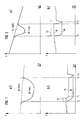
- Fig. 1a shows the course of the rotational speeds of the rear wheels HL and HR of a four-wheel vehicle in a conventional representation.
- the right rear wheel HR may run on a relatively smoother surface than the left rear wheel HL.
- FIG. 1b shows the associated course of the brake pressures on the low and high rear wheels over the same time scale. This requires a relatively low coefficient of friction on the road, i.e. there is a relatively low pressure level (see FIG. 2).
- the measured slip or the deceleration of the low wheel HR indicates that a pressure reduction is necessary because the wheel becomes unstable.
- the high wheel is still stable at this point. 1, the high wheel is never unstable.
- the measured values relating to the low wheel indicate that a constant pressure is required.
- the high rear wheel is from the time t ab for a predetermined period of time ⁇ t of e.g. Maintained at constant brake pressure for 40 ms. Then the pressure on the high wheel is lowered until the time t 1. From the time t 1, the pressure on the high rear wheel is kept constant, but at a higher level than the brake pressure of the low rear wheel HR. This results in a relatively high braking effect with the high rear wheel. There is a smaller difference in braking torque compared to a conventional "select-low" control.
- the computer of the ABS system determines that the low wheel HR starts again to run in a stable area of the coefficient of friction / slip curve. Therefore, at the time t2 the brake pressure on the high rear wheel HL is reduced so that it has the same level at time t3 as the brake pressure on the low rear wheel. At time t3, the brake pressures on both wheels HL and HR are built up together.
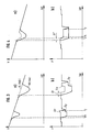
- Fig. 2 shows the case of a relatively high coefficient of friction (rough road) and correspondingly high pressure levels and short pressure reduction times.
- the time scale in Fig. 2 is considerably extended compared to Fig. 1, approximately by a factor of 4 to 5, compare the time periods ⁇ t, which are the same in both cases, namely e.g. 40 ms.
- the low wheel recovers relatively quickly, namely before the 40 ms has elapsed, which is why the adjustment of the brake pressure on the high wheel does not occur after the specified time period ⁇ t (40 ms).
- the brake pressure on the high rear wheel HL at time t2 that is short (a few ms) before the start of the pressure increase on the low rear wheel (t3) is lowered and the two brake pressures HL and HR are brought to the same level as shown in FIG. 2b.
- FIGS. 1 and 2 show that in the latter case a relatively large pressure difference between the high and the low rear wheel is maintained over a relatively long period of time, which has the advantage that the high rear wheel has a relatively good braking effect is achieved. Due to the assumed good coefficients of friction, good lateral guidance for the vehicle is still retained. A dangerous yaw moment around the vertical axis of the vehicle cannot occur due to the weakened difference in braking torque on the wheels of the rear axle.
- Fig. 3 shows conditions that also require a high coefficient of friction.
- the low wheel accelerates more than a predetermined threshold value. This indicates that the low wheel is on a good road. To shorten the braking distance, the braking pressure can therefore be increased without the risk of a loss of stability.
- Fig. 3b Both the high rear wheel and the low rear wheel receive a short pressure pulse ⁇ p which, as a function of the measured re-acceleration, turns out to be even stronger in the second control cycle according to FIG. 3 than in the first control cycle.
- the predetermined time period ⁇ t (40 ms) is reached, i.e. there is a reduction in the brake pressure on the high wheel after the period of time .DELTA.t.
- Fig. 4 assumes that both wheels become unstable due to the slip and rotation deceleration values measured separately for them, so that independent pressure reduction requirements are made for both wheels.
- the pressure reduction request has the highest priority on both wheels.
- the time period ⁇ t ' is less than or equal to the predetermined time period ⁇ t.
- the measurement of the rotational behavior of the high wheel indicates that it becomes unstable and therefore requires an independent pressure reduction.
- the measurements show that a constant brake pressure is required, as shown in Fig. 4b.
- time t2 there is an adjustment of the brake pressures, as described above.
- Fig. 5 shows the situation with a relatively long pressure reduction corresponding to a relatively low coefficient of friction.
- the brake pressures of the high and low rear wheels are very similar here, for example in comparison with FIG. 2, so that the differences in the braking torques on the left and right of the vehicle are relatively small. This takes into account the relatively smooth road surface and prevents torque around the vertical axis of the vehicle.
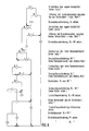
- FIG. 6 shows a flowchart for software implementation of an ABS algorithm described above.
Landscapes
- Engineering & Computer Science (AREA)
- Transportation (AREA)
- Mechanical Engineering (AREA)
- Regulating Braking Force (AREA)
- Hydraulic Control Valves For Brake Systems (AREA)
Applications Claiming Priority (2)
| Application Number | Priority Date | Filing Date | Title |
|---|---|---|---|
| DE3943308A DE3943308A1 (de) | 1989-12-29 | 1989-12-29 | Verfahren zum steuern der bremsdrucke in den bremsen der hinterraeder eines zweispurigen fahrzeuges |
| DE3943308 | 1989-12-29 |
Publications (3)
| Publication Number | Publication Date |
|---|---|
| EP0435114A2 true EP0435114A2 (fr) | 1991-07-03 |
| EP0435114A3 EP0435114A3 (en) | 1993-01-13 |
| EP0435114B1 EP0435114B1 (fr) | 1995-05-31 |
Family
ID=6396614
Family Applications (1)
| Application Number | Title | Priority Date | Filing Date |
|---|---|---|---|
| EP90124249A Expired - Lifetime EP0435114B1 (fr) | 1989-12-29 | 1990-12-14 | Procédé pour commander la pression de freinage dans les freins des roues arrières d'un véhicule à deux ornières |
Country Status (6)
| Country | Link |
|---|---|
| EP (1) | EP0435114B1 (fr) |
| JP (1) | JPH03292248A (fr) |
| KR (1) | KR0179999B1 (fr) |
| BR (1) | BR9006617A (fr) |
| DE (2) | DE3943308A1 (fr) |
| ES (1) | ES2073499T3 (fr) |
Cited By (5)
| Publication number | Priority date | Publication date | Assignee | Title |
|---|---|---|---|---|
| EP0665147A3 (fr) * | 1994-02-01 | 1996-05-15 | Lucas Ind Plc | Logique pour la réduction de pression asynchrone des roues arrières dans des systèmes de contrÔle d'un ABS. |
| WO1996015924A1 (fr) * | 1994-11-23 | 1996-05-30 | Itt Automotive Europe Gmbh | Circuiterie pour systeme de freinage a regulation antiblocage |
| DE19609852A1 (de) * | 1995-03-13 | 1996-09-19 | Toyota Motor Co Ltd | Bremssystem |
| WO1999031950A3 (fr) * | 1997-12-20 | 1999-11-11 | Continental Teves Ag & Co Ohg | Procede et dispositif pour accroitre la stabilite d'un vehicule roulant |
| EP0786388A3 (fr) * | 1996-01-29 | 2000-03-15 | Toyota Jidosha Kabushiki Kaisha | Appareil de commande anti-blocage |
Families Citing this family (1)
| Publication number | Priority date | Publication date | Assignee | Title |
|---|---|---|---|---|
| JP5208810B2 (ja) | 2009-02-27 | 2013-06-12 | 株式会社東芝 | 情報処理装置、情報処理方法、情報処理プログラム、およびネットワーク会議システム |
Family Cites Families (3)
| Publication number | Priority date | Publication date | Assignee | Title |
|---|---|---|---|---|
| DE2851107C2 (de) * | 1978-11-25 | 1990-03-08 | Wabco Westinghouse Fahrzeugbremsen GmbH, 3000 Hannover | Schaltungsanordnung zur Verbesserung der Fahrstabilität von mit blockiergeschützten Bremsanlagen ausgerüsteten Fahrzeugen |
| DE3209369A1 (de) * | 1982-03-15 | 1983-09-22 | Robert Bosch Gmbh, 7000 Stuttgart | Antiblockierregelsystem |
| DE3815732C2 (de) * | 1988-05-07 | 1999-05-12 | Teves Gmbh Alfred | Schaltungsanordnung für eine Bremsanlage mit Blockierschutzregelung |
-
1989
- 1989-12-29 DE DE3943308A patent/DE3943308A1/de not_active Withdrawn
-
1990
- 1990-12-14 DE DE59009181T patent/DE59009181D1/de not_active Expired - Lifetime
- 1990-12-14 ES ES90124249T patent/ES2073499T3/es not_active Expired - Lifetime
- 1990-12-14 EP EP90124249A patent/EP0435114B1/fr not_active Expired - Lifetime
- 1990-12-22 KR KR1019900021413A patent/KR0179999B1/ko not_active Expired - Fee Related
- 1990-12-27 BR BR909006617A patent/BR9006617A/pt not_active IP Right Cessation
- 1990-12-27 JP JP2408022A patent/JPH03292248A/ja active Pending
Cited By (9)
| Publication number | Priority date | Publication date | Assignee | Title |
|---|---|---|---|---|
| EP0665147A3 (fr) * | 1994-02-01 | 1996-05-15 | Lucas Ind Plc | Logique pour la réduction de pression asynchrone des roues arrières dans des systèmes de contrÔle d'un ABS. |
| US5613742A (en) * | 1994-02-01 | 1997-03-25 | Lucas Industries Public Limited Company | Asynchronous rear dump logic in ABS control systems |
| WO1996015924A1 (fr) * | 1994-11-23 | 1996-05-30 | Itt Automotive Europe Gmbh | Circuiterie pour systeme de freinage a regulation antiblocage |
| US5865514A (en) * | 1994-11-23 | 1999-02-02 | Itt Manufacturing Enterprises Inc. | Circuit arrangement for a braking system with anti-lock control system |
| DE19609852A1 (de) * | 1995-03-13 | 1996-09-19 | Toyota Motor Co Ltd | Bremssystem |
| US5788342A (en) * | 1995-03-13 | 1998-08-04 | Toyota Jidosha Kabushiki Kaisha | Braking system having pump connected to two brake cylinders through respective delivery ports that are disconnected from each other in a portion of delivery stroke of the pump |
| DE19609852C2 (de) * | 1995-03-13 | 2001-08-09 | Toyota Motor Co Ltd | Bremssystem |
| EP0786388A3 (fr) * | 1996-01-29 | 2000-03-15 | Toyota Jidosha Kabushiki Kaisha | Appareil de commande anti-blocage |
| WO1999031950A3 (fr) * | 1997-12-20 | 1999-11-11 | Continental Teves Ag & Co Ohg | Procede et dispositif pour accroitre la stabilite d'un vehicule roulant |
Also Published As
| Publication number | Publication date |
|---|---|
| JPH03292248A (ja) | 1991-12-24 |
| KR0179999B1 (ko) | 1999-03-20 |
| ES2073499T3 (es) | 1995-08-16 |
| DE3943308A1 (de) | 1991-07-04 |
| DE59009181D1 (de) | 1995-07-06 |
| KR910011560A (ko) | 1991-08-07 |
| EP0435114A3 (en) | 1993-01-13 |
| BR9006617A (pt) | 1991-10-01 |
| EP0435114B1 (fr) | 1995-05-31 |
Similar Documents
| Publication | Publication Date | Title |
|---|---|---|
| EP1334017B1 (fr) | Procede pour reguler la stabilite de conduite d'un vehicule | |
| DE3933653B4 (de) | Radschlupfregelsystem | |
| EP0418264B1 (fr) | Procede pour ameliorer la maitrise d'un vehicule freine | |
| DE4111515C2 (de) | Antiblockiersystem für ein Fahrzeug | |
| DE19638430A1 (de) | System und Verfahren zur Bremskraftsteuerung | |
| DE19636920A1 (de) | System und Verfahren zur Bremskraftsteuerung | |
| EP0807562A2 (fr) | Procédé pour affaiblir le moment de giration dans un système antiblocage | |
| DE10149190A1 (de) | Vorrichtung und Verfahren zur Wankregelung für ein Fahrzeug | |
| DE19545001B4 (de) | Verfahren zur Giermoment-Abschwächung bei einem Antiblockiersystem | |
| DE19628486A1 (de) | Brems-Steuer/Regel-System für ein Fahrzeug | |
| EP1379419B1 (fr) | Procede programmable electroniquement permettant d'ameliorer le comportement du reglage d'un systeme de reglage de freinage antiblocage | |
| EP1545950B1 (fr) | Procede pour ameliorer la tenue de route d'un vehicule en cas de conduite avec freinage partiel | |
| DE10119907B4 (de) | Verfahren zur Regelung der Fahrstabilität | |
| EP0435114B1 (fr) | Procédé pour commander la pression de freinage dans les freins des roues arrières d'un véhicule à deux ornières | |
| EP0451240B1 (fr) | Procede de reglage de la pression de freinage d'un systeme de freinage de vehicules a anti-bloqueur | |
| EP0330064A2 (fr) | Procédé de régulation de la pression de freinage | |
| DE3835095A1 (de) | Verfahren zum regeln des bremsdruckes in einer blockiergeschuetzten fahrzeugbremsanlage | |
| DE19944333B4 (de) | Vorrichtung zur Regelung eines Giermoments | |
| DE4323275A1 (de) | Antriebsschlupfregelung | |
| DE3934307C2 (de) | Verfahren zum Steuern des Bremsdruckes in einer blockiergeschützten Bremsanlage | |
| DE102010039823A1 (de) | Verfahren und Vorrichtung zur Antriebsschlupfregelung eines Einspurfahrzeugs | |
| DE102008046259A1 (de) | Verfahren und Vorrichtung zum Bestimmen einer Fahrstabilität eines Fahrzeugs beim Bremsen und Verfahren und Vorrichtung zum Einstellen eines Bremsdrucks für ein Fahrzeug | |
| EP0448670B1 (fr) | Procede de regulation de la pression des freins dans un systeme de freinage avec anti-derapeur automatique pour un vehicule a essieu | |
| EP1023211B1 (fr) | Procede et dispositif pour ameliorer la stabilite d'un vehicule et la regulation de la pression de freinage | |
| DE19542295B4 (de) | Bremssystem für ein Fahrzeug |
Legal Events
| Date | Code | Title | Description |
|---|---|---|---|
| PUAI | Public reference made under article 153(3) epc to a published international application that has entered the european phase |
Free format text: ORIGINAL CODE: 0009012 |
|
| AK | Designated contracting states |
Kind code of ref document: A2 Designated state(s): DE ES FR GB IT |
|
| PUAL | Search report despatched |
Free format text: ORIGINAL CODE: 0009013 |
|
| AK | Designated contracting states |
Kind code of ref document: A3 Designated state(s): DE ES FR GB IT |
|
| 17P | Request for examination filed |
Effective date: 19930208 |
|
| 17Q | First examination report despatched |
Effective date: 19940211 |
|
| GRAA | (expected) grant |
Free format text: ORIGINAL CODE: 0009210 |
|
| AK | Designated contracting states |
Kind code of ref document: B1 Designated state(s): DE ES FR GB IT |
|
| GBT | Gb: translation of ep patent filed (gb section 77(6)(a)/1977) |
Effective date: 19950605 |
|
| REF | Corresponds to: |
Ref document number: 59009181 Country of ref document: DE Date of ref document: 19950706 |
|
| REG | Reference to a national code |
Ref country code: ES Ref legal event code: FG2A Ref document number: 2073499 Country of ref document: ES Kind code of ref document: T3 |
|
| ITF | It: translation for a ep patent filed | ||
| ET | Fr: translation filed | ||
| PLAV | Examination of admissibility of opposition |
Free format text: ORIGINAL CODE: EPIDOS OPEX |
|
| PLBI | Opposition filed |
Free format text: ORIGINAL CODE: 0009260 |
|
| PLAV | Examination of admissibility of opposition |
Free format text: ORIGINAL CODE: EPIDOS OPEX |
|
| PLBF | Reply of patent proprietor to notice(s) of opposition |
Free format text: ORIGINAL CODE: EPIDOS OBSO |
|
| 26 | Opposition filed |
Opponent name: ITT AUTOMOTIVE EUROPE GMBH Effective date: 19960223 |
|
| PLBF | Reply of patent proprietor to notice(s) of opposition |
Free format text: ORIGINAL CODE: EPIDOS OBSO |
|
| PLBO | Opposition rejected |
Free format text: ORIGINAL CODE: EPIDOS REJO |
|
| PLBN | Opposition rejected |
Free format text: ORIGINAL CODE: 0009273 |
|
| STAA | Information on the status of an ep patent application or granted ep patent |
Free format text: STATUS: OPPOSITION REJECTED |
|
| 27O | Opposition rejected |
Effective date: 19970505 |
|
| REG | Reference to a national code |
Ref country code: GB Ref legal event code: IF02 |
|
| REG | Reference to a national code |
Ref country code: GB Ref legal event code: 732E |
|
| REG | Reference to a national code |
Ref country code: GB Ref legal event code: 732E |
|
| PGFP | Annual fee paid to national office [announced via postgrant information from national office to epo] |
Ref country code: ES Payment date: 20081219 Year of fee payment: 19 |
|
| PGFP | Annual fee paid to national office [announced via postgrant information from national office to epo] |
Ref country code: IT Payment date: 20081212 Year of fee payment: 19 |
|
| PGFP | Annual fee paid to national office [announced via postgrant information from national office to epo] |
Ref country code: FR Payment date: 20081205 Year of fee payment: 19 |
|
| PGFP | Annual fee paid to national office [announced via postgrant information from national office to epo] |
Ref country code: GB Payment date: 20081110 Year of fee payment: 19 |
|
| PGFP | Annual fee paid to national office [announced via postgrant information from national office to epo] |
Ref country code: DE Payment date: 20091222 Year of fee payment: 20 |
|
| GBPC | Gb: european patent ceased through non-payment of renewal fee |
Effective date: 20091214 |
|
| REG | Reference to a national code |
Ref country code: FR Ref legal event code: ST Effective date: 20100831 |
|
| PG25 | Lapsed in a contracting state [announced via postgrant information from national office to epo] |
Ref country code: FR Free format text: LAPSE BECAUSE OF NON-PAYMENT OF DUE FEES Effective date: 20091231 |
|
| PG25 | Lapsed in a contracting state [announced via postgrant information from national office to epo] |
Ref country code: GB Free format text: LAPSE BECAUSE OF NON-PAYMENT OF DUE FEES Effective date: 20091214 |
|
| PG25 | Lapsed in a contracting state [announced via postgrant information from national office to epo] |
Ref country code: IT Free format text: LAPSE BECAUSE OF NON-PAYMENT OF DUE FEES Effective date: 20091214 |
|
| REG | Reference to a national code |
Ref country code: ES Ref legal event code: FD2A Effective date: 20111116 |
|
| PG25 | Lapsed in a contracting state [announced via postgrant information from national office to epo] |
Ref country code: ES Free format text: LAPSE BECAUSE OF NON-PAYMENT OF DUE FEES Effective date: 20091215 |
|
| PG25 | Lapsed in a contracting state [announced via postgrant information from national office to epo] |
Ref country code: DE Free format text: LAPSE BECAUSE OF EXPIRATION OF PROTECTION Effective date: 20101214 |