EP1023211B1 - Procede et dispositif pour ameliorer la stabilite d'un vehicule et la regulation de la pression de freinage - Google Patents
Procede et dispositif pour ameliorer la stabilite d'un vehicule et la regulation de la pression de freinage Download PDFInfo
- Publication number
- EP1023211B1 EP1023211B1 EP98955464A EP98955464A EP1023211B1 EP 1023211 B1 EP1023211 B1 EP 1023211B1 EP 98955464 A EP98955464 A EP 98955464A EP 98955464 A EP98955464 A EP 98955464A EP 1023211 B1 EP1023211 B1 EP 1023211B1
- Authority
- EP
- European Patent Office
- Prior art keywords
- wheel
- hand side
- side wheel
- vehicle
- slip
- Prior art date
- Legal status (The legal status is an assumption and is not a legal conclusion. Google has not performed a legal analysis and makes no representation as to the accuracy of the status listed.)
- Expired - Lifetime
Links
- 238000000034 method Methods 0.000 title claims description 25
- 230000001133 acceleration Effects 0.000 claims description 17
- 230000009467 reduction Effects 0.000 claims description 17
- 230000010355 oscillation Effects 0.000 claims 3
- 238000011156 evaluation Methods 0.000 claims 2
- 238000001514 detection method Methods 0.000 description 10
- 230000003247 decreasing effect Effects 0.000 description 4
- 238000010586 diagram Methods 0.000 description 4
- 230000008859 change Effects 0.000 description 3
- 238000006243 chemical reaction Methods 0.000 description 3
- 230000001419 dependent effect Effects 0.000 description 3
- 230000000087 stabilizing effect Effects 0.000 description 3
- 241000792859 Enema Species 0.000 description 2
- 230000000694 effects Effects 0.000 description 2
- 239000007920 enema Substances 0.000 description 2
- 229940079360 enema for constipation Drugs 0.000 description 2
- 230000008569 process Effects 0.000 description 2
- 238000012935 Averaging Methods 0.000 description 1
- 230000004048 modification Effects 0.000 description 1
- 238000012986 modification Methods 0.000 description 1
- 230000004043 responsiveness Effects 0.000 description 1
- 238000005096 rolling process Methods 0.000 description 1
- 239000013589 supplement Substances 0.000 description 1
- 230000007704 transition Effects 0.000 description 1
Images



Classifications
-
- B—PERFORMING OPERATIONS; TRANSPORTING
- B60—VEHICLES IN GENERAL
- B60T—VEHICLE BRAKE CONTROL SYSTEMS OR PARTS THEREOF; BRAKE CONTROL SYSTEMS OR PARTS THEREOF, IN GENERAL; ARRANGEMENT OF BRAKING ELEMENTS ON VEHICLES IN GENERAL; PORTABLE DEVICES FOR PREVENTING UNWANTED MOVEMENT OF VEHICLES; VEHICLE MODIFICATIONS TO FACILITATE COOLING OF BRAKES
- B60T8/00—Arrangements for adjusting wheel-braking force to meet varying vehicular or ground-surface conditions, e.g. limiting or varying distribution of braking force
- B60T8/17—Using electrical or electronic regulation means to control braking
- B60T8/1755—Brake regulation specially adapted to control the stability of the vehicle, e.g. taking into account yaw rate or transverse acceleration in a curve
-
- B—PERFORMING OPERATIONS; TRANSPORTING
- B60—VEHICLES IN GENERAL
- B60T—VEHICLE BRAKE CONTROL SYSTEMS OR PARTS THEREOF; BRAKE CONTROL SYSTEMS OR PARTS THEREOF, IN GENERAL; ARRANGEMENT OF BRAKING ELEMENTS ON VEHICLES IN GENERAL; PORTABLE DEVICES FOR PREVENTING UNWANTED MOVEMENT OF VEHICLES; VEHICLE MODIFICATIONS TO FACILITATE COOLING OF BRAKES
- B60T2201/00—Particular use of vehicle brake systems; Special systems using also the brakes; Special software modules within the brake system controller
- B60T2201/16—Curve braking control, e.g. turn control within ABS control algorithm
Definitions
- the invention relates to a method and a device for improving the stability of a vehicle and for controlling the brake pressure.
- the described methods and apparatus relate in particular to the area of partial braking, that is to say when all wheels of a vehicle are braked with the same brake pressure or when the ABS does not yet engage.
- Partially braked maneuvers represent a dynamic driving problem in the stability limit range that is not adequately controlled by conventional anti-lock braking systems.
- Especially vehicles with short wheelbase tend in such braking situations to sudden oversteer, which is difficult to predict by the driver and can not be corrected in real driving situations.
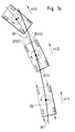
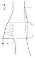
- the problem of oversteering during partial braking is explained with reference to FIG. 1a.
- a vehicle 100 moves in the figure from bottom to top along the curve 101 (solid line).
- ABS is a wheel-individual control, which has relatively insensitive threshold values with respect to the respective wheel slip. ABS would intervene in Fig. 1a only in the upper position, when the vehicle has already built a considerable float angle. Then it can not be stabilized by ABS anymore.
- the object of the invention is to provide a method and a device for detecting an unstable braking and for controlling the brake pressure in the partial braking area, with which an unstable braking detected or can be prevented as far as possible.
- the running behavior of a single wheel is not only selectively checked. Rather, the running behavior of a left-hand wheel is compared with the running behavior of a right-hand wheel, and / or it is the time course of the running behavior of a preferably inner wheel curve over a longer time considered and evaluated. Based on these criteria, an unstable braking can be detected, so that appropriate countermeasures can be initiated.
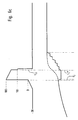
- FIG. 1b shows an exemplary partial braking situation in the cornering range at which the ABS intervention begins too late.
- the graph above shows in curve 103 the vehicle speed and in curve 104 any wheel speed.
- the lower diagram shows with curve 105 the wheel brake pressure and with the dashed curve 106 in comparison to the brake pressure in the tandem master cylinder. If the wheel slip values are sufficient to activate the ABS, the vehicle has already reached a very large slip angle. The then on all wheels incipient pressure reduction causes no stabilizing counter-torque, since in general no braking force difference arises on an axis.
- the ABS reduces the wheel brake pressures to near 0 bar, typically at time T3 of the illustrated example, without the wheels being able to accelerate again. This is only possible again when the vehicle has rotated more than 90 ° around the vertical axis and then hurls (from time T4). The ABS is thus unable to prevent the vehicle being turned in towards the inside of the curve.
- the wheel-specific anti-lock control is not useful in this case, since the slip is due to the high Radschräglaufwinkel, but not due to overbraking. Consequently, the attempt to counteract the slip inlet of the wheel by pressure reduction, does not make sense, can even be dangerous, since the vehicle then after a rotation by more than 90 ° suddenly braked in the running direction of the wheels can spin (time T4).
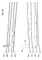
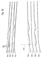
- FIGS. 2a-c show different typical time courses for on the one hand wheel speeds and on the other hand brake pressures at the individual wheels.
- the dashed curve 200 respectively indicates the vehicle reference speed as determined, for example, based on wheel sensors or other devices.
- the curves 201a, b, c and d denote wheel speeds of the individual wheels of the vehicle, 201a relates to the front left wheel 201b front right, 201c rear right and 201d rear left.
- the individual wheel speeds are related to the vehicle reference speed (one value has been adapted in its dimensioning to the other (conversion between web speed and angular speed)).
- the curves 202a-d indicate braking pressures at the individual wheels, the allocation between indices a-d and the wheels of the vehicle such as already mentioned above.
- the solid lines are the actual prevailing wheel brake pressures, while the dashed lines shows the pressure in the master cylinder of the brake system.
- FIG. 2a shows a typical wheel speed pattern for a partially braked oversteer situation in a front wheel drive vehicle.
- the inboard wheels (a and d) assume slowly increasing slip values when the brake is applied, while the outer wheels (b and c) initially run stably.
- the outer wheels show virtually no vibrations, but rather the speed profiles are smooth, i. the wheel acceleration is in a narrow band for vehicle acceleration.
- the less loaded wheel usually shows certain vibration reactions and sometimes also deep slip enemas.
- In front-wheel drive vehicles this is the rear wheel ( Figure 2a, curve 201d), while in rear-wheel drive vehicles the front wheel is affected (Figure 2b, curve 201a).
- Fig. 2c shows a lane change maneuver in which steering is first to the left and then to the right. As a result, first some slip builds up on the left wheels (a and d) and then on the right wheels (b and c), which then disappears again.
- curves 202a-d in FIGS. 2a-c show the inventively modified wheel brake pressures for the respective wheels. Their course will be explained later.
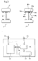
- FIG. 3 several embodiments of the invention are shown in combination schematically.
- a vehicle is shown, with right front and left rear.
- 301a is the left front wheel
- 302a a corresponding wheel sensor with a signal line 305a
- 303a symbolizes the wheel brake
- 304a a hydraulic control part
- 306a a signal feed line for controlling the hydraulic 304a. mutatis mutandis, the same arrangements can be found on the other wheels (right front with the indices "b", right behind with the indices "c” and left behind with the indices "d”).
- Axle 310 is the front axle
- axle 311 is the rear axle.
- 313 is a schematic diagram of an unstable braking detection device according to the present invention
- 314 is a train of output signals
- 315 is a schematic diagram of a brake pressure control device according to the present invention.
- This generates suitable signals for controlling the wheel brakes or modifies already generated signals in a suitable manner.
- it may be embedded in a larger device 317.
- This device 317 may include a more comprehensive brake control 318, which may also include the ABS.
- the recognition device 313 receives a string of input signals 312, which may include, inter alia, the signals 305a-d of the wheel sensors 302a-d as well as further signals, for example vehicle reference speed v Ref .
- the signal train 314 may also contain a plurality of signals, for example a signal that allows an association between left-hand side / right-hand side and turn-curve outside, a signal indicative of the presence of unstable braking, timing signals, etc.
- the output signal train 316 may include signal lines relating to the input signals 306a-d of the respective valves 304a-d of the respective wheel brakes 303a-d.
- the recognition device 313 recognizes an unstable braking of a two-lane vehicle, either by means of a comparator the running behavior of at least one Left-hand wheel is compared with that of a right-hand wheel, and / or by the time course of at least one wheel is considered and evaluated.
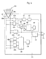
- the recognition device 313 receives via the signal train 312, for example, the signals 305a-d of the wheel sensors 302a-d, wherein by way of example only the signals 305c, d of the rear axle are shown.
- 402 is a detecting means for detecting the inside of the turn of the vehicle. For example, it can compare the wheel speeds of non-driven wheels of an axle (ie the rear axle in front-wheel drive). The faster wheel will be on the outside, the slower on the inside. This is also true in view of the fact that slip enemas are expected.
- the outside wheels are more heavily loaded so that they still run without slippage when the less heavily loaded, inside wheels already slip exhibit and thus are slower.
- a determination device 403a, b, 408a, b is provided which determines the slip and / or the acceleration of the considered wheels.
- 403a, b are slip-averaging devices which receive a wheel signal on the one hand and the vehicle reference speed 401 on the other hand. From this, the slip of a wheel under consideration can be determined (where slip is the difference between wheel speed and vehicle speed, so that the slip in turn is the dimension of a speed Has).
- Reference numerals 408a-408c designate acceleration judging means which detect wheel accelerations and vehicle acceleration, respectively, by receiving as inputs the respective wheel signals 305c, d and the vehicle speed 401, respectively, and deriving therefrom the respective accelerations. They can each contain differentiators.
- Vibrations of a wheel speed can indicate unstable conditions, see for example curve 201a in FIG. 2b.
- Such vibrations can be detected, for example, by looking at wheel accelerations and checking that these accelerations are within a certain band around the vehicle acceleration. Preferably, not punctual values are used for the decision, but processes over a longer period are considered.
- Typical vibration frequencies of the slip are around 10 Hz, so that observation periods can be in the range between 10 and 300 ms, preferably between 100 and 200 ms. If significant deviations of a wheel acceleration from a vehicle acceleration are detected during such a time window, eg based on one or more outbreaks from a range of values around the vehicle acceleration, an unstable braking can be detected.
- 411 is a third comparison device that may be provided in addition to or instead of the first comparison device 409. It compares directly slip values of wheels with each other, wherein the slip of a left-hand wheel with the slip of a right-hand wheel, preferably on the same axis, compared with each other. If these values differ by a certain amount, and in particular if the slip of the inside wheel is significantly higher than the slip of the outside wheel, then an unstable braking can be concluded. Here, too, the timing of unit 412 can be considered.
- the above options may be provided individually or in combination with each other.
- the actual decision as to whether an unstable braking is present is made by the detection device 413. It receives the individual signals and links them, optionally in accordance with further input signals, to an output signal that provides information about whether an unstable signal is present Braking is present.
- an intervention in the brake system can take place in such a way that a counteracting torque is generated counteracting torque.
- This can be done by producing a stronger braking force outside the curve than inside the curve. This can be caused by the brake pressure is increased outside the curve or curves inside lowered. The latter may be preferable since, in a critical braking situation, it may be useful overall to reduce braking forces rather than increasing them. Accordingly, then the inner side of the brake pressure would be lower. As a result, a lower braking force is created on the inside of the curve than on the outside of the curve. This results in a torque acting out of the curve, which counteracts the moment of inertia of the braked vehicle acting inwards and thus has a total stabilizing effect.
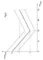
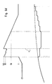
- FIG. 5 shows by way of example how slip threshold values can be selected by the determination device 406 as a function of the vehicle reference speed.
- different curves such as curves 501, 502 or 503 can be selected. The curves show that at the minimum (ie at about 100 km / h) a slip of between about 1 and 6% and preferably about 3% is allowed.
- FIGS. 6a-d respectively show braking pressures with the lower curve, as they are described by a method according to the invention Control of the brake pressure on the detection of a critical braking situation were changed (solid line) compared to the value as it would have been produced without change by the other brake control / control (for example, 318) (dashed line 602).
- Line 603 shows the count of a counter used to control timing for detection and pressure control.
- period 604 the critical braking is detected. If this is detected (t 2 ), the brake pressure is lowered on a curve-inside wheel. The pressure then drops in the period 605 (t 2 -t 3 ) and is kept constant for a specific or determinable period of time (period 606, t 3 -t 4 ). Thereafter (period 607, t 4 - t 5 ) it is gradually rebuilt until it has taken the value without the change (time t 5 ).
- the time duration of holding the pressure at the lowered value can also be determined by the count 603 of the above-mentioned counter. Shown is an embodiment in which at the beginning of the lowering of the counter is set to 100 and then counted down, at the value 50 is started with the gradual reconstruction of the brake pressure.
- the detection period is set from -20 to 0 by incrementing the counter.
- the slip behavior of the wheel can be checked. In particular, it can be checked whether the slip is decreasing, which can be expected a priori after a brake pressure reduction. When the slip does not decrease, the duration of the pressure reduction can be extended. This is shown in Fig. 6b. There it is assumed that no or only insufficient slippage could be determined (in each case at the times t 6 , t 7 , t 8 , t 9 and t 10 ). At these times, it is decided, respectively, that the duration of the lowering of the brake pressure is to be changed. In the embodiment shown, this can be done, for example, by raising the counter reading a little at a time, so that the time until it counts down to the threshold value 50 is longer. Finally, at time t 4 ', the threshold value is reached and phase 607 of the pressure build-up begins as in FIG. 6 a.
- Fig. 6c a case is shown in which it is determined at time t 11 that the slip has gone back so clearly that can be started immediately with the new brake pressure build-up.
- the phase of decreasing the brake pressure may then be shortened or aborted, for example by setting the count to the threshold requested for the repressurization decision or to reset it completely (as requested). Then the renewed step-by-step pressure build-up starts earlier, in FIG. 6c this is the case from time t 4 ".
- Fig. 6d shows the case in which checking the wheel slip during the phase of decreasing the brake pressure keeps the slip from decreasing or even increasing as desired (interrogation at time t 12 ). Then a new pressure reduction can take place, whereby the brake pressure is reduced again. This is followed by the same options as described with reference to FIGS. 6a-c.
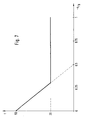
- Fig. 7 shows a diagram that indirectly the pressure reduction depending on the vehicle reference delay. Immediately reproduced the driving time for the exhaust valve of the wheel, wherein the drive time is proportional to the pressure reduction in the first approximation. In addition, a lower vehicle reference deceleration leads to the introduction of a lower pressure in the wheel brakes, so that a pressure reduction by a certain amount due to the volume-pressure characteristic of the brake and the characteristic of the switching valves requires a longer valve control.
- the detection of critical braking described above does not require additional sensors. It evaluates the (for example pulsating) signals of the wheel sensors 302a-d. This is advantageous because then neither new sensors nor new cabling costs are to be accepted.
- the detection can be made only by supplements in the control part.
- the described detection of a critical braking is not mandatory in the described embodiment. Other embodiments, for example via their own sensors, are possible.
- the critical wheel signals may be expected on the inner wheel (s), which are less loaded. Accordingly, each of the mentioned wheels are usefully monitored to detect the critical braking.
- the above-mentioned detection of a critical braking or the subsequent brake pressure control relates to the range of partial braking, ie the area in which the ABS does not yet engage and preferably the braking forces (without modification) are the same on all wheels. Should the slip behavior of a single wheel be such that the ABS would intervene, the method according to the invention can be aborted, the anti-lock braking system then alone controls the brake pressures of the individual wheels.
- an electronic braking force distribution control is generally used today, which distributes the braking force between the front axle and the rear axle in the partial braking region, so that the braking pressures are not the same on all wheels even in the partial braking range.
- the electronic brake force distribution normally occurs before the method according to the invention comes into effect and is already stabilizing with its mostly quite large pressure reductions.
- the electronic brake force distribution between the front and rear axles alone is not sufficient to stabilize the vehicle in a really critical curve situation. Therefore, it makes sense in front-wheel drive vehicles both components, namely the electronic brake force distribution between the front and rear axles and the brake pressure control method according to the invention (ultimately braking force distribution between inside and outside curves) to activate.
- the brake pressure control described may use components of the anti-lock brake system, such as signal inputs or signal outputs.
Landscapes
- Engineering & Computer Science (AREA)
- Transportation (AREA)
- Mechanical Engineering (AREA)
- Regulating Braking Force (AREA)
Claims (26)
- Procédé pour améliorer la stabilité d'un véhicule à deux voies pendant une conduite en courbe à freinage partiel dans laquelle aucune régulation ABS n'intervient encore, avec pour étape la détermination du comportement au roulement d'au moins une roue côté gauche et d'une roue côté droit,
caractérisé par une appréciation de la situation de freinage lors du freinage partiel, par comparaison du comportement au roulement d'au moins une roue côté gauche à celui d'une roue côté droit et/ou par exploitation de l'allure temporelle d'au moins une roue côté gauche et d'une roue côté droit, et reconnaissance d'un freinage critique dans le domaine du freinage partiel à l'aide du résultat de la comparaison et/ou du résultat de l'exploitation, en ce qu'à partir des différences des vitesses des roues et de la vitesse longitudinale déterminée du véhicule, on conclut à des tendances à la rotation vers l'intérieur du véhicule et celles-ci sont classées comme critiques pour le domaine du freinage partiel. - Procédé selon la revendication 1, caractérisé en ce que comme comportement du roulement d'une roue son patinage ou son accélération est déterminée.
- Procédé selon la revendication 2, caractérisé en ce qu'au moins une valeur de seuil du patinage est comparée au patinage effectif d'au moins une roue.
- Procédé selon la revendication 2 ou 3, caractérisé en ce que la variation dans le temps du patinage est examinée quant aux oscillations et un freinage critique est reconnu en cas d'oscillations déterminées.
- Procédé selon la revendication 3, caractérisé en ce que la valeur de seuil est déterminée en fonction de la vitesse du véhicule.
- Procédé selon l'une des revendications précédentes, caractérisé en ce que le côté intérieur de la courbe est déterminé à l'aide des vitesses d'une roue côté gauche non motrice et d'une roue côté droit non motrice.
- Procédé selon la revendication 6, caractérisé en ce que le côté intérieur de la courbe est déterminé à l'aide des vitesses des roues sur l'essieu arrière.
- Procédé selon l'une des revendications précédentes, caractérisé en ce que la vitesse de roue d'au moins une roue côté gauche est comparée à la vitesse de roue d'au moins une roue côté droit, et un freinage critique est reconnu lorsque les vitesses des roues s'écartent l'une de l'autre, conformément à un modèle déterminé, sur une durée déterminée ou à déterminer.
- Procédé selon l'une des revendications précédentes, caractérisé en ce qu'il est commencé dans le domaine du freinage partiel et n'est pas exécuté dans le domaine du freinage total.
- Procédé de commande de la pression de freinage d'au moins une roue lors d'un freinage critique d'un véhicule à deux voies pendant la conduite en courbe, caractérisé par les étapes de la reconnaissance d'un freinage critique du véhicule pendant la conduite en courbe, avec un procédé selon l'une des revendications précédentes,
détermination d'une roue côté intérieur à la courbe à l'aide des vitesses d'une roue côté gauche non directrice et d'une roue côté droit non motrice, et abaissement de la pression de freinage sur l'une ou les deux roues côté intérieur à la courbe à la suite de la reconnaissance. - Procédé selon la revendication 10, caractérisé en ce que la valeur de l'abaissement est choisie en fonction du ralentissement du véhicule.
- Procédé selon l'une des revendications 10 ou 11 précédentes, caractérisé en ce que la pression abaissée est maintenue pendant un temps déterminé ou qui peut être déterminé puis est à nouveau relevée.
- Procédé selon la revendication 12, caractérisé en ce que la pression est encore abaissée si après un abaissement le patinage ne sous-dépasse pas une valeur déterminée ou à déterminer.
- Dispositif pour améliorer la stabilité d'un véhicule à deux voies pendant une conduite en courbe à freinage partiel, au cours de laquelle une régulation ABS n'a pas encore lieu, comportant un dispositif de détermination (403a, b, 408a, b) pour déterminer le comportement au roulement d'au moins une roue côté gauche et d'une roue côté droit (301a-d),
caractérisé par un premier dispositif de comparaison (409-412) pour la comparaison du comportement au roulement d'au moins une roue côté gauche à une roue côté droit et/ou un dispositif d'exploitation (404-407) pour l'exploitation de l'allure temporelle d'au moins une roue côté gauche et d'une roue côté droit, et un dispositif de reconnaissance (413) pour reconnaître un freinage critique à l'aide de la sortie du dispositif de comparaison et/ou de la sortie du dispositif d'exploitation, en ce qu'à partir de la différence des vitesses des roues et de la vitesse longitudinale déterminée du véhicule, on conclut à des tendances à la rotation vers l'intérieur du véhicule et celles-ci sont classées comme critiques pour le domaine du freinage partiel. - Dispositif selon la revendication 14, caractérisé en ce que le dispositif de détermination (403a, b, 408a, b) détermine le patinage et/ou l'accélération des roues considérées.
- Dispositif selon la revendication 15, caractérisé en ce que le dispositif d'exploitation (404-407) comporte un deuxième dispositif de comparaison (405) qui compare une valeur de seuil du patinage au patinage effectif d'au moins une roue.
- Dispositif selon la revendication 15 ou 16,
caractérisé en ce que le dispositif d'exploitation (404-407) examine la variation dans le temps du patinage quant aux oscillations. - Dispositif selon la revendication 16, caractérisé par un dispositif de détermination (406) qui détermine la valeur de seuil en fonction de la vitesse du véhicule.
- Dispositif selon l'une des revendications 14 à 18 précédentes, caractérisé par un dispositif de détermination (402) qui détermine le côté intérieur de la courbe à l'aide d'un signal d'une roue côté gauche non motrice et d'une roue côté droit non motrice.
- Dispositif selon la revendication 19, caractérisé en ce que le dispositif de détermination considère les vitesses des roues sur l'essieu arrière.
- Dispositif selon l'une des revendications 14 à 20 précédentes, caractérisé par un troisième dispositif de comparaison (411) qui compare la vitesse de roue d'au moins une roue côté gauche à la vitesse de roue d'au moins une roue côté droit, et le dispositif de reconnaissance reconnaissant un freinage critique lorsque les vitesses des roues s'écartent l'une de l'autre conformément à un modèle déterminé pendant une durée déterminée ou à déterminer.
- Dispositif selon l'une des revendications 14 à 21 précédentes, caractérisé en ce qu'il agit dans le domaine du freinage partiel et est désactivé dans le domaine du freinage complet.
- Dispositif de commande de la pression de freinage d'au moins une roue lors d'un freinage critique d'un véhicule à deux voies pendant la conduite en courbe,
caractérisé par un dispositif (313) pour la reconnaissance d'un freinage critique du véhicule pendant la conduite en courbe, selon l'une des revendications 14 à 22 précédentes, un dispositif (402) pour déterminer une roue côté intérieur à la courbe à l'aide de signaux d'une roue côté gauche non motrice et d'une roue côté droit non motrice, ainsi que par un dispositif de variations (315) pour abaisser la pression de freinage d'une roue côté intérieur à la courbe à la suite de la reconnaissance. - Dispositif selon la revendication 23, caractérisé en ce que le dispositif de variations choisit la valeur de l'abaissement en fonction du ralentissement du véhicule.
- Dispositif selon l'une des revendications 14 à 245 précédentes, caractérisé en ce que le dispositif de variations maintient la pression abaissée pendant un temps déterminé ou à déterminer puis la relève à nouveau.
- Dispositif selon la revendication 25, caractérisé en ce que le dispositif de variation continue d'abaisser la pression si après un abaissement le patinage ne sous-dépasse pas une valeur déterminée ou à déterminer.
Applications Claiming Priority (7)
| Application Number | Priority Date | Filing Date | Title |
|---|---|---|---|
| DE19745912 | 1997-10-17 | ||
| DE19745912 | 1997-10-17 | ||
| DE19755781 | 1997-12-16 | ||
| DE19755781 | 1997-12-16 | ||
| DE19817285 | 1998-04-18 | ||
| DE19817285A DE19817285A1 (de) | 1997-10-17 | 1998-04-18 | Verfahren und Vorrichtung zum Erkennen einer instabilen Bremsung sowie zum Steuern des Bremsdrucks |
| PCT/EP1998/006563 WO1999020506A1 (fr) | 1997-10-17 | 1998-10-16 | Procede et dispositif pour la reconnaissance d'un freinage instable et pour la regulation de la pression de freinage |
Publications (2)
| Publication Number | Publication Date |
|---|---|
| EP1023211A1 EP1023211A1 (fr) | 2000-08-02 |
| EP1023211B1 true EP1023211B1 (fr) | 2006-10-11 |
Family
ID=27217837
Family Applications (1)
| Application Number | Title | Priority Date | Filing Date |
|---|---|---|---|
| EP98955464A Expired - Lifetime EP1023211B1 (fr) | 1997-10-17 | 1998-10-16 | Procede et dispositif pour ameliorer la stabilite d'un vehicule et la regulation de la pression de freinage |
Country Status (5)
| Country | Link |
|---|---|
| US (1) | US6435627B1 (fr) |
| EP (1) | EP1023211B1 (fr) |
| JP (1) | JP2001520143A (fr) |
| DE (1) | DE59813764D1 (fr) |
| WO (1) | WO1999020506A1 (fr) |
Families Citing this family (5)
| Publication number | Priority date | Publication date | Assignee | Title |
|---|---|---|---|---|
| US8500219B2 (en) * | 2008-02-22 | 2013-08-06 | Continental Teves Ag & Co. Ohg | Method and device for stabilizing a vehicle |
| US8303049B2 (en) * | 2010-03-12 | 2012-11-06 | GM Global Technology Operations LLC | Method for operating a vehicle brake system |
| US8645040B2 (en) * | 2010-05-06 | 2014-02-04 | GM Global Technology Operations LLC | Method for operating a vehicle brake system |
| US8874346B2 (en) * | 2012-11-15 | 2014-10-28 | Caterpillar Inc. | System with blended anti-lock and stability control |
| CN118665497B (zh) * | 2024-05-20 | 2026-03-06 | 一汽解放汽车有限公司 | 驾驶行为的评估方法、装置、设备和介质 |
Family Cites Families (22)
| Publication number | Priority date | Publication date | Assignee | Title |
|---|---|---|---|---|
| DE3429156C2 (de) * | 1984-08-08 | 1994-06-23 | Teves Gmbh Alfred | Schaltungsanordnung zur Überwachung und Steuerung einer blockiergeschützten Bremsanlage |
| JPS62240287A (ja) * | 1986-04-11 | 1987-10-21 | 株式会社日立製作所 | マンコンベアの移動手摺駆動装置 |
| JP2510238B2 (ja) * | 1988-04-07 | 1996-06-26 | 日産自動車株式会社 | 車両のトラクションコントロ―ル装置 |
| US5230550A (en) * | 1989-12-29 | 1993-07-27 | Lucas Industries Public Limited Company | Method of controlling the brake pressure in the rear wheel brakes of a double-track vehicle |
| DE4123234C1 (fr) | 1991-07-13 | 1992-08-27 | Mercedes-Benz Aktiengesellschaft, 7000 Stuttgart, De | |
| JPH0522565A (ja) * | 1991-07-15 | 1993-01-29 | Ricoh Co Ltd | 通信装置 |
| JP3723228B2 (ja) * | 1992-02-06 | 2005-12-07 | アイシン精機株式会社 | アンチスキッド制御装置 |
| DE4327491C2 (de) | 1993-08-16 | 1996-08-29 | Daimler Benz Ag | Verfahren zum Abgleichen der Raddrehzahlen für ein Kraftfahrzeug |
| DE4418772C2 (de) | 1994-05-28 | 2000-08-24 | Daimler Chrysler Ag | Verfahren zur Regelung des Bremsdrucks in Abhängigkeit der Abweichung des Istschlupfes von Rädern zu einem Sollschlupf |
| US5774821A (en) * | 1994-11-25 | 1998-06-30 | Itt Automotive Europe Gmbh | System for driving stability control |
| JPH08164836A (ja) * | 1994-12-15 | 1996-06-25 | Nisshinbo Ind Inc | アンチスキッド制御方法 |
| DE19503076A1 (de) | 1995-02-01 | 1996-08-08 | Teves Gmbh Alfred | Verfahren zum Betreiben einer blockiergeschützten Kraftfahrzeugbremsanlage |
| DE19510104C1 (de) | 1995-03-20 | 1996-08-14 | Bayerische Motoren Werke Ag | ABS- und/oder ASC-Regelsystem für Kraftfahrzeuge |
| DE19522634A1 (de) * | 1995-06-22 | 1997-01-02 | Teves Gmbh Alfred | Verfahren zur Kurvenfahrterkennung für ein Blockierschutzregelungssystem |
| DE19522632A1 (de) * | 1995-06-22 | 1997-01-02 | Teves Gmbh Alfred | Verfahren zur Verbesserung des Regelverhaltens eines Blockierschutzregelungssystems |
| JPH0986365A (ja) * | 1995-09-21 | 1997-03-31 | Fuji Heavy Ind Ltd | 制動力制御装置 |
| US5927830A (en) * | 1995-11-30 | 1999-07-27 | Aisin Seiki Kabushiki Kaisha | Vehicle motion control system for immediately terminating braking control when the vehicle enters onto a stepped or rough road |
| DE19602994A1 (de) | 1996-01-27 | 1997-07-31 | Teves Gmbh Alfred | Verfahren zur Bestimmung von Größen, die das Fahrverhalten eines Fahrzeugs beschreiben |
| JPH09207745A (ja) * | 1996-01-30 | 1997-08-12 | Nissan Motor Co Ltd | アンチスキッド制御装置 |
| DE19628973A1 (de) * | 1996-07-18 | 1998-01-22 | Teves Gmbh Alfred | Verfahren zur Verbesserung des Regelverhaltens eines Antiblockiersystems |
| JPH1178842A (ja) * | 1997-09-09 | 1999-03-23 | Unisia Jecs Corp | ブレーキ制御装置 |
| US6056371A (en) * | 1998-08-24 | 2000-05-02 | General Motors Corporation | Feed-forward active brake control |
-
1998
- 1998-10-16 US US09/529,209 patent/US6435627B1/en not_active Expired - Lifetime
- 1998-10-16 JP JP2000516862A patent/JP2001520143A/ja not_active Withdrawn
- 1998-10-16 DE DE59813764T patent/DE59813764D1/de not_active Expired - Lifetime
- 1998-10-16 WO PCT/EP1998/006563 patent/WO1999020506A1/fr not_active Ceased
- 1998-10-16 EP EP98955464A patent/EP1023211B1/fr not_active Expired - Lifetime
Also Published As
| Publication number | Publication date |
|---|---|
| JP2001520143A (ja) | 2001-10-30 |
| EP1023211A1 (fr) | 2000-08-02 |
| WO1999020506A1 (fr) | 1999-04-29 |
| US6435627B1 (en) | 2002-08-20 |
| DE59813764D1 (de) | 2006-11-23 |
Similar Documents
| Publication | Publication Date | Title |
|---|---|---|
| EP1334017B1 (fr) | Procede pour reguler la stabilite de conduite d'un vehicule | |
| DE3933653B4 (de) | Radschlupfregelsystem | |
| DE19624198B4 (de) | Bremskraftregelvorrichtung für ein Kraftfahrzeug | |
| EP1040035B1 (fr) | Procede et dispositif pour limiter l'acceleration transversale d'un vehicule en marche | |
| DE10356510A1 (de) | Fahrdynamikregelung mit vorgezogenem Druckaufbau am zu regelnden Rad | |
| EP1926643B1 (fr) | Procede pour detecter une trajectoire de circulation non homogene | |
| EP1131235B1 (fr) | Procede et dispositif de stabilisation d'un vehicule equipe d'un systeme de freinage a controle de glissement | |
| EP1040034B1 (fr) | Procede et dispositif pour ameliorer la tenue de route d'un vehicule lors de la negociation d'un virage avec freinage | |
| EP1545950B1 (fr) | Procede pour ameliorer la tenue de route d'un vehicule en cas de conduite avec freinage partiel | |
| EP4013651B1 (fr) | Méthode de commande d'un véhicule ayant des efors de freinage diffèrents selon le coté gauche et droit, système de freinage associé et véhicule | |
| DE10119907B4 (de) | Verfahren zur Regelung der Fahrstabilität | |
| EP0363959B1 (fr) | Procédé de régulation de la pression de freinage dans une installation de freinage de véhicule à antiblocage | |
| EP1156952B1 (fr) | Dispositif et procede de regulation du glissement de roues apres detection d'un derapage | |
| DE102008027093B4 (de) | Technik zum Betreiben einer Bremsanlage in einer μ-Split-Situation | |
| EP1023211B1 (fr) | Procede et dispositif pour ameliorer la stabilite d'un vehicule et la regulation de la pression de freinage | |
| WO2020057854A1 (fr) | Procédé de commande d'un véhicule pendant un freinage mu-split, système de commande et véhicule | |
| DE19830190A1 (de) | Verfahren und Vorrichtung zur Begrenzung der Querbeschleunigung eines fahrenden Fahrzeugs | |
| DE19817285A1 (de) | Verfahren und Vorrichtung zum Erkennen einer instabilen Bremsung sowie zum Steuern des Bremsdrucks | |
| EP1419083B1 (fr) | Systeme de direction de vehicule automobile comportant un regulateur du taux de lacet | |
| EP0435114B1 (fr) | Procédé pour commander la pression de freinage dans les freins des roues arrières d'un véhicule à deux ornières | |
| DE19820107A1 (de) | Verfahren und Vorrichtung zur Verbesserung der Fahreigenschaft eines Fahrzeugs bei gebremster Kurvenfahrt | |
| DE10207378A1 (de) | Verfahren und Vorrichtung zur Verbesserung des Bremsverhaltens | |
| DE10316253B4 (de) | Verfahren zum Modifizieren einer Fahrstabilitätsregelung eines Fahrzeugs | |
| EP0999962A1 (fr) | Procede et dispositif permettant de detecter une situation de freinage dans une courbe et comportant un ecart mu | |
| EP1101675A2 (fr) | Procédé et dispositif d'ajustement de l'effet de freinage dans un véhicule |
Legal Events
| Date | Code | Title | Description |
|---|---|---|---|
| PUAI | Public reference made under article 153(3) epc to a published international application that has entered the european phase |
Free format text: ORIGINAL CODE: 0009012 |
|
| 17P | Request for examination filed |
Effective date: 20000517 |
|
| AK | Designated contracting states |
Kind code of ref document: A1 Designated state(s): DE FR GB |
|
| 17Q | First examination report despatched |
Effective date: 20021220 |
|
| RTI1 | Title (correction) |
Free format text: METHOD AND DEVICE FOR IMPROVING THE STABILITY OF A VEHICLE AND CONTROLLING BRAKING PRESSURE |
|
| GRAP | Despatch of communication of intention to grant a patent |
Free format text: ORIGINAL CODE: EPIDOSNIGR1 |
|
| GRAS | Grant fee paid |
Free format text: ORIGINAL CODE: EPIDOSNIGR3 |
|
| GRAA | (expected) grant |
Free format text: ORIGINAL CODE: 0009210 |
|
| AK | Designated contracting states |
Kind code of ref document: B1 Designated state(s): DE FR GB |
|
| REG | Reference to a national code |
Ref country code: GB Ref legal event code: FG4D |
|
| REF | Corresponds to: |
Ref document number: 59813764 Country of ref document: DE Date of ref document: 20061123 Kind code of ref document: P |
|
| ET | Fr: translation filed | ||
| GBV | Gb: ep patent (uk) treated as always having been void in accordance with gb section 77(7)/1977 [no translation filed] |
Effective date: 20061011 |
|
| PLBE | No opposition filed within time limit |
Free format text: ORIGINAL CODE: 0009261 |
|
| STAA | Information on the status of an ep patent application or granted ep patent |
Free format text: STATUS: NO OPPOSITION FILED WITHIN TIME LIMIT |
|
| 26N | No opposition filed |
Effective date: 20070712 |
|
| PG25 | Lapsed in a contracting state [announced via postgrant information from national office to epo] |
Ref country code: GB Free format text: LAPSE BECAUSE OF FAILURE TO SUBMIT A TRANSLATION OF THE DESCRIPTION OR TO PAY THE FEE WITHIN THE PRESCRIBED TIME-LIMIT Effective date: 20061011 |
|
| REG | Reference to a national code |
Ref country code: FR Ref legal event code: PLFP Year of fee payment: 18 |
|
| REG | Reference to a national code |
Ref country code: FR Ref legal event code: PLFP Year of fee payment: 19 |
|
| PGFP | Annual fee paid to national office [announced via postgrant information from national office to epo] |
Ref country code: DE Payment date: 20161031 Year of fee payment: 19 Ref country code: FR Payment date: 20161020 Year of fee payment: 19 |
|
| REG | Reference to a national code |
Ref country code: DE Ref legal event code: R119 Ref document number: 59813764 Country of ref document: DE |
|
| REG | Reference to a national code |
Ref country code: FR Ref legal event code: ST Effective date: 20180629 |
|
| PG25 | Lapsed in a contracting state [announced via postgrant information from national office to epo] |
Ref country code: DE Free format text: LAPSE BECAUSE OF NON-PAYMENT OF DUE FEES Effective date: 20180501 |
|
| PG25 | Lapsed in a contracting state [announced via postgrant information from national office to epo] |
Ref country code: FR Free format text: LAPSE BECAUSE OF NON-PAYMENT OF DUE FEES Effective date: 20171031 |