EP0435139A2 - Contrôleur programmable pour éxecuter des programmes en langage SFC - Google Patents
Contrôleur programmable pour éxecuter des programmes en langage SFC Download PDFInfo
- Publication number
- EP0435139A2 EP0435139A2 EP90124607A EP90124607A EP0435139A2 EP 0435139 A2 EP0435139 A2 EP 0435139A2 EP 90124607 A EP90124607 A EP 90124607A EP 90124607 A EP90124607 A EP 90124607A EP 0435139 A2 EP0435139 A2 EP 0435139A2
- Authority
- EP
- European Patent Office
- Prior art keywords
- program
- storing
- transition
- active
- steps
- Prior art date
- Legal status (The legal status is an assumption and is not a legal conclusion. Google has not performed a legal analysis and makes no representation as to the accuracy of the status listed.)
- Granted
Links
Images


Classifications
-
- G—PHYSICS
- G05—CONTROLLING; REGULATING
- G05B—CONTROL OR REGULATING SYSTEMS IN GENERAL; FUNCTIONAL ELEMENTS OF SUCH SYSTEMS; MONITORING OR TESTING ARRANGEMENTS FOR SUCH SYSTEMS OR ELEMENTS
- G05B19/00—Program-control systems
- G05B19/02—Program-control systems electric
- G05B19/04—Program control other than numerical control, i.e. in sequence controllers or logic controllers
- G05B19/05—Programmable logic controllers, e.g. simulating logic interconnections of signals according to ladder diagrams or function charts
- G05B19/058—Safety, monitoring
Definitions
- the present invention relates to a programmable controller which executes programs written in a sequential function chart (SFC) language.
- SFC sequential function chart
- PC programmable controller
- Fig. 7 is a block diagram illustrating the configuration of PCs known in the prior art.
- a CPU 1 for running a sequence program is connected by a common bus 6 to several components including a ROM 2 for storing a microprogram 2B as an operating system (OS) which controls the CPU 1, an input/output interface 3 for transferring data to and from an object to be controlled (not illustrated), a program storing RAM 5 for storing a sequence program 5D, and a RAM 4 for use during execution of the sequence program, including an internal relay module 4B that operates to provide programmed logical contacts.
- OS operating system
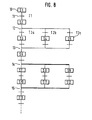
- Fig. 8 gives an example of an SFC program organized in a ladder chart format.
- the SFC program is a representation of a control sequence in a flow format, comprising a combination of steps (designated by "S") indicating certain definite operations and “transitions” (designated by “T”) indicating transition conditions for the execution of the steps.
- a step being executed is referred to as an "active step”, and is made inactive and passes execution to a subsequent step when its incidental transition condition is established.
- numeral 10 indicates a step (S1) and numeral 11 a "transition” (T1).
- a transition from the step being executed to the next step to be executed is made in several ways.
- Transition 11 is a "serial transition" which causes an active step (S1) to transit to the only step (S2) to which it connects.
- a “selective branch” 12 causes an active step (S2) to be followed by any of a plurality of branch destinations, depending on which transition condition T2a-T2c is established first.
- a “selective link” 13 indicates a link of the selective branch 12, to an active step (S6).
- a “parallel branch” 14 executes a plurality of steps (S7 to S9) concurrently and executes following steps S10 to S12 when their transition conditions are established.
- a "parallel link” 15 indicates the link of paths from a plurality of steps being executed concurrently by the parallel branch 14. When the execution of all the parallel-branched paths is complete, the parallel link 15 is completed and the next step (S13) is then executed.
- Fig. 9 is a sequence ladder diagram which illustrates an example of a sequence program developed from the SFC program shown in Fig. 8.
- the numerals 20 and 20a identify internal relay contacts which are logical contacts. These contacts are switched ON/OFF in accordance with the activation/deactivation of the corresponding steps in the SFC program.
- operation output instructions 21 and 21a for steps executed when the corresponding steps in the SFC program become active, i.e. when the internal relay contacts 20,20a are switched ON.
- 22 and 22a to 22c are transition condition instructions for "transitions" established when the corresponding steps become active.
- Elements 23 and 23a to 23c are "reset” instructions executed when the corresponding transition conditions are established, for switching OFF the internal relay contact 20 or 20a correspondingly. Finally, elements 24 and 24a to 24c are “set” instructions executed when the corresponding transition conditions are established for switching ON internal relay contacts corresponding to the next active steps.
- Fig. 10 is a flowchart illustrating a procedure for converting the SFC program written by a program writing device (not illustrated) into a sequence program and loading the sequence program into the PC.
- the program writing device is started up at step 200. Whether the SFC program is to be newly written or to be corrected is judged at step 210. If a new program is to be written, an SFC program like that shown in Fig. 8 is prepared at step 202. If the SFC program is to be corrected, it is corrected and rewritten at step 203. In either case, at step 204, the resultant SFC program is then converted into a sequence program (represented by the ladder diagram of Fig. 9) by a known technique. At step 205, the sequence program is loaded into the program storing RAM 5 of the PC, shown in Fig. 7, and the sequence is terminated at step 206.
- the CPU 1 runs the sequence program stored in the program storing RAM 5 according to the microprogram 2B placed in the ROM 2.
- the execution/non-execution of each step is processed on the basis of the execution condition (i.e. ON>OFF) of the corresponding internal relays in module 4B, and in accordance with the activation/deactivation of each step.
- the step S1 in Fig. 8 is active, the subsequent operation output instruction 21 in Fig. 9 is executed because the internal relay contact 20 is ON.
- the transition condition 22, corresponding to the transition condition of the transition T1 in Fig. 8, is also judged. If the result of the instruction is established, an instruction for deactivating step S1, i.e. the reset instruction 23 for switching OFF the internal relay contact 20, is executed. Also, the set instruction for activating the subsequent step S2, i.e. the instruction 24 for switching ON the internal relay contact 20A (M2), is executed.
- the sequence program is run repeatedly by the CPU 1.
- the SFC program is followed, Specifically, performance of the active step takes place and condition judgement of a transition incidental to that active step and a change of the active step at the establishment of its condition are performed. This performance corresponds directly to the ON/OFF, or set/reset, of the internal relay(s) related to each step.
- sequence program 5D must be changed, in whole or in part, data stored in the program storing RAM 5 must be changed but this is difficult to do. Moreover, once converted into sequence form, it is difficult to enter partial corrections to the program. Therefore, the whole SFC program must be rewritten, reconverted to a sequence program and reloaded into the PC. This results in several problems for the prior art PC. First, the program conversion process takes a relatively long time. Second, if the program has been changed to correct an error, the effect of the change cannot be determined until the rewritten program is converted, reloaded and run. Further, if it is desired to execute only one of the paths in the parallel branch of the SFC program, modification of the SFC program must be accomplished during debugging of the sequence program. This is difficult to do in the prior art and results in significant inconvenience for the program user.
- a further problem with the prior art is that, during operation of the program, the particular step that was active at a given time can not be immediately identified for purposes of trouble shooting or modification. Thus, the entire program had to be searched in order to identify what step was active.
- a programmable controller for executing a program which comprises a plurality of steps that follow a path, each step of which comprises object and transition portions for implementation by a respective run program and which are identified by a label
- the controller being characterised in that it comprises memory for storing the run programs at respective addresses, an active step table for storing at least one label indicating an active step in the programs, a step execution address table for storing memory addresses of the run programs in correspondence with the label or labels, an active step execution means for reading from the step execution address table the memory address of the run program corresponding to the label stored in the active step table and for reading and executing the run program corresponding to the active step, a step transition management table for storing management information for a transition from a currently active step to the next active step, and an active step transition means for storing a label for the next active step in the active step table in accordance with the transition management information stored in the step transition management table.
- the PC comprises in a second embodiment, in addition to the elements of the PC of the first embodiment, a step transition management table changing unit for changing the management information concerning the transition to the corresponding step stored in the step transition management table according to the path designation specifying a change of the next active step to which transit will be made.
- the active step executing unit checks the step I.D. number of the active step stored in the active step table, reads the execution address of the active step from the step execution address storing table in accordance with the step I.D. number, and reads and executes the active step stored at the read execution address in the memory. Also, the active step transition unit stores the step I.D. number of the next active step to transmit into the active step table according to the management information on transition stored in the step transition management table when the transition condition of the active step is established.
- the step transition management table changing unit changes the management information for transition to the corresponding step stored in the step transition management table according to the path designation which indicates a change of the next active step to which transit will be made.
- an I/O interface is operative to input information to specify steps and transition conditions of a program and to identify active steps and transition conditions stored in memory, as the program is run, thereby facilitating program debugging operations.
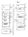
- Fig. 1 is a block diagram illustrating a configuration of the PC in the first and second embodiments of the present invention.
- CPU 1 is connected by bus 6 to several components, including a variety of storage elements and an I/O interface structure 3 that connects to the controlled object, an input device, a display and like peripherals.
- One storage element, RAM 4 is a conventional "OS working RAM” that stores an operating system used for operating the CPU 1.
- the RAM 4 also contains an active step table 4A for storing an I.D. number assigned to steps in the SFC program that will become active during the program execution.
- One or more run programs 5A are stored in a program storing RAM 5.
- Each of the run programs 5A comprises an "operation output” portion for executing a sequence instruction for an SFC step and for providing its operation output, and a "transition condition” portion for determining a transition condition to the next active step.
- the operation output portion and transition condition portion for each SFC step includes head addresses that correspond to an I.D. number uniquely assigned to each step.
- the operation output portion and the transition condition portion are equivalent to the operation output portion 21 and the transition condition portion 22 in the sequence program arrangement of the prior art, respectively, and comprises an instruction step string composed of a plurality of instruction steps.
- RAM 5 also contains a step execution address storing table 5B that is operative to correlate between the step I.D.
- a step transition management table 5C in RAM 5 is used for storing step transition destination management information for each SFC step so that from one active step the process can correctly proceed to the next active step.
- the table 5C stores for step S6 the number of transition destination steps (i.e., three) and the transition destination step I.D. numbers (i.e., S7, S8, S9).
- ROM 2 is also connected to bus 6 and contains a microprogram 2A.
- the CPU 1 By running the microprogram 2A, the CPU 1 conducts several functions. Using an active step execution routine 7, the CPU reads the step number of the active step form the active step table 4A, reads the head addresses of the operation output portion and the transition condition portion of the run program corresponding to the step number of the active step from table 5B, reads the run program 5A from the program storing RAM 5 in accordance with the head addresses so obtained , and executes the operation output portion and the transition condition portion.
- the CPU 1 also runs active step transition routine 8 for reading the step transition destination management information from the step transition management table 5C and for storing in active step table 4A the step I.D. number of the next active step to which transit will be made. Finally, the CPU 1 runs a step transition management table changing routine 9 for changing the transition destination management information, such as the number of SFC step transition destinations and the transition destination step I.D. numbers, stored in the step transition management table 5C, on the basis
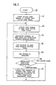
- Fig. 2 is a flowchart illustrating a procedure for running the SFC program in the PC.
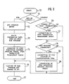
- Figure 3 is a flowchart illustrating a procedure for writing, correcting and downloading to the PC the SFC program, using a peripheral device (not illustrated) as a programming device.
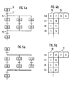
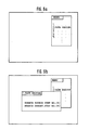
- Figs. 4a and 4b are diagrams showing an example of a parallel branch having three branched paths in the SFC program and an example of the step transition management table 5C corresponding to the parallel branch in the SFC program, respectively.
- Figs. 5a and 5b are diagrams showing an example where only the centre path of the three branched paths shown in Figs. 4a,4b is executed and an example of the step transition management table 5C corresponding to such SFC program, respectively.
- the number 50 indicates the quantity or number of transition destination step storage locations.
- the number 51 indicates transition destination step number storage locations that store the transition destination step I.D. numbers.
- Both the portions 50 and 51 are configured as one or more bytes in memory so that the number of transition destination steps and the transition destination step I.D. numbers may be stored as numerical values.
- step 100 When execution is started at step 100, initialization is made at step 101, and the I.D. number of the first step to be an active step is automatically stored in the active step table 4A in the RAM 4. Then, the CPU 1 runs the microprogram 2A to cause the active step execution routine 7 to read the step I.D. number for the active step from the active step table 4A at step 102. Next, the execution routine 7 reads the head addresses of the run program corresponding to the read step I.D. number from among the run programs 5A at step 103. The read addresses comprise the head address of the operation output portion and that of the transition condition portion of the run program.
- the CPU 1 will read the corresponding run program 5A from the RAM 5 at step 104, and execute the operation output portion and the transition condition portion of the read run program 5A at step 105. Then, at step 106, a judgement is made as to whether or not the transition condition of the active step has been established. This judgement is made on the basis of the execution of the transition condition portion. If the condition has not been established, the procedure returns to step 102. If the condition has been established, the active step transition routine 8 checks the step transition management table 5C at step 107, reads the number identifying the quantity of transition destination steps which are to be the next active steps, and the transition destination step I.D. numbers, corrects the active step table 4A on the basis of the read step I.D. number(s) and returns to step 102.
- the active step transition routine 8 judges the next active step will now be described with reference to Figs. 2, 4a and 4b.
- the active step transition routine finds that there are three transition destinations in the following manner. First, it checks the portion 50 of the step transition management table 5C shown in Fig. 4b, which corresponds to the SFC step (S6) and identifies the number (3) of transition destination steps. Second, on the basis of the identified number of steps, it reads the first three step I.D. numbers from the transition destination step number storing portion 51 of the table 5C. In step 107, the active step table 4A is corrected to store "3" as the number of transition destination steps, and to store the transition destination step numbers (7 to 9).
- An END processing portion of the SFC program is supplied as one of the run programs.
- the step transition management table 5C is written so that when END processing is complete, the active step returns to the first step of the SFC program. As a result, the SFC program is continually repeated.
- Fig. 7 Since the prior art shown in Fig. 7 runs the SFC program after conversion thereof into an ordinary sequence program, it executes not only active steps but also inactive steps. However, since the embodiment of the present invention only executes run programs corresponding to active steps, it provides a highly responsive PC which significantly reduces the length of time required for one scan of the SFC program as compared to the prior art. This feature is particularly important when debugging a program under varying operating conditions.
- a peripheral device (not illustrated) starts execution of the procedure at step 110.
- the procedure judges whether an incoming SFC program write request is for writing a new program or correcting an existing program. If the request is to write a new program, the SFC program is written at step 112, and the written SFC program is automatically converted into run programs 5A in correspondence with the SFC steps executable by the PC at step 113. Thereafter, the step execution address storing table 5B and the step transition management table 5C are automatically created at step 114. Finally, the run programs 5A, the step execution address storing table 5B and the step transition management table 5C are downloaded to the program storing RAM 5 of the PC at step 115.
- step 116 If the SFC program write request is for correction of a program, whether the correction is concerned with a step transition destination sequence change or not is judged at step 116. If the answer is NO, the procedure jumps to step 118. If the answer is YES, the corresponding area of the step transition management table 5C is corrected at step 117. Then, at step 118, a judgement is made as to whether or not a correction has been made to the content of the run program itself. If the answer is NO, the procedure jumps to the step 115. If YES, the SFC program area of the corresponding SFC step is corrected and automatically converted into a run program at step 119. The corresponding areas of the step execution address storing table 5B and the step transition management table 5C are automatically created or corrected at step 120. Finally, the run program 5A, the step execution address storing table 5B and the step transition management table 5C are downloaded to the program storing RAM 5 of the PC at step 115, and the sequence is completed at step 121.
- the correction or modification of a program may only require a change of the run program(s) 5A corresponding to the relevant step(s).
- steps can be reorganized or deleted simply by changing the content of one or more of the tables, for example by changing the pointers to the run programs for each of the respective SFC steps.
- the correction can be finished in a relatively short time.
- step transition management table 5C is changed as shown in Fig. 5b (explained below) by the step transition management table changing routine 9.
- step S6 connects only to step S8, S11 and S13 in sequence. There is no connection between steps S7-S10 or steps S9-S12 in the program. These steps remain as run programs in area 5A for subsequent connection/selection as desired.
- the number of transition destinations stored in the transition destination storing portion 50 is 3.
- the transition destination step numbers stored in the transition destination step number storing portion 51 are 7, 8, 9 in the step transition management table 5C shown in Fig. 4b.
- the desired specified path is set up by writing into area 50 the number 1, representing the number of transition destination steps.
- the number 8 is moved to the first location of area 51, representing the sole transition destination step number.
- Step numbers 7 and 9 remain in area 51 as data identifying available but not specified paths. These paths are can be identified for later access, if desired, by changing the table again. For example, when it is desired to cancel the specified path, it is only necessary to return the number of transition destination steps to the original number 3.
- step S2 when it is desired to change the priority of transitions judged for a selective branch, that change can be made by changing the transition destination step numbers to be judged by the step transition management table 5C, using routine 9.
- step S2 when step S2 is the active step, the sequence of transition condition judgement is made in the order of transitions T2a, T2b, T2c at the selective branch 12 to activate the SFC step following the established transition. This may easily be changed to the order T2b, T2a, T2c, for example. This is accomplished by changing the sequence of the judged transitions in the step transition management table 5C to T2b, T2a, T2c by means of the step transition management table changing routine 9.
- Figs. 6a and 6b illustrate an example of controlling the path designation operation procedure from a peripheral device by way of a screen display.
- the branch source step 6 and the branch destination step number 8 are specified to allow only the step S8 to be executed from among the three parallel branches from step S6, as shown in Fig. 5a.
- the path could be reconfigured from a serial to a parallel path.
- the first embodiment provides a PC which improves the execution speed of SFC programs and corrects SFC programs efficiently, owing to the active step execution routine, the active step transition routine and the split-conversion of the SFC program into run programs corresponding to the SFC steps.
- the run programs are executed using the active step table, the step execution address storing table and the step transition management table.
- the second embodiment provides a PC which easily permits execution of a selected specified path or paths from among plural paths branched in parallel via use of a step transition management table changing routine that changes the management information on the transition of the corresponding step stored in the step transition management table.
- the present invention is particularly useful for debugging and testing of programs since active steps can be identified, set and changed quickly.
- Program paths can be readily reorganized and a visual display of the operation and available selections can be easily presented to an operator for efficient diagnosis, analysis and modification.
Landscapes
- Physics & Mathematics (AREA)
- General Physics & Mathematics (AREA)
- Engineering & Computer Science (AREA)
- Automation & Control Theory (AREA)
- Programmable Controllers (AREA)
Applications Claiming Priority (2)
| Application Number | Priority Date | Filing Date | Title |
|---|---|---|---|
| JP337934/89 | 1989-12-26 | ||
| JP1337934A JP2526686B2 (ja) | 1989-12-26 | 1989-12-26 | プログラマブルコントロ―ラの制御プログラムにおけるプログラム内容の修正方法 |
Publications (3)
| Publication Number | Publication Date |
|---|---|
| EP0435139A2 true EP0435139A2 (fr) | 1991-07-03 |
| EP0435139A3 EP0435139A3 (en) | 1992-07-08 |
| EP0435139B1 EP0435139B1 (fr) | 1996-06-12 |
Family
ID=18313376
Family Applications (1)
| Application Number | Title | Priority Date | Filing Date |
|---|---|---|---|
| EP90124607A Expired - Lifetime EP0435139B1 (fr) | 1989-12-26 | 1990-12-18 | ContrÔleur programmable pour éxecuter des programmes en langage SFC |
Country Status (4)
| Country | Link |
|---|---|
| EP (1) | EP0435139B1 (fr) |
| JP (1) | JP2526686B2 (fr) |
| DE (1) | DE69027413T2 (fr) |
| HK (1) | HK1007011A1 (fr) |
Cited By (5)
| Publication number | Priority date | Publication date | Assignee | Title |
|---|---|---|---|---|
| EP0551132A1 (fr) * | 1992-01-10 | 1993-07-14 | Mitsubishi Denki Kabushiki Kaisha | Système et méthode de commande séquentielle avec correction d'erreur |
| EP0618517A1 (fr) * | 1993-04-02 | 1994-10-05 | Mitsubishi Denki Kabushiki Kaisha | Contrôleur programmable et méthode à exécuter des programmes SFC avec un contrôleur programmable |
| WO1997040431A1 (fr) * | 1996-04-18 | 1997-10-30 | Anton Steinecker Maschinenfabrik Gmbh | Procede pour detecter et documenter des conditions d'avancement non remplies dans des systemes commandes par des programmes pas a pas pour commande par programme enregistre |
| EP0803786A4 (fr) * | 1995-11-09 | 2001-01-10 | Fanuc Ltd | Systeme de commande de l'execution d'un programme sequentiel |
| EP2241949A3 (fr) * | 2009-04-14 | 2011-08-31 | General Electric Company | Procédé d'exécution de diagrammes fonctionnels séquentiels en tant que blocs de fonctions dans un système de contrôle |
Families Citing this family (3)
| Publication number | Priority date | Publication date | Assignee | Title |
|---|---|---|---|---|
| KR101373442B1 (ko) * | 2011-09-16 | 2014-03-13 | 미쓰비시덴키 가부시키가이샤 | 시퀀스 프로그램 작성 장치 |
| JP2016071767A (ja) * | 2014-10-01 | 2016-05-09 | 良成 高橋 | ステージ選択方式plcラダー回路 |
| JP6087478B1 (ja) * | 2016-01-27 | 2017-03-01 | 三菱電機株式会社 | 制御装置及び編集装置 |
Family Cites Families (12)
| Publication number | Priority date | Publication date | Assignee | Title |
|---|---|---|---|---|
| US4189773A (en) * | 1974-07-03 | 1980-02-19 | General Electric Company | On-line memory space allocation |
| US4115853A (en) * | 1976-12-21 | 1978-09-19 | Allen-Bradley Company | Jump structure for a digital control system |
| JPS55135908A (en) * | 1979-04-11 | 1980-10-23 | Hitachi Ltd | Sequence program input device |
| JPS5611502A (en) * | 1979-07-09 | 1981-02-04 | Toyoda Mach Works Ltd | Program correction unit in sequence controller |
| US4488258A (en) * | 1982-09-20 | 1984-12-11 | Allen-Bradley | Programmable controller with control program comments |
| NO171240C (no) * | 1985-04-25 | 1993-02-10 | Bbc Brown Boveri & Cie | Programmeringsanordning for en lagerprogrammerbar styring |
| DE3630959A1 (de) * | 1986-09-11 | 1988-03-24 | Christian Dipl Ing Nitschke | Programmier- und testeinheit fuer speicherprogrammierbare steuerungen |
| JPH01140301A (ja) * | 1987-11-27 | 1989-06-01 | Hitachi Ltd | シーケンス制御方法 |
| JPH07120168B2 (ja) * | 1988-01-29 | 1995-12-20 | ファナック株式会社 | Pc装置の制御方式 |
| US5287548A (en) * | 1988-02-29 | 1994-02-15 | Allen-Bradley Company, Inc. | Programmable controller having a stored program with both machine language instructions and source code data |
| JP2585708B2 (ja) * | 1988-04-28 | 1997-02-26 | 株式会社東芝 | プログラマブルコントローラ |
| JP2618493B2 (ja) * | 1989-09-11 | 1997-06-11 | 株式会社日立製作所 | シーケンス制御装置 |
-
1989
- 1989-12-26 JP JP1337934A patent/JP2526686B2/ja not_active Expired - Lifetime
-
1990
- 1990-12-18 EP EP90124607A patent/EP0435139B1/fr not_active Expired - Lifetime
- 1990-12-18 DE DE1990627413 patent/DE69027413T2/de not_active Expired - Fee Related
-
1998
- 1998-06-23 HK HK98106224A patent/HK1007011A1/en not_active IP Right Cessation
Cited By (10)
| Publication number | Priority date | Publication date | Assignee | Title |
|---|---|---|---|---|
| EP0551132A1 (fr) * | 1992-01-10 | 1993-07-14 | Mitsubishi Denki Kabushiki Kaisha | Système et méthode de commande séquentielle avec correction d'erreur |
| US5485366A (en) * | 1992-01-10 | 1996-01-16 | Mitsubishi Denki Kabushiki Kaisha | Sequence controller including error correction and method therefor |
| EP0618517A1 (fr) * | 1993-04-02 | 1994-10-05 | Mitsubishi Denki Kabushiki Kaisha | Contrôleur programmable et méthode à exécuter des programmes SFC avec un contrôleur programmable |
| EP0753803A1 (fr) * | 1993-04-02 | 1997-01-15 | Mitsubishi Denki Kabushiki Kaisha | ContrÔleur programmable et méthode pour exécuter des programmes SFC avec un contrÔleur programmable |
| US5793947A (en) * | 1993-04-02 | 1998-08-11 | Mitsubishi Denki Kabushiki Kaisha | Programmable controller for synchronously tracing the execution of operation blocks and SFC program execution method using the programmable controller |
| EP0803786A4 (fr) * | 1995-11-09 | 2001-01-10 | Fanuc Ltd | Systeme de commande de l'execution d'un programme sequentiel |
| WO1997040431A1 (fr) * | 1996-04-18 | 1997-10-30 | Anton Steinecker Maschinenfabrik Gmbh | Procede pour detecter et documenter des conditions d'avancement non remplies dans des systemes commandes par des programmes pas a pas pour commande par programme enregistre |
| EP2241949A3 (fr) * | 2009-04-14 | 2011-08-31 | General Electric Company | Procédé d'exécution de diagrammes fonctionnels séquentiels en tant que blocs de fonctions dans un système de contrôle |
| US8903520B2 (en) | 2009-04-14 | 2014-12-02 | General Electric Company | Method for executing sequential function charts as function blocks in a control system |
| CN105404232A (zh) * | 2009-04-14 | 2016-03-16 | 通用电气公司 | 用于在控制系统中将顺序功能图作为功能块执行的方法 |
Also Published As
| Publication number | Publication date |
|---|---|
| DE69027413D1 (de) | 1996-07-18 |
| EP0435139A3 (en) | 1992-07-08 |
| EP0435139B1 (fr) | 1996-06-12 |
| JPH03196303A (ja) | 1991-08-27 |
| HK1007011A1 (en) | 1999-03-26 |
| DE69027413T2 (de) | 1997-02-06 |
| JP2526686B2 (ja) | 1996-08-21 |
Similar Documents
| Publication | Publication Date | Title |
|---|---|---|
| JPH0388046A (ja) | サービス・プロセツサ・テスト装置 | |
| EP0435139A2 (fr) | Contrôleur programmable pour éxecuter des programmes en langage SFC | |
| US5819024A (en) | Fault analysis system | |
| HK1007011B (en) | A programmable controller for executing sfc language programs | |
| EP0388155A2 (fr) | Système de supervision d'états de processus | |
| EP0577393A1 (fr) | Méthode d'exécution de logiciel | |
| WO1995032476A1 (fr) | Systeme et procede permettant de creer des configurations de conception et de commander l'application d'outils de conception multiples | |
| US5155848A (en) | Method of searching and displaying selected data and for updating displayed data in a text editing system | |
| JPS62162105A (ja) | フロ−チヤ−ト式プログラマブルコントロ−ラ | |
| KR100316584B1 (ko) | 시스템에서 부팅 및 수행 프로그램을 공유하는 플래시메모리 및 그 메모리 갱신 방법 | |
| JP3413860B2 (ja) | デバッグ方式 | |
| JP2570593B2 (ja) | デバッグ装置 | |
| JPH02220145A (ja) | プログラムトレース方式 | |
| JPH0764796A (ja) | ファームウェアプログラムのダウンロード方式 | |
| JPS6238746B2 (fr) | ||
| JP2526710B2 (ja) | プログラマブルコントロ―ラのプログラミング方法 | |
| JP2540940B2 (ja) | マルチウインドウ編集管理方法 | |
| JP3182621B2 (ja) | テスト用プログラムモニタ装置 | |
| JPH05313871A (ja) | 複数プログラム編集装置 | |
| JP2001209412A (ja) | シーケンスプログラムのシミュレーション装置 | |
| JPH0772918A (ja) | 数値制御装置 | |
| JPH08161010A (ja) | ラダーシーケンスプログラム演算装置 | |
| JPH03214319A (ja) | 情報処理装置 | |
| JPH09160806A (ja) | デバッグ支援方法および装置 | |
| JPH04260943A (ja) | トレース出力方式 |
Legal Events
| Date | Code | Title | Description |
|---|---|---|---|
| PUAI | Public reference made under article 153(3) epc to a published international application that has entered the european phase |
Free format text: ORIGINAL CODE: 0009012 |
|
| 17P | Request for examination filed |
Effective date: 19901227 |
|
| AK | Designated contracting states |
Kind code of ref document: A2 Designated state(s): DE FR GB SE |
|
| PUAL | Search report despatched |
Free format text: ORIGINAL CODE: 0009013 |
|
| AK | Designated contracting states |
Kind code of ref document: A3 Designated state(s): DE FR GB SE |
|
| 17Q | First examination report despatched |
Effective date: 19940822 |
|
| GRAH | Despatch of communication of intention to grant a patent |
Free format text: ORIGINAL CODE: EPIDOS IGRA |
|
| GRAH | Despatch of communication of intention to grant a patent |
Free format text: ORIGINAL CODE: EPIDOS IGRA |
|
| GRAA | (expected) grant |
Free format text: ORIGINAL CODE: 0009210 |
|
| AK | Designated contracting states |
Kind code of ref document: B1 Designated state(s): DE FR GB SE |
|
| PG25 | Lapsed in a contracting state [announced via postgrant information from national office to epo] |
Ref country code: FR Effective date: 19960612 |
|
| REF | Corresponds to: |
Ref document number: 69027413 Country of ref document: DE Date of ref document: 19960718 |
|
| REG | Reference to a national code |
Ref country code: GB Ref legal event code: 727 |
|
| REG | Reference to a national code |
Ref country code: GB Ref legal event code: 727A |
|
| EN | Fr: translation not filed | ||
| REG | Reference to a national code |
Ref country code: GB Ref legal event code: 727B |
|
| REG | Reference to a national code |
Ref country code: GB Ref legal event code: SP |
|
| PLBE | No opposition filed within time limit |
Free format text: ORIGINAL CODE: 0009261 |
|
| STAA | Information on the status of an ep patent application or granted ep patent |
Free format text: STATUS: NO OPPOSITION FILED WITHIN TIME LIMIT |
|
| 26N | No opposition filed | ||
| REG | Reference to a national code |
Ref country code: GB Ref legal event code: 746 Effective date: 19971202 |
|
| PGFP | Annual fee paid to national office [announced via postgrant information from national office to epo] |
Ref country code: SE Payment date: 19981207 Year of fee payment: 9 |
|
| PGFP | Annual fee paid to national office [announced via postgrant information from national office to epo] |
Ref country code: GB Payment date: 19981218 Year of fee payment: 9 |
|
| PGFP | Annual fee paid to national office [announced via postgrant information from national office to epo] |
Ref country code: DE Payment date: 19981229 Year of fee payment: 9 |
|
| PG25 | Lapsed in a contracting state [announced via postgrant information from national office to epo] |
Ref country code: GB Free format text: LAPSE BECAUSE OF NON-PAYMENT OF DUE FEES Effective date: 19991218 |
|
| PG25 | Lapsed in a contracting state [announced via postgrant information from national office to epo] |
Ref country code: SE Free format text: LAPSE BECAUSE OF NON-PAYMENT OF DUE FEES Effective date: 19991219 |
|
| GBPC | Gb: european patent ceased through non-payment of renewal fee |
Effective date: 19991218 |
|
| EUG | Se: european patent has lapsed |
Ref document number: 90124607.4 |
|
| PG25 | Lapsed in a contracting state [announced via postgrant information from national office to epo] |
Ref country code: DE Free format text: LAPSE BECAUSE OF NON-PAYMENT OF DUE FEES Effective date: 20001003 |