EP0435292A1 - Torsionsschneidklemmverbinder - Google Patents
Torsionsschneidklemmverbinder Download PDFInfo
- Publication number
- EP0435292A1 EP0435292A1 EP90125590A EP90125590A EP0435292A1 EP 0435292 A1 EP0435292 A1 EP 0435292A1 EP 90125590 A EP90125590 A EP 90125590A EP 90125590 A EP90125590 A EP 90125590A EP 0435292 A1 EP0435292 A1 EP 0435292A1
- Authority
- EP
- European Patent Office
- Prior art keywords
- wire
- beam portions
- contact
- connector
- idc
- Prior art date
- Legal status (The legal status is an assumption and is not a legal conclusion. Google has not performed a legal analysis and makes no representation as to the accuracy of the status listed.)
- Granted
Links
- 238000009413 insulation Methods 0.000 title claims abstract description 29
- 238000006073 displacement reaction Methods 0.000 title claims abstract description 9
- 239000000463 material Substances 0.000 claims description 7
- 238000005304 joining Methods 0.000 claims description 2
- 238000000926 separation method Methods 0.000 abstract description 8
- 230000004044 response Effects 0.000 abstract description 2
- 239000004020 conductor Substances 0.000 description 27
- 238000003780 insertion Methods 0.000 description 16
- 230000037431 insertion Effects 0.000 description 16
- 230000036316 preload Effects 0.000 description 12
- 238000013461 design Methods 0.000 description 11
- 238000004513 sizing Methods 0.000 description 11
- 230000000694 effects Effects 0.000 description 9
- 230000035882 stress Effects 0.000 description 7
- 238000005452 bending Methods 0.000 description 6
- 230000008859 change Effects 0.000 description 6
- 230000000593 degrading effect Effects 0.000 description 5
- 230000009467 reduction Effects 0.000 description 5
- 238000010276 construction Methods 0.000 description 4
- 230000007246 mechanism Effects 0.000 description 4
- 230000007423 decrease Effects 0.000 description 3
- 230000005489 elastic deformation Effects 0.000 description 3
- 230000008707 rearrangement Effects 0.000 description 3
- 238000004458 analytical method Methods 0.000 description 2
- 238000010586 diagram Methods 0.000 description 2
- 230000001747 exhibiting effect Effects 0.000 description 2
- 238000004519 manufacturing process Methods 0.000 description 2
- 238000000034 method Methods 0.000 description 2
- 230000035939 shock Effects 0.000 description 2
- 230000032683 aging Effects 0.000 description 1
- 230000008901 benefit Effects 0.000 description 1
- 238000005520 cutting process Methods 0.000 description 1
- 230000003247 decreasing effect Effects 0.000 description 1
- 230000007613 environmental effect Effects 0.000 description 1
- 239000012212 insulator Substances 0.000 description 1
- 230000013011 mating Effects 0.000 description 1
- 238000005259 measurement Methods 0.000 description 1
- 238000012986 modification Methods 0.000 description 1
- 230000004048 modification Effects 0.000 description 1
- 238000002360 preparation method Methods 0.000 description 1
- 230000008569 process Effects 0.000 description 1
- 238000005382 thermal cycling Methods 0.000 description 1
- 230000000472 traumatic effect Effects 0.000 description 1
Images



Classifications
-
- H—ELECTRICITY
- H01—ELECTRIC ELEMENTS
- H01R—ELECTRICALLY-CONDUCTIVE CONNECTIONS; STRUCTURAL ASSOCIATIONS OF A PLURALITY OF MUTUALLY-INSULATED ELECTRICAL CONNECTING ELEMENTS; COUPLING DEVICES; CURRENT COLLECTORS
- H01R4/00—Electrically-conductive connections between two or more conductive members in direct contact, i.e. touching one another; Means for effecting or maintaining such contact; Electrically-conductive connections having two or more spaced connecting locations for conductors and using contact members penetrating insulation
- H01R4/24—Connections using contact members penetrating or cutting insulation or cable strands
- H01R4/2416—Connections using contact members penetrating or cutting insulation or cable strands the contact members having insulation-cutting edges, e.g. of tuning fork type
- H01R4/2445—Connections using contact members penetrating or cutting insulation or cable strands the contact members having insulation-cutting edges, e.g. of tuning fork type the contact members having additional means acting on the insulation or the wire, e.g. additional insulation penetrating means, strain relief means or wire cutting knives
- H01R4/2462—Connections using contact members penetrating or cutting insulation or cable strands the contact members having insulation-cutting edges, e.g. of tuning fork type the contact members having additional means acting on the insulation or the wire, e.g. additional insulation penetrating means, strain relief means or wire cutting knives the contact members being in a slotted bent configuration, e.g. slotted bight
-
- H—ELECTRICITY
- H01—ELECTRIC ELEMENTS
- H01H—ELECTRIC SWITCHES; RELAYS; SELECTORS; EMERGENCY PROTECTIVE DEVICES
- H01H85/00—Protective devices in which the current flows through a part of fusible material and this current is interrupted by displacement of the fusible material when this current becomes excessive
- H01H85/02—Details
- H01H85/20—Bases for supporting the fuse; Separate parts thereof
- H01H85/202—Bases for supporting the fuse; Separate parts thereof for fuses with ferrule type end contacts
-
- H—ELECTRICITY
- H01—ELECTRIC ELEMENTS
- H01H—ELECTRIC SWITCHES; RELAYS; SELECTORS; EMERGENCY PROTECTIVE DEVICES
- H01H1/00—Contacts
- H01H1/58—Electric connections to or between contacts; Terminals
- H01H1/5844—Electric connections to or between contacts; Terminals making use of wire-gripping clips or springs
- H01H1/585—Electric connections to or between contacts; Terminals making use of wire-gripping clips or springs and piercing the wire insulation
-
- H—ELECTRICITY
- H01—ELECTRIC ELEMENTS
- H01H—ELECTRIC SWITCHES; RELAYS; SELECTORS; EMERGENCY PROTECTIVE DEVICES
- H01H85/00—Protective devices in which the current flows through a part of fusible material and this current is interrupted by displacement of the fusible material when this current becomes excessive
- H01H85/02—Details
- H01H85/20—Bases for supporting the fuse; Separate parts thereof
- H01H2085/2085—Holders for mounting a fuse on a printed circuit
-
- H—ELECTRICITY
- H01—ELECTRIC ELEMENTS
- H01R—ELECTRICALLY-CONDUCTIVE CONNECTIONS; STRUCTURAL ASSOCIATIONS OF A PLURALITY OF MUTUALLY-INSULATED ELECTRICAL CONNECTING ELEMENTS; COUPLING DEVICES; CURRENT COLLECTORS
- H01R11/00—Individual connecting elements providing two or more spaced connecting locations for conductive members which are, or may be, thereby interconnected, e.g. end pieces for wires or cables supported by the wire or cable and having means for facilitating electrical connection to some other wire, terminal, or conductive member, blocks of binding posts
- H01R11/11—End pieces or tapping pieces for wires, supported by the wire and for facilitating electrical connection to some other wire, terminal or conductive member
- H01R11/20—End pieces terminating in a needle point or analogous contact for penetrating insulation or cable strands
Definitions
- the invention generally relates to electrical connectors, and more specifically to insulation displacement connectors for printed circuit boards and the like.
- IDCs Insulation displacement connectors
- IDCs Insulation displacement connectors
- the connection to the wire is made by pushing it into a narrow slot or wire receiving channel between two fairly rigid contact beams or tines of the contact.
- the conductor slot is smaller than the conductor diameter.
- the conductor will have mostly plastic deformation while the contact beams will have elastic deformation (deflect outwardly). Such deformation is proportional to the normal (contact force) which acts on the conductor and on the beam interface. This normal force is very important to establish and maintain a good gastight connection.
- an insulation displacement connector for attachment to an insulation-covered wire comprises a pair of substantially co-extensive U-shaped beams formed of flat sheet material and laterally spaced from each other to form a longitudinal wire-receiving channel.
- Each U-shaped beam has spaced substantially parallel contact and mounting beam portions and a transverse beam portion extending between and joining said mounting and contact beam portions.
- Said mounting beam portions of said pair of U-shaped beams being rigidly fixed to each other in a mounting plane to prevent relative movements which separate said mounting beam portions in said mounting plane.
- Said contact beam portions are spaced from each other a pre-determined distance in a contact plane which is substantially parallel to said mounting plane.
- Said contact beam portions are movable within said contact plane to separate said contact beam portions when a wire is placed into said wire-receiving channel. At least portions of said beams being torsionally deformable when a wire is placed within said wire-receiving channel and said contact beam portions are forced by the wire and its insulation to separate and thereby increase the spacing between said contact beam portions within said contact plane beyond said pre-determined distance.
- said pre-determined distance can be made either equal to zero or greater than zero. Additionally, when the pre-determined distance is equal to zero the contact beams may either be preloaded or simply abut against each other without preloading.
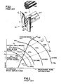
- a conventional IDC is generally designated by the reference numeral 10.
- conventional IDCs consist of two fairly rigid contact beams 12, 14 spaced from each other as shown and joined at one end by a base 16 to form a wire receiving slot 18.
- the contact beams 12,14 and the base 16 are typically die cut from a metallic plate or sheet material and are all located in a contact plane.
- the base 16 prevents significant movements of the contact beams 12,14 within the contact plane which separates the contact beams to significantly enlarge the size of the wire slot 18.
- the contact beams 12,14 are typically provided with inclined lead-in guide edges 20 and lead-in chamfers 22 to facilitate the insertion of a wire or wires 24 and maintain the same within the wire slot 18.
- the wire 24 consists either of a single conductor or includes a number of conductors which are stranded, a standard design 7-strand wire or conductor being shown in Fig. 1 without the insulator.
- the lead-in chamfers 22 cut and displace the wire insulation (not shown) and, as the wire is pushed further into the slot 18, there is typically a deformation of both the conductors 24 and the contact beams 12,14.
- the stranded conductors 24 are shown to assume a generally aligned condition along the length direction of the slot 18 in order to conform therewith.
- the contact beams 12,14 are shown in phantom outline in expanded positions 12',14' as previously indicated, the conductors 24, in assuming positions 24', will have mostly a plastic deformation while the contact beams 12,14 will have elastic deformation and deflect outwardly.
- the contact beams 12,14 are generally rigid and are deflected very small amounts, this being exaggerated in Fig. 1 for purposes of illustration.
- Fig. 2 shows the spring rate of a conventional IDC contact and the force-deformation curve for different wire sizes.
- the short, stiff beams of the conventional IDC have very little deflection. After wire sizing, the force is substantially reduced.
- the stiff contact beams of the prior art IDCs have been largely ineffective in rearranging the wire strands into the narrowest width shape. This results in less contact area between the wire strands and the contacts of the IDC and therefore the connection exhibits higher contact resistance.
- curves 26a-29a each represent the relative forces applied to wires of different sizes placed into an IDC slot.
- the curves 26a-29a represent wires of increasing size or diameter (e.g. 22AWG-16AWG).
- the deformation characteristics of a conventional IDC are designated by the reference numeral 30, the IDC applying zero force when undeflected and exhibiting a high deflection-force slope or ratio, the curve leveling off when the beams reach the limits of elastic deformation.
- each of the wire curves 26a-29a includes a relatively small portion 26b-29b, respectively, which are considered as satisfactory ranges of deformation, these ranges defining lines 32 and 34 which bound the satisfactory wire deformation zone or range R.
- the actual force applied to the wire represented by the curve 27a when placed into the conventional IDC is determined by the point of intersection between the curves 27a and 30, or at equilibrium point P1 where force F1 is applied to the wire.
- the conductor or wire strands typically exhibit plastic deformation in time and this effectively reduces the size or external dimensions of the conductors or strands. This effect is sometimes referred to as "sizing", and the effect of sizing on one strand represented by curve 27a is shown in dashed outline in Fig.
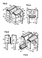
- the torsion IDC (TIDC) 36 includes a pair of substantially co-extensive U-shaped beams 38, 40 formed of flat sheet material as shown and laterally spaced from each other to form a longitudinal wire receiving channel or space 42.
- Each U-shaped beam 38, 40 has a contact beam portion 44, both spaced or opposed contact beam portions being arranged in a common contact plane as shown.
- a back supporting portion or base 45 Spaced behind the contact beam portions 44, as viewed in Fig. 3, there is provided a back supporting portion or base 45 which is parallel to the contact plane and which itself defines a support or mounting plane.
- Each of the contact beam portions 44 is provided with a contact 46 which is arranged in the contact plane and which projects into the wire receiving channel 42 as shown.
- Each of the contacts 46 is provided with a lead-in guide or edge 48, the two edges 48 of opposing contacts 46 sloping downwardly and inwardly, as viewed in Fig. 3, to provide a V-shaped lead-in edge to facilitate insertion of a wire and promote displacement of its insulation.
- the supporting portion or base 45 is shown to be provided with a strain relief slot 50, aligned with the wire receiving channel 42, to form rear torsion mounting beam portions 52 on each side of the strain relief slot 50.
- the dimensions of the strain relief slot 50 are such as to receive a wire and its insulation without significant deformation or insulation displacement.
- the wire is received within the strain relief slot in pressure contact or abutment so as to resist or inhibit longitudinal or axial displacements of the wire. This, as with other IDCs, eliminates or minimizes the strains which are applied to the conductors themselves between the contacts 46.
- inwardly directed lead in guide edges 54 which cut back normally to the edge of the slot so as to create inwardly directed barbs or hooks 56.
- barbs or hooks allow the wire to be placed or forced into the strain relief slot 50 but resists its movement out of the slot.
- curved transverse top beam portions 58 Extending between the front contact beam portions 44 and the rear mounting beam portions 52 are curved transverse top beam portions 58. The slight curvature of the transverse beam portions 58 is best shown in Fig. 4. Extending downwardly from the supporting portion or base 45, as viewed in Figs. 3 and 4, are mounting legs 60 which are dimensioned to be received within mounting holes of a printed circuit board 62.
- the various contact, mounting and transverse beam portions 46, 52 and 58, respectively, are all die cut or punched from flat sheet material, the U-shaped configuration being formed during separate bending steps.
- an elongate transverse depression 64 in the supporting portion or base 45 to enhance the rigidity and strength thereof.
- a wire W which includes stranded conductors 24 and an insulation I.
- the wire W is shown forced between the contacts 46.
- the separation of the contacts 46 exerts certain opposing forces F (Fig. 3) on the contacts 46, and these forces torsionally deform the beam portions 44, 52 and 58.
- F Fig. 3
- the IDC has improved flexibility and ability to sustain separation of the contacts 46 without plastic deformation.
- the torsional deformations within the beam portions act to resist the forces F and to urge the contacts 46 towards each other.
- the contacts 46 have upper portions 46a reduced in size to form a contact slot 46b at the upper end of the contacts, while the lower ends of the contacts 46c are as in the previous embodiment.
- the contacts 46c also join at a separation line 46'.
- the IDC 36a is better suited for low wire gauges which have larger external dimensions thereby making it possible to accommodate such large wires without unduly damaging the conductors by applying excessive forces thereto.
- the IDCs 36 and 36a exhibit high force, high deflection, and low stiffness.
- An important feature of the present invention is that the contacts 46, 46c may abut each other with zero force or may be urged against each other with a preset force called preload.
- Preload is set by forming the top torsion beam portions 58. Preload can also be set by slightly curving the rear mounting beam portions 52 and the rear supporting portion or base 45. With the proper preload, the minimum contact force, the range of the wire sizes, and even the wire strand rearrangement can be controlled effectively.
- the edges When a wire is pushed against the coined V-shaped insulation shear edges or lead-in-guide edges 48, the edges will cut the wire insulation. If the wire is pushed further between the contacts, the IDC slot will open up. This slot can be opened up to a width, larger than the wire diameter, without taking a permanent set, so that it can receive the total full diameter of the stranded wire. At this stage, the terminal beams are in a maximum force-maximum deflection position and exert high normal forces F on the wire.
- the high normal forces F combined with the downward movement of the wire will rearrange the wire strands 24' into their narrowest shape, and in the case of a stranded wire, one single line (if the wire strands are not bundled too tightly).
- the front contact beam portions 44 will close in on the wire strands and keep them under contact pressure.
- the ability of the torsion IDC to achieve this large force, large deflection characteristic can best be explained by a stress analysis. when a force F is applied to the center of the two front contacts 46, as shown in Fig. 3, the two front contact beam portions 44 are under bending load.
- the top or transverse beam portions 58 are under a combined load of torsion and bending load and the mounting beam portions 52 are also on the torsion and bending load.
- the deflection of the wire is the sum of the angular deflection of the beams under torsion load and the beam deflection under bending load. Numerical analyses show that the deflection from the torsion load is much larger than the deflection from the bending load.
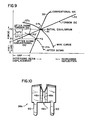
- a force-deflection diagram is shown for a conventional IDC, the torsion IDC and the force-deformation curves for different size wires.
- the points of intersection of such curves and the IDC curves represent equilibrium points. Since the preloads can be set independently (without changing the stiffness of the torsion IDC), the IDC torsion-deflection curve can be moved up or down so that it intersects the maximum number of different wire sizes in the satisfactory deformation range R.
- the torsion IDC with zero preload provides acceptable connection for only two wire sizes, represented by curves 28a and 29a.
- the IDC can terminate five or more wire sizes.
- a terminal which has been produced by Zierick Manufacturing Corporation can terminate a range of wire sizes from 18 to 26 AWG. It will also be appreciated that because of the high slope exhibited by the conventional IDC, it will frequently terminate only one, or at most, two wire sizes.
- Fig. 10 there is shown another version of the torsion IDC 36b, wherein there is provided a tapered wire conduit or slot 46a which widens at the lower part of the terminal, as viewed in Fig. 10.
- the angle of the taper can be adjusted by setting the preload correctly.
- the preload is not uniform along the length of the wire conduit slot, it is larger near the insulation shear edges 48.
- a slightly tapered wire slot 46a improves the connector's reliability. If there is wire strand movement as a result of vibration or temperature change, the strands will move to the direction of least resistance, which is downward, as viewed in Fig. 10, where the slot is slightly wider.
- the lower end of the slot is closed off by the PC board 62 so the wire strands cannot leave the slot.
- the wire insertion force is increased to the maximum while the insulation is cut and the wire opens up the wire slot 46a. From this maximum level, the wire insertion force will rapidly decrease to a minimum while the wire is pushed down into the slot. This gives a snap-in effect. It is advantageous that when the wire is inserted with a hand tool (field termination) it gives a good feedback. Where the operator pushes the hand wire insertion tool with an increasing force, the wire does not move until the force reaches the termination force level. Then the wire just snaps all the way into the slot. Half way insertions are thereby avoided. On a conventional IDC terminal, the wire insertion effect is just the opposite.
- the IDC in accordance with the present invention is not sensitive to the relative motion between the wire and the terminal.
- the strain relief slot 50 on the back supporting portion or base 45 works well as a wire strain relief by holding the wire firmly in place.
- the two hooks, barbs or dimples 56 prevents the wire from coming out of the strain relief slot.
- this strain relief slot with hooks simplifies wire insertion during assembly.
- the wire can be pushed in and seated in the strain relief slot 50 by hand. This keeps a section of the wire lined up with the V-groove typically provided on the insertion tool which terminates the wire by inserting it into the wire slot.
- FIG. 11 While the embodiments 36,36a and 36b have been described in connection with a PC-board wire termination, the same or similar design principles can be used in connection with other wire terminations and other electrical applications involving the terminations of a wire or cable.
- the terminal 64 while the lower end of the separation slot 46' or slot between the contacts 46 is normally closed by the PC board 62 when mounted thereon, it is also possible to use a terminal 64, wherein the terminal body 66 closes the separation line 46' at the end thereof opposite to the load in guide edges 48.
- the IDC connector 36c of Fig. 11 includes a female receptacle 68 at the end of the terminal body 66 opposite from where the IDC structure is mounted.
- the IDC portion of the connector 36c operates in the way previously described in connection with IDCs 36,36a and 36b.
- the same IDC terminal construction can mate not only with wire but with other electrical components.
- Terminals designed for 14 AWG wire sizes and larger preferably have an open slot 46c between the contact beam portions 44. No preload is possible in this configuration, since the contact beam portions 44 do not abut against each other. However, the normal forces on the wire can be made high when the terminal can be made from a thicker material.
- Similar IDC constructions can be made which can mate not only with wire but also with tabs. Referring to Fig.
- the IDC 36e is similar to IDC 36 of Fig. 3, except that diverging edges 46d are formed on each contact beam portion 44 to create an inverse V-shaped area and resulting point contacts 46f between the inclined edges on either side thereof.
- a low profile fuse clip which utilizes the principles of the IDC construction in accordance with the invention, which takes advantage of the high deflection of the torsion design.
- the contact beam portions 44 are provided with a circular receiving opening 46f created by the circular or curved edges 46g which are selected to have a diameter substantially corresponding to the fuse 72 cylindrical metallic caps or contacts 74. Since the IDC 36f is not used to terminate a wire, no strain relief slot is required.
- cut outs 52a may be provided and laterally spaced from each other in the back supporting portion or base 45 so as to create a resilient or flexible spring finger plate 52c which abuts against the metallic caps or contacts 74 when the fuse 72 is snapped into the IDCs to thereby prevent longitudinal movements of the fuse 72 and insure that the fuse remains within the fuse clip.
- the edges 46g are spaced from each other so as to abut against the metallic caps or contacts 74 in pressure relationship to insure good contact and low contact resistance.
- the IDC terminal in accordance with the present invention is designed for a large range of wire sizes and dozens of mating cycles.
- a single terminal can accommodate a range from 18 to 28 AWG, while the maximum stress in the terminal remains below 70 percent of yield stress, so no permanent set and very little stress relaxation takes place.
- Cross-sections of the terminations show wire deformation ranges of 15-40 percent depending on wire sizes. With stranded wire, the deformation range 5-15 percent. With 7 strand stranded wire most of the time the wire strands get rearranged into one single line, but not consistently because of other variables. When the wire is removed from the slot the terminal returns to its original zero gap position without the loss of the preload force between the contacts 46, which is sufficient to maintain a good contact. Contact resistance measurements before and after accelerated aging and temperature shock show less than 9 percent maximum change in contact resistance.
Landscapes
- Connections By Means Of Piercing Elements, Nuts, Or Screws (AREA)
- Coupling Device And Connection With Printed Circuit (AREA)
- Details Of Connecting Devices For Male And Female Coupling (AREA)
- Fuses (AREA)
Applications Claiming Priority (2)
| Application Number | Priority Date | Filing Date | Title |
|---|---|---|---|
| US07/458,142 US5022868A (en) | 1989-12-28 | 1989-12-28 | Torsion insulation displacement connector |
| US458142 | 1989-12-28 |
Publications (2)
| Publication Number | Publication Date |
|---|---|
| EP0435292A1 true EP0435292A1 (de) | 1991-07-03 |
| EP0435292B1 EP0435292B1 (de) | 1995-09-06 |
Family
ID=23819541
Family Applications (1)
| Application Number | Title | Priority Date | Filing Date |
|---|---|---|---|
| EP90125590A Expired - Lifetime EP0435292B1 (de) | 1989-12-28 | 1990-12-27 | Torsionsschneidklemmverbinder |
Country Status (4)
| Country | Link |
|---|---|
| US (1) | US5022868A (de) |
| EP (1) | EP0435292B1 (de) |
| AT (1) | ATE127622T1 (de) |
| DE (1) | DE69022199T2 (de) |
Cited By (2)
| Publication number | Priority date | Publication date | Assignee | Title |
|---|---|---|---|---|
| US6296513B1 (en) | 2000-05-17 | 2001-10-02 | Tyco Electronics Amp, K.K. | Electrical terminal for terminating at least two wires therein |
| EP1158609A1 (de) * | 2000-05-26 | 2001-11-28 | The Whitaker Corporation | Elektrisches Anschlussteil |
Families Citing this family (18)
| Publication number | Priority date | Publication date | Assignee | Title |
|---|---|---|---|---|
| US5417582A (en) * | 1993-10-18 | 1995-05-23 | Tang; Wen-Yun | Connector terminals for use in computers |
| US5611709A (en) * | 1995-08-10 | 1997-03-18 | Valleylab Inc | Method and assembly of member and terminal |
| US6132236A (en) * | 1999-05-14 | 2000-10-17 | Methode Electronics, Inc. | Flex cable termination apparatus and termination method |
| US6524127B2 (en) * | 2001-06-18 | 2003-02-25 | Illinois Tool Works | Insulation displacement connector with reversed bevel cutting edge contacts |
| DE20120690U1 (de) * | 2001-12-20 | 2003-02-13 | Weidmüller Interface GmbH & Co., 32760 Detmold | Reihenklemme mit Leiterplatte |
| US7564337B2 (en) * | 2005-03-03 | 2009-07-21 | Littelfuse, Inc. | Thermally decoupling fuse holder and assembly |
| US7753715B2 (en) | 2006-01-04 | 2010-07-13 | Anthony Freakes | Electrical connector devices and methods for employing same |
| US7530827B2 (en) * | 2007-05-22 | 2009-05-12 | Penduit Corp. | Raceway IDC connector |
| US8366497B2 (en) * | 2009-06-17 | 2013-02-05 | Lear Corporation | Power terminal |
| US7927127B1 (en) | 2009-10-16 | 2011-04-19 | Lear Corporation | Electrical terminal device |
| DE102011011151B4 (de) | 2010-11-24 | 2014-12-04 | Lear Corporation | Anschlussbuchsenanordnung für eine elektrische Steckverbindung |
| US8951051B2 (en) | 2011-10-10 | 2015-02-10 | Lear Corporation | Connector having optimized tip |
| EP2987210A4 (de) | 2013-04-18 | 2016-12-14 | Fci Asia Pte Ltd | Schneidklemmverbinder und kontakte dafür |
| WO2015017493A1 (en) | 2013-07-30 | 2015-02-05 | FCI Asia Pte. Ltd. | Insulation displacement connector |
| US9543664B2 (en) | 2013-08-02 | 2017-01-10 | Fci Americas Technology Llc | Insulation displacement connector |
| US10050395B2 (en) | 2013-12-06 | 2018-08-14 | Fci Usa Llc | Cable for electrical power connection |
| EP3024093B1 (de) | 2014-11-21 | 2019-01-02 | TE Connectivity Nederland B.V. | Isolationsverlagerungs-Kontaktvorrichtung |
| US10312608B2 (en) | 2015-03-03 | 2019-06-04 | Fci Usa Llc | Insulation displacement connector |
Citations (4)
| Publication number | Priority date | Publication date | Assignee | Title |
|---|---|---|---|---|
| US4043628A (en) * | 1976-06-18 | 1977-08-23 | Thomas & Betts Corporation | Electrical contact |
| GB2050712A (en) * | 1979-05-23 | 1981-01-07 | Souriau & Cie | Self-stripping terminal for an electrical connector |
| DE3511034C1 (de) * | 1985-03-27 | 1986-06-05 | Friemann & Wolf Gerätebau GmbH, 4100 Duisburg | U-förmige Halterungsklammer für Schmelzsicherungen |
| US4834670A (en) * | 1988-02-16 | 1989-05-30 | General Motors Corporation | Insulation displacement terminal assembly |
Family Cites Families (3)
| Publication number | Priority date | Publication date | Assignee | Title |
|---|---|---|---|---|
| US3854114A (en) * | 1972-08-10 | 1974-12-10 | J Kloth | Notched plate clasp apparatus |
| US4074929A (en) * | 1973-08-29 | 1978-02-21 | Amp Incorporated | Cable card edge connector |
| US4116522A (en) * | 1976-07-09 | 1978-09-26 | Amp Incorporated | Slotted terminal |
-
1989
- 1989-12-28 US US07/458,142 patent/US5022868A/en not_active Expired - Lifetime
-
1990
- 1990-12-27 AT AT90125590T patent/ATE127622T1/de not_active IP Right Cessation
- 1990-12-27 DE DE69022199T patent/DE69022199T2/de not_active Expired - Lifetime
- 1990-12-27 EP EP90125590A patent/EP0435292B1/de not_active Expired - Lifetime
Patent Citations (4)
| Publication number | Priority date | Publication date | Assignee | Title |
|---|---|---|---|---|
| US4043628A (en) * | 1976-06-18 | 1977-08-23 | Thomas & Betts Corporation | Electrical contact |
| GB2050712A (en) * | 1979-05-23 | 1981-01-07 | Souriau & Cie | Self-stripping terminal for an electrical connector |
| DE3511034C1 (de) * | 1985-03-27 | 1986-06-05 | Friemann & Wolf Gerätebau GmbH, 4100 Duisburg | U-förmige Halterungsklammer für Schmelzsicherungen |
| US4834670A (en) * | 1988-02-16 | 1989-05-30 | General Motors Corporation | Insulation displacement terminal assembly |
Cited By (2)
| Publication number | Priority date | Publication date | Assignee | Title |
|---|---|---|---|---|
| US6296513B1 (en) | 2000-05-17 | 2001-10-02 | Tyco Electronics Amp, K.K. | Electrical terminal for terminating at least two wires therein |
| EP1158609A1 (de) * | 2000-05-26 | 2001-11-28 | The Whitaker Corporation | Elektrisches Anschlussteil |
Also Published As
| Publication number | Publication date |
|---|---|
| EP0435292B1 (de) | 1995-09-06 |
| DE69022199T2 (de) | 1996-04-04 |
| US5022868A (en) | 1991-06-11 |
| DE69022199D1 (de) | 1995-10-12 |
| ATE127622T1 (de) | 1995-09-15 |
Similar Documents
| Publication | Publication Date | Title |
|---|---|---|
| US5022868A (en) | Torsion insulation displacement connector | |
| EP0630071B1 (de) | Drahtverbindungsanordnung aus Metallblech | |
| US5588884A (en) | Stamped and formed contacts for a power connector | |
| US4261629A (en) | Slotted plate terminal | |
| KR950004365B1 (ko) | 전기접촉부재 | |
| US4040702A (en) | Solderless termination system | |
| EP2483969B1 (de) | Einteilige leitfähige klemme für einen einführungsdraht-stecker | |
| EP0279508A1 (de) | Elektrische Anschlussklemme | |
| US5030132A (en) | Bidirectional insulation displacement electrical contact terminal | |
| US5139434A (en) | Strain relief for insulation displacement contact | |
| CA1215152A (en) | Cable clamp for an electrical connector | |
| US6010377A (en) | High contact force pin-receiving electrical terminal | |
| JPS63264880A (ja) | 切断・クランプスリーブ接点 | |
| EP0191539B1 (de) | Elektrisches Anschlussendstück für Steckverbinder | |
| JPH0744046B2 (ja) | 絶縁穿孔導電端子 | |
| CA1150378A (en) | Slotted plate terminal renewable as spade terminal | |
| US4231632A (en) | Contact element for insulation pierce type | |
| US5026301A (en) | Lead termination | |
| EP0240552B1 (de) | Isolationdurchdringender kontakt | |
| US4813884A (en) | High contact pressure insulation displacement terminal for multi-strand wire | |
| US4480385A (en) | Tool and method for terminating electrical conductors in contact members | |
| EP0147218A2 (de) | Die Isolation durchstechender Pressverbinder | |
| GB2130815A (en) | Electrical connectors | |
| GB2115990A (en) | Insulation-piercing electrical terminal | |
| IE78623B1 (en) | Insulation displacement contact element |
Legal Events
| Date | Code | Title | Description |
|---|---|---|---|
| PUAI | Public reference made under article 153(3) epc to a published international application that has entered the european phase |
Free format text: ORIGINAL CODE: 0009012 |
|
| AK | Designated contracting states |
Kind code of ref document: A1 Designated state(s): AT BE CH DE DK ES FR GB GR IT LI LU NL SE |
|
| 17P | Request for examination filed |
Effective date: 19920102 |
|
| 17Q | First examination report despatched |
Effective date: 19940513 |
|
| GRAA | (expected) grant |
Free format text: ORIGINAL CODE: 0009210 |
|
| AK | Designated contracting states |
Kind code of ref document: B1 Designated state(s): AT BE CH DE DK ES FR GB GR IT LI LU NL SE |
|
| PG25 | Lapsed in a contracting state [announced via postgrant information from national office to epo] |
Ref country code: IT Free format text: LAPSE BECAUSE OF FAILURE TO SUBMIT A TRANSLATION OF THE DESCRIPTION OR TO PAY THE FEE WITHIN THE PRE;WARNING: LAPSES OF ITALIAN PATENTS WITH EFFECTIVE DATE BEFORE 2007 MAY HAVE OCCURRED AT ANY TIME BEFORE 2007. THE CORRECT EFFECTIVE DATE MAY BE DIFFERENT FROM THE ONE RECORDED.SCRIBED TIME-LIMIT Effective date: 19950906 Ref country code: ES Free format text: THE PATENT HAS BEEN ANNULLED BY A DECISION OF A NATIONAL AUTHORITY Effective date: 19950906 Ref country code: GR Free format text: LAPSE BECAUSE OF FAILURE TO SUBMIT A TRANSLATION OF THE DESCRIPTION OR TO PAY THE FEE WITHIN THE PRESCRIBED TIME-LIMIT Effective date: 19950906 Ref country code: DK Effective date: 19950906 Ref country code: FR Effective date: 19950906 Ref country code: NL Free format text: LAPSE BECAUSE OF NON-PAYMENT OF DUE FEES Effective date: 19950906 Ref country code: BE Effective date: 19950906 Ref country code: AT Effective date: 19950906 |
|
| REF | Corresponds to: |
Ref document number: 127622 Country of ref document: AT Date of ref document: 19950915 Kind code of ref document: T |
|
| REF | Corresponds to: |
Ref document number: 69022199 Country of ref document: DE Date of ref document: 19951012 |
|
| PG25 | Lapsed in a contracting state [announced via postgrant information from national office to epo] |
Ref country code: SE Effective date: 19951206 |
|
| PGFP | Annual fee paid to national office [announced via postgrant information from national office to epo] |
Ref country code: GB Payment date: 19951214 Year of fee payment: 6 |
|
| PG25 | Lapsed in a contracting state [announced via postgrant information from national office to epo] |
Ref country code: LU Free format text: LAPSE BECAUSE OF NON-PAYMENT OF DUE FEES Effective date: 19951231 |
|
| PGFP | Annual fee paid to national office [announced via postgrant information from national office to epo] |
Ref country code: CH Payment date: 19951231 Year of fee payment: 6 |
|
| NLV1 | Nl: lapsed or annulled due to failure to fulfill the requirements of art. 29p and 29m of the patents act | ||
| EN | Fr: translation not filed | ||
| REG | Reference to a national code |
Ref country code: CH Ref legal event code: PL |
|
| PLBE | No opposition filed within time limit |
Free format text: ORIGINAL CODE: 0009261 |
|
| STAA | Information on the status of an ep patent application or granted ep patent |
Free format text: STATUS: NO OPPOSITION FILED WITHIN TIME LIMIT |
|
| 26N | No opposition filed | ||
| PG25 | Lapsed in a contracting state [announced via postgrant information from national office to epo] |
Ref country code: GB Effective date: 19961227 |
|
| PG25 | Lapsed in a contracting state [announced via postgrant information from national office to epo] |
Ref country code: LI Free format text: LAPSE BECAUSE OF FAILURE TO SUBMIT A TRANSLATION OF THE DESCRIPTION OR TO PAY THE FEE WITHIN THE PRESCRIBED TIME-LIMIT Effective date: 19961231 Ref country code: CH Free format text: LAPSE BECAUSE OF FAILURE TO SUBMIT A TRANSLATION OF THE DESCRIPTION OR TO PAY THE FEE WITHIN THE PRESCRIBED TIME-LIMIT Effective date: 19961231 |
|
| GBPC | Gb: european patent ceased through non-payment of renewal fee |
Effective date: 19961227 |
|
| PGFP | Annual fee paid to national office [announced via postgrant information from national office to epo] |
Ref country code: DE Payment date: 20091224 Year of fee payment: 20 |
|
| PG25 | Lapsed in a contracting state [announced via postgrant information from national office to epo] |
Ref country code: DE Free format text: LAPSE BECAUSE OF EXPIRATION OF PROTECTION Effective date: 20101227 |