EP0435375A2 - Verfahren und Gerät zur Bestimmung der Füllzeit von einer Getriebekupplung und Bremse - Google Patents
Verfahren und Gerät zur Bestimmung der Füllzeit von einer Getriebekupplung und Bremse Download PDFInfo
- Publication number
- EP0435375A2 EP0435375A2 EP90203329A EP90203329A EP0435375A2 EP 0435375 A2 EP0435375 A2 EP 0435375A2 EP 90203329 A EP90203329 A EP 90203329A EP 90203329 A EP90203329 A EP 90203329A EP 0435375 A2 EP0435375 A2 EP 0435375A2
- Authority
- EP
- European Patent Office
- Prior art keywords
- fluid
- fill time
- torque transmitting
- function
- determining
- Prior art date
- Legal status (The legal status is an assumption and is not a legal conclusion. Google has not performed a legal analysis and makes no representation as to the accuracy of the status listed.)
- Granted
Links
Images

Classifications
-
- F—MECHANICAL ENGINEERING; LIGHTING; HEATING; WEAPONS; BLASTING
- F16—ENGINEERING ELEMENTS AND UNITS; GENERAL MEASURES FOR PRODUCING AND MAINTAINING EFFECTIVE FUNCTIONING OF MACHINES OR INSTALLATIONS; THERMAL INSULATION IN GENERAL
- F16H—GEARING
- F16H61/00—Control functions within control units of change-speed- or reversing-gearings for conveying rotary motion ; Control of exclusively fluid gearing, friction gearing, gearings with endless flexible members or other particular types of gearing
- F16H61/04—Smoothing ratio shift
- F16H61/06—Smoothing ratio shift by controlling rate of change of fluid pressure
- F16H61/061—Smoothing ratio shift by controlling rate of change of fluid pressure using electric control means
-
- F—MECHANICAL ENGINEERING; LIGHTING; HEATING; WEAPONS; BLASTING
- F16—ENGINEERING ELEMENTS AND UNITS; GENERAL MEASURES FOR PRODUCING AND MAINTAINING EFFECTIVE FUNCTIONING OF MACHINES OR INSTALLATIONS; THERMAL INSULATION IN GENERAL
- F16H—GEARING
- F16H59/00—Control inputs to control units of change-speed- or reversing-gearings for conveying rotary motion
- F16H59/68—Inputs being a function of gearing status
- F16H2059/6807—Status of gear-change operation, e.g. clutch fully engaged
-
- F—MECHANICAL ENGINEERING; LIGHTING; HEATING; WEAPONS; BLASTING
- F16—ENGINEERING ELEMENTS AND UNITS; GENERAL MEASURES FOR PRODUCING AND MAINTAINING EFFECTIVE FUNCTIONING OF MACHINES OR INSTALLATIONS; THERMAL INSULATION IN GENERAL
- F16H—GEARING
- F16H61/00—Control functions within control units of change-speed- or reversing-gearings for conveying rotary motion ; Control of exclusively fluid gearing, friction gearing, gearings with endless flexible members or other particular types of gearing
- F16H2061/0075—Control functions within control units of change-speed- or reversing-gearings for conveying rotary motion ; Control of exclusively fluid gearing, friction gearing, gearings with endless flexible members or other particular types of gearing characterised by a particular control method
- F16H2061/0087—Adaptive control, e.g. the control parameters adapted by learning
-
- F—MECHANICAL ENGINEERING; LIGHTING; HEATING; WEAPONS; BLASTING
- F16—ENGINEERING ELEMENTS AND UNITS; GENERAL MEASURES FOR PRODUCING AND MAINTAINING EFFECTIVE FUNCTIONING OF MACHINES OR INSTALLATIONS; THERMAL INSULATION IN GENERAL
- F16H—GEARING
- F16H61/00—Control functions within control units of change-speed- or reversing-gearings for conveying rotary motion ; Control of exclusively fluid gearing, friction gearing, gearings with endless flexible members or other particular types of gearing
- F16H61/04—Smoothing ratio shift
- F16H61/06—Smoothing ratio shift by controlling rate of change of fluid pressure
- F16H61/061—Smoothing ratio shift by controlling rate of change of fluid pressure using electric control means
- F16H2061/062—Smoothing ratio shift by controlling rate of change of fluid pressure using electric control means for controlling filling of clutches or brake servos, e.g. fill time, fill level or pressure during filling
-
- F—MECHANICAL ENGINEERING; LIGHTING; HEATING; WEAPONS; BLASTING
- F16—ENGINEERING ELEMENTS AND UNITS; GENERAL MEASURES FOR PRODUCING AND MAINTAINING EFFECTIVE FUNCTIONING OF MACHINES OR INSTALLATIONS; THERMAL INSULATION IN GENERAL
- F16H—GEARING
- F16H59/00—Control inputs to control units of change-speed- or reversing-gearings for conveying rotary motion
- F16H59/68—Inputs being a function of gearing status
- F16H59/72—Inputs being a function of gearing status dependent on oil characteristics, e.g. temperature, viscosity
Definitions
- This invention relates to a method and apparatus for determining the fill time required substantially to fill with fluid a torque transmitting device of an automatic transmission for a vehicle.
- a motor vehicle automatic transmission includes a number of gear elements coupling its input and output shafts, and a related number of torque establishing devices such as clutches and brakes which are selectively engageable to activate certain gear elements for establishing a desired speed ratio between the input and output shafts.
- the brake can be of the band-type or disc-type. Automotive engineers commonly refer to disc-type brakes in transmissions as “clutches” or “reaction clutches”. As used herein, the terms “clutches” and “torque transmitting devices” will be used to refer to brakes as well as clutches.
- the input shaft is connected to the vehicle engine through a fluid coupling, such as a torque converter, and the output shaft is connected directly to the vehicle wheels. Shifting from one forward speed ratio to another is performed in response to engine throttle and vehicle speed, and generally involves releasing or disengaging the clutch (off-going) associated with the current speed ratio and applying or engaging the clutch (on-coming) associated with the desired speed ratio.
- a fluid coupling such as a torque converter
- the speed ratio is defined as the transmission input speed or turbine speed divided by the output speed.
- a low gear range has a high speed ratio and a higher gear range has a lower speed ratio.
- a shift is made from a high speed ratio to a low speed ratio.
- the upshift is accomplished by disengaging a clutch associated with the higher speed ratio and engaging a clutch associated with the lower speed ratio, thereby to reconfigure the gear set to operate at the lower speed ratio. Shifts performed in the above manner are termed clutch-to-clutch shifts and require precise timing in order to achieve high quality shifting.
- the shift quality of a control based on calibrated or preset times is often dependent on reliable estimation of the fill time of an on-coming clutch.
- Fill time is the time required to fill a clutch cavity with oil. During the fill period the clutch piston strokes and the clutch plates compress. No significant clutch capacity can occur until this compression is complete. Hence, it is very important for proper clutch control during range shifting of an automatic transmission to be able to predetermine accurately the length of the fill period. Under-estimation of the fill period results in little or no clutch capacity when clutch application is required; over-estimation of the fill period results in excessive clutch pressure being applied.
- the fill time required to achieve torque carrying capacity is a variable, depending mainly on the size of the clutch fill volume, the fluid pump speed, and the fluid temperature. It is important to know when, after fill initiation, to expect the clutch to assume torque capacity in order to time other shift commands.
- the method takes into account varying pump speed, fluid temperature and clutch volume.
- apparatus for determining the fill time required substantially to fill with fluid a torque transmitting device of an automatic transmission for a vehicle as defined in claim 6.
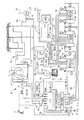
- the reference numeral 10 generally designates a motor vehicle drive train which includes a throttled internal combustion engine 12, a fluidic torque converter 14, a six-speed fluid operated power transmission 16 and a differential gear set (DG) 18.
- the engine 12 is connected to the torque converter 14 via shaft 20
- the torque converter 14 is connected to the transmission 16 via shaft 22
- the transmission 16 is connected to the differential gear set 18 via shaft 24
- the differential gearset is connected to a pair of drive wheels (not shown) via the prop shafts 26 and 28.
- the speed and torque relationships between the engine 12 and the drive wheels of the vehicle are controlled by a fluid operated torque converter clutch, designated TCC, and five fluid operated transmission clutches, designated C1 - C5.
- the torque converter clutch TCC is selectively engaged by the solenoid operated control valve 30 to connect mechanically the impeller I and turbine T of torque converter 14.
- the clutches TCC, C1, C2, C3, C4, C5 are selectively engaged and disengaged by the solenoid operated control valves 30, 32, 34, 36, 38, 40, according to the diagram shown in Figure 1b, selectively to establish a desired transmission speed ratio.
- the illustrated transmission gear set provides one reverse ratio and six forward ratios, and is described in detail in U.S. Patent 4,070,927.
- An operator actuated accelerator pedal 41 positions the engine throttle for controlling the engine power output.
- the operation of the solenoid operated control valves 30 - 40 is controlled by a computer-based control unit 42, shown in dotted outline, via lines 44 - 54 in response to various input signals representative of system parameters.
- Such inputs include an engine throttle position signal %T on line 56, an engine output shaft speed signal Ne on line 58, a torque converter output shaft speed signal Nt on line 60, a transmission output shaft speed signal No on line 62, a system supply voltage signal Vb on line 64, a transmission fluid temperature signal Tsump on line 66, and an operator range selector position signal RS on line 68.
- the system voltage is supplied by the storage battery 70, and the input signals are obtained with conventional electrical transducers such as potentiometers, thermistors and magnetic speed pickups.
- control unit 42 comprises a number of conventional devices including a microcomputer (uC) with internal clock and memory, an input/output device (I/O) and an array of pulse width modulated signal generators (PWM) and drivers (DR).
- a PWM generator and a driver (DR) are dedicated to each solenoid operated control valve 30 - 40.
- the PWM generator outputs are delivered to the respective drivers (DR) and are used to energize the respective solenoid operated control valves.
- the duty cycle of the PWM generator outputs determines the hydraulic pressure supplied by the solenoid operated control valves, with a low percent duty cycle yielding a low pressure and a high percent duty cycle yielding a high pressure for a normally closed valve.
- the hydraulic circuit of transmission 16 includes a positive displacement pump 82 driven by the engine at engine speed Ne for supplying pressurized hydraulic fluid from the sump or reservoir 84, to the clutches TCC and C1 - C5 through various hydraulic and electro-hydraulic valving mechanisms. After passing through a main circuit filter 86, the fluid output of pump 82 is directed to a main pressure regulator valve 88 which develops regulated fluid pressures in lines 90 and 92.
- the fluid in line 90 is directed through the torque converter 14, as schematically designated by the converter shell 97. After passing through a cooler 100 and cooler filter 102, the converter fluid is then regulated down to a lower pressure by the regulator valve 104 and directed to the transmission lube, or lubricant circuit 106.
- the fluid in line 92 is supplied as an input to the solenoid operated control valves 30 - 40, and also to the control pressure regulator valve 96.
- the control pressure regulator valve 96 develops a somewhat lower pressure in line 98, referred to herein as the control pressure, such pressure being directed to the solenoid of each control valve 30 - 40.
- the fluid in line 94 referred to as the converter clutch pressure, is supplied directly by solenoid 30 to the torque converter clutch TCC to engage the same. This pressure is also supplied to the main pressure regulator valve 88 to provide a lower regulated line pressure in the converter lock-up mode.
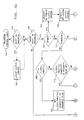
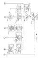
- Figures 2 and 3a - 3b are flow diagrams representative of computer program instructions executed by the computer-based control unit 42 of Figure 1 in changing from one gear to another.
- Figure 2 represents an executive or main loop program which directs the sequential execution of various subroutines.
- Block 130 designates a series of instructions executed at the initiation of each period of vehicle operation for setting the various timers, registers and variable values of control unit 42 to predetermined initial values. Thereafter, the blocks 132 - 140 are sequentially and repeatedly executed as indicated by the flow diagram lines.
- Block 132 reads the various input signal values and outputs the required control signals to the PWM generators and drivers for solenoid controlled valves 30 - 40.
- Blocks 134 - 138 contain diagnostic, shift scheduling, and adaptive flag logic.
- the clutch control logic block 140 analyzes the various system input signals described above in reference to Figure 1a, develops pressure command signals PCMD for application to the solenoid operated control valves at the next execution of block 132, and computes adaptive corrections based on the adaptive flags at shift completion. Block 140 also effects pulse-width-modulation of the solenoid drive voltage to carry out the pressure commands for specific shift operations. Block 140 is detailed in the flow chart of Figures 3a-3b.
- the flow diagram of Figures 3a - 3b sets forth the program for making decisions as to the type of range shift in progress, if any, and determines the specific control for the on-coming and the off-going clutches.
- the program also checks whether a shift has performed within specifications, and if not, certain shift parameters are changed at shift completion according to predefined adaptive logic to correct the shift.
- lockup clutch control is executed ⁇ 142> if a lockup shift is in progress ⁇ 144>.
- a range shift is in progress ⁇ 146>, it is determined whether it is an upshift ⁇ 150>, a downshift ⁇ 152>, a neutral shift ⁇ 154>, or a garage shift ⁇ 156>.
- a garage shift is a shift from neutral to either drive or reverse, or a shift from drive to reverse or from reverse to drive.
- the control flows from either the upshift, downshift, neutral shift or the garage shift block to the end-of-shift test ⁇ 160>.
- adaptive shift parameters are changed if required ⁇ 162> and the duty cycle command is output ⁇ 163>. If the shift has not ended ⁇ 160>, the duty cycle command is output ⁇ 163> before returning to the main loop of Figure 2.
- an upshift is indicated ⁇ 150>
- the upshift on-coming clutch control ⁇ 164> and the upshift off-going clutch control ⁇ 166> are activated.
- a downshift is indicated ⁇ 152>
- the powered downshift on-coming clutch control ⁇ 174> and the powered downshift off-going clutch control ⁇ 176> are activated. If the closed throttle flag is set ⁇ 173>, the throttle opened during the course of the closed throttle downshift and a transition to powered downshift may be necessary; in such case, the appropriate transition logic is invoked ⁇ 178>. If the shift is a neutral shift ⁇ 154>, the neutral shift clutch control executes shifts from drive to neutral or from reverse to neutral ⁇ 155>.
- Each control phase operates by setting pressures, pressure increments, times or other values to predefined calibrated values which are herein generally called “set”, “preset”, “given” or “certain” values.
- set is chosen from a table of calibrated values for each specific transmission condition, throttle range and shift type.
- different values are supplied for upshift, downshift, etc. as well as each range shift, e.g., 1-2, 2-1, 4-3, 5-4, etc.
- Converter and lockup modes may also require separate sets of calibration values.
- the base fill time is modified in this embodiment by a factor, referred to herein as the Exhaust Time Factor or ETF, which accounts for the presence of fluid retained in a clutch cavity from a previous apply period.
- ETF Exhaust Time Factor
- the fill time for a given clutch is thus calculated as the product of the base fill time, the volume ratio VR and the exhaust time factor ETF.
- the Base Fill Time varies according to several outside factors, primarily fluid temperature and pump speed. Low pump speed can limit the available flow of fluid and hence the time of clutch fill. Fluid leakage increases at high temperatures and reduces the effect of pump speed, at least at low pump speeds. At high pump speeds, flow restrictions become significant. This is especially true at low fluid temperatures due to the increased viscosity of the fluid.
- the effect of leakage as a function of temperature is determined empirically.
- the control provided compensates for the leakage effect by determining the effective pump speed in relation to the oil temperature.
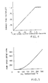
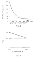
- the pump speed, or offset, corresponding to the leakage is typically nonlinear, as shown in Figure 5.
- the effective pump speed is the measured pump speed less the offset.
- the relationship between effective pumping speed and base fill time is determined empirically and is shown in Figure 6 for a typical clutch. It can be seen that at relatively low speeds, the base fill time changes dramatically with effective pumping speed.
- the fill time calculation for a respective clutch begins with measuring the pump speed (engine speed, Ne) and the fluid temperature.
- the Exhaust Time Factor ETF is then determined in relation to the time since the most recent clutch exhaust command was given, as illustrated in Figure 4.
- the leakage offset is then determined as a function of the oil temperature, as illustrated in Figure 5, and subtracted from the measured pump speed to obtain the Effective Pumping Speed.
- the Base Fill Time is then determined as a function of the effective pumping speed, as illustrated in Figure 6.
- the value of Ktemp is determined as illustrated in Figure 7, and multiplied with the Base Fill Time at Nmax to correct that value. Finally, the fill time is computed by multiplying the Base Fill Time by the Volume Ratio VR for the on-coming clutch and the Exhaust Time Factor ETF.
Landscapes
- Engineering & Computer Science (AREA)
- General Engineering & Computer Science (AREA)
- Physics & Mathematics (AREA)
- Fluid Mechanics (AREA)
- Mechanical Engineering (AREA)
- Control Of Transmission Device (AREA)
- Loading And Unloading Of Fuel Tanks Or Ships (AREA)
Applications Claiming Priority (2)
| Application Number | Priority Date | Filing Date | Title |
|---|---|---|---|
| US45642889A | 1989-12-26 | 1989-12-26 | |
| US456428 | 1995-06-01 |
Publications (3)
| Publication Number | Publication Date |
|---|---|
| EP0435375A2 true EP0435375A2 (de) | 1991-07-03 |
| EP0435375A3 EP0435375A3 (en) | 1992-02-26 |
| EP0435375B1 EP0435375B1 (de) | 1995-04-05 |
Family
ID=23812729
Family Applications (1)
| Application Number | Title | Priority Date | Filing Date |
|---|---|---|---|
| EP90203329A Expired - Lifetime EP0435375B1 (de) | 1989-12-26 | 1990-12-13 | Verfahren und Gerät zur Bestimmung der Füllzeit von einer Getriebekupplung und Bremse |
Country Status (4)
| Country | Link |
|---|---|
| EP (1) | EP0435375B1 (de) |
| JP (1) | JPH0650144B2 (de) |
| CA (1) | CA2024602C (de) |
| DE (1) | DE69018416T2 (de) |
Cited By (9)
| Publication number | Priority date | Publication date | Assignee | Title |
|---|---|---|---|---|
| US5467854A (en) * | 1994-06-07 | 1995-11-21 | Caterpillar Inc. | Method of controlling clutch-to-clutch shifts for a powershift transmission |
| US5505100A (en) * | 1994-09-29 | 1996-04-09 | Caterpillar Inc. | Method of controlling interrupted shifts for a powershift transmission |
| US5551930A (en) * | 1995-04-13 | 1996-09-03 | Caterpillar Inc. | Adaptive control method for an automatic transmission |
| GB2300887A (en) * | 1995-04-13 | 1996-11-20 | Caterpillar Inc | Determination of fill time of a transmission clutch from transmission speed me asurements |
| EP0730112A3 (de) * | 1995-03-02 | 1998-03-04 | Honda Giken Kogyo Kabushiki Kaisha | Steuersystem für hydraulischen Druck eines hydraulisch betätigten Fahrzeuggetriebes |
| WO1998023884A1 (de) * | 1996-11-22 | 1998-06-04 | Zf Friedrichshafen Ag | Erhöhung der spontanität eines automatgetriebes |
| US5950789A (en) * | 1998-04-27 | 1999-09-14 | Caterpillar Inc. | End of fill detector for a fluid actuated clutch |
| US6115661A (en) * | 1998-04-09 | 2000-09-05 | Caterpillar Inc. | End-of-fill detector for a fluid actuated clutch |
| CN113531115A (zh) * | 2020-04-21 | 2021-10-22 | 现代自动车株式会社 | 用于车辆的离合器控制方法 |
Families Citing this family (1)
| Publication number | Priority date | Publication date | Assignee | Title |
|---|---|---|---|---|
| JP3393460B2 (ja) * | 1995-09-08 | 2003-04-07 | アイシン・エィ・ダブリュ株式会社 | 自動変速機の油圧制御装置 |
Family Cites Families (3)
| Publication number | Priority date | Publication date | Assignee | Title |
|---|---|---|---|---|
| US4653350A (en) * | 1985-11-29 | 1987-03-31 | General Motors Corporation | Adaptive direct pressure shift control for a motor vehicle transmission |
| AU612674B2 (en) * | 1987-06-24 | 1991-07-18 | Kabushiki Kaisha Komatsu Seisakusho | Transmission controller |
| US4875391A (en) * | 1988-04-29 | 1989-10-24 | Chrysler Motors Corporation | Electronically-controlled, adaptive automatic transmission system |
-
1990
- 1990-09-04 CA CA 2024602 patent/CA2024602C/en not_active Expired - Fee Related
- 1990-12-13 DE DE1990618416 patent/DE69018416T2/de not_active Expired - Lifetime
- 1990-12-13 EP EP90203329A patent/EP0435375B1/de not_active Expired - Lifetime
- 1990-12-26 JP JP2406906A patent/JPH0650144B2/ja not_active Expired - Lifetime
Cited By (12)
| Publication number | Priority date | Publication date | Assignee | Title |
|---|---|---|---|---|
| US5467854A (en) * | 1994-06-07 | 1995-11-21 | Caterpillar Inc. | Method of controlling clutch-to-clutch shifts for a powershift transmission |
| US5505100A (en) * | 1994-09-29 | 1996-04-09 | Caterpillar Inc. | Method of controlling interrupted shifts for a powershift transmission |
| EP0730112A3 (de) * | 1995-03-02 | 1998-03-04 | Honda Giken Kogyo Kabushiki Kaisha | Steuersystem für hydraulischen Druck eines hydraulisch betätigten Fahrzeuggetriebes |
| US5551930A (en) * | 1995-04-13 | 1996-09-03 | Caterpillar Inc. | Adaptive control method for an automatic transmission |
| GB2300887A (en) * | 1995-04-13 | 1996-11-20 | Caterpillar Inc | Determination of fill time of a transmission clutch from transmission speed me asurements |
| US5580332A (en) * | 1995-04-13 | 1996-12-03 | Caterpillar Inc. | Method for determining the fill time of a transmission clutch |
| GB2300887B (en) * | 1995-04-13 | 1999-04-07 | Caterpillar Inc | Method for determining the fill time of a transmission clutch |
| WO1998023884A1 (de) * | 1996-11-22 | 1998-06-04 | Zf Friedrichshafen Ag | Erhöhung der spontanität eines automatgetriebes |
| US6157883A (en) * | 1996-11-22 | 2000-12-05 | Zf Friedrichshafen Ag | Increasing the spontaneity of an automatic gear box |
| US6115661A (en) * | 1998-04-09 | 2000-09-05 | Caterpillar Inc. | End-of-fill detector for a fluid actuated clutch |
| US5950789A (en) * | 1998-04-27 | 1999-09-14 | Caterpillar Inc. | End of fill detector for a fluid actuated clutch |
| CN113531115A (zh) * | 2020-04-21 | 2021-10-22 | 现代自动车株式会社 | 用于车辆的离合器控制方法 |
Also Published As
| Publication number | Publication date |
|---|---|
| JPH0650144B2 (ja) | 1994-06-29 |
| CA2024602C (en) | 1996-06-25 |
| EP0435375A3 (en) | 1992-02-26 |
| DE69018416D1 (de) | 1995-05-11 |
| CA2024602A1 (en) | 1991-06-27 |
| JPH04102761A (ja) | 1992-04-03 |
| EP0435375B1 (de) | 1995-04-05 |
| DE69018416T2 (de) | 1995-08-03 |
Similar Documents
| Publication | Publication Date | Title |
|---|---|---|
| US5216606A (en) | Compensated control method for filling a fluid-operated automatic transmission clutch | |
| EP0436978B1 (de) | Verfahren zur Steuerung der Gangwechsel in automatischen Getrieben | |
| US5058460A (en) | Clutch-to-clutch control in an automatic transmission | |
| EP0435373B1 (de) | Verfahren zum Steuern der Gangwechsel in automatischen Getrieben | |
| US5014573A (en) | Double transition upshift control in an automatic transmission | |
| US4989477A (en) | Double transition closed throttle downshift control in an automatic transmissions | |
| US5046174A (en) | Method of clutch-to-clutch closed throttle downshift in an automatic transmission | |
| US5072390A (en) | Adaptive control of an automatic transmission | |
| US5113343A (en) | Sequenced control of double transition powered downshifting in an automatic transmission | |
| EP0436977B1 (de) | Verfahren und Gerät zur Detektierung von einer Kupplungsblockierung | |
| EP0435378B1 (de) | Verfahren zum Steuern der Gangwechsel in automatischen Getrieben | |
| US5211079A (en) | Method of adaptive control for closed throttle downshift in an automatic transmission | |
| US5551930A (en) | Adaptive control method for an automatic transmission | |
| US5467854A (en) | Method of controlling clutch-to-clutch shifts for a powershift transmission | |
| EP0235892B1 (de) | Herunterschalten unter Last von Kupplung zu Kupplung in einem automatischen Getriebe eines Kraftfahrzeugs | |
| EP0520532B1 (de) | Steuerverfahren mit offenem Regelkreis für ein automatisches Getriebe | |
| JP2672063B2 (ja) | 自動変速機の制御装置 | |
| EP0435375B1 (de) | Verfahren und Gerät zur Bestimmung der Füllzeit von einer Getriebekupplung und Bremse | |
| CA2097689C (en) | Transmission detent shift control with acceleration-based compensation | |
| AU630833B2 (en) | Double transition upshift control method for an automatic transmission | |
| EP0435377B1 (de) | Verfahren zum Steuern des Gangwechsels in automatischen Getrieben | |
| EP0800124A1 (de) | Adaptives Gangschaltungssteuersystem basiert auf unscharfer Logik | |
| EP0435372B1 (de) | Verfahren zum Steuern des Gangwechsels in automatischen Getrieben | |
| US7559876B2 (en) | Method of detecting and preventing tie-up during a double transition up-shift | |
| EP0435376B1 (de) | Verfahren zur Steuerung des Gangwechsels in automatischen Getrieben |
Legal Events
| Date | Code | Title | Description |
|---|---|---|---|
| PUAI | Public reference made under article 153(3) epc to a published international application that has entered the european phase |
Free format text: ORIGINAL CODE: 0009012 |
|
| AK | Designated contracting states |
Kind code of ref document: A2 Designated state(s): DE FR GB |
|
| PUAL | Search report despatched |
Free format text: ORIGINAL CODE: 0009013 |
|
| AK | Designated contracting states |
Kind code of ref document: A3 Designated state(s): DE FR GB |
|
| 17P | Request for examination filed |
Effective date: 19920421 |
|
| 17Q | First examination report despatched |
Effective date: 19931008 |
|
| GRAA | (expected) grant |
Free format text: ORIGINAL CODE: 0009210 |
|
| AK | Designated contracting states |
Kind code of ref document: B1 Designated state(s): DE FR GB |
|
| REF | Corresponds to: |
Ref document number: 69018416 Country of ref document: DE Date of ref document: 19950511 |
|
| ET | Fr: translation filed | ||
| PLBE | No opposition filed within time limit |
Free format text: ORIGINAL CODE: 0009261 |
|
| STAA | Information on the status of an ep patent application or granted ep patent |
Free format text: STATUS: NO OPPOSITION FILED WITHIN TIME LIMIT |
|
| 26N | No opposition filed | ||
| REG | Reference to a national code |
Ref country code: GB Ref legal event code: IF02 |
|
| REG | Reference to a national code |
Ref country code: GB Ref legal event code: 732E Free format text: REGISTERED BETWEEN 20090226 AND 20090304 |
|
| REG | Reference to a national code |
Ref country code: GB Ref legal event code: 732E Free format text: REGISTERED BETWEEN 20090305 AND 20090311 |
|
| REG | Reference to a national code |
Ref country code: GB Ref legal event code: 732E Free format text: REGISTERED BETWEEN 20091029 AND 20091104 |
|
| REG | Reference to a national code |
Ref country code: GB Ref legal event code: 732E Free format text: REGISTERED BETWEEN 20091105 AND 20091111 |
|
| PGFP | Annual fee paid to national office [announced via postgrant information from national office to epo] |
Ref country code: GB Payment date: 20091209 Year of fee payment: 20 Ref country code: FR Payment date: 20091221 Year of fee payment: 20 |
|
| PGFP | Annual fee paid to national office [announced via postgrant information from national office to epo] |
Ref country code: DE Payment date: 20091222 Year of fee payment: 20 |
|
| REG | Reference to a national code |
Ref country code: GB Ref legal event code: PE20 Expiry date: 20101212 |
|
| REG | Reference to a national code |
Ref country code: FR Ref legal event code: TP |
|
| PG25 | Lapsed in a contracting state [announced via postgrant information from national office to epo] |
Ref country code: GB Free format text: LAPSE BECAUSE OF EXPIRATION OF PROTECTION Effective date: 20101212 |
|
| PG25 | Lapsed in a contracting state [announced via postgrant information from national office to epo] |
Ref country code: DE Free format text: LAPSE BECAUSE OF EXPIRATION OF PROTECTION Effective date: 20101213 |