EP0435545A1 - Verbesserungen bezüglich auswechselbarer Filtereinheiten - Google Patents
Verbesserungen bezüglich auswechselbarer Filtereinheiten Download PDFInfo
- Publication number
- EP0435545A1 EP0435545A1 EP90313818A EP90313818A EP0435545A1 EP 0435545 A1 EP0435545 A1 EP 0435545A1 EP 90313818 A EP90313818 A EP 90313818A EP 90313818 A EP90313818 A EP 90313818A EP 0435545 A1 EP0435545 A1 EP 0435545A1
- Authority
- EP
- European Patent Office
- Prior art keywords
- filter
- seal
- header portion
- frame structure
- filter unit
- Prior art date
- Legal status (The legal status is an assumption and is not a legal conclusion. Google has not performed a legal analysis and makes no representation as to the accuracy of the status listed.)
- Withdrawn
Links
- 239000000463 material Substances 0.000 claims description 10
- 238000001914 filtration Methods 0.000 claims description 4
- 239000002184 metal Substances 0.000 claims description 3
- 230000003014 reinforcing effect Effects 0.000 claims description 3
- 230000004323 axial length Effects 0.000 claims description 2
- 238000007789 sealing Methods 0.000 abstract description 13
- 239000000428 dust Substances 0.000 abstract description 5
- 230000037431 insertion Effects 0.000 abstract 1
- 238000003780 insertion Methods 0.000 abstract 1
- 238000005245 sintering Methods 0.000 description 3
- 238000000429 assembly Methods 0.000 description 2
- 230000006835 compression Effects 0.000 description 2
- 238000007906 compression Methods 0.000 description 2
- 239000004744 fabric Substances 0.000 description 2
- 239000012530 fluid Substances 0.000 description 2
- 238000007689 inspection Methods 0.000 description 2
- 238000009434 installation Methods 0.000 description 2
- 238000000034 method Methods 0.000 description 2
- 238000000465 moulding Methods 0.000 description 2
- 229920003023 plastic Polymers 0.000 description 2
- 239000004033 plastic Substances 0.000 description 2
- 230000000284 resting effect Effects 0.000 description 2
- 230000015572 biosynthetic process Effects 0.000 description 1
- 238000010276 construction Methods 0.000 description 1
- 230000000694 effects Effects 0.000 description 1
- 238000005755 formation reaction Methods 0.000 description 1
- 239000011521 glass Substances 0.000 description 1
- 238000003754 machining Methods 0.000 description 1
- 239000012229 microporous material Substances 0.000 description 1
- 239000002245 particle Substances 0.000 description 1
- 230000000737 periodic effect Effects 0.000 description 1
- 239000012254 powdered material Substances 0.000 description 1
Images


Classifications
-
- B—PERFORMING OPERATIONS; TRANSPORTING
- B01—PHYSICAL OR CHEMICAL PROCESSES OR APPARATUS IN GENERAL
- B01D—SEPARATION
- B01D46/00—Filters or filtering processes specially modified for separating dispersed particles from gases or vapours
- B01D46/0002—Casings; Housings; Frame constructions
-
- B—PERFORMING OPERATIONS; TRANSPORTING
- B01—PHYSICAL OR CHEMICAL PROCESSES OR APPARATUS IN GENERAL
- B01D—SEPARATION
- B01D46/00—Filters or filtering processes specially modified for separating dispersed particles from gases or vapours
- B01D46/24—Particle separators, e.g. dust precipitators, using rigid hollow filter bodies
- B01D46/2403—Particle separators, e.g. dust precipitators, using rigid hollow filter bodies characterised by the physical shape or structure of the filtering element
- B01D46/2407—Filter candles
Definitions
- This invention relates to a removable filter unit and to a filter sub-assembly comprising a filter frame having a plurality of removable filter units sealingly secured thereto.
- the invention relates in particular, although not exclusively, to a filter unit and to a filter sub-assembly comprising one or more filter units of a type in which the filter material is of a substantially rigid nature.
- a filter assembly comprises a housing having air inlet and outlet apertures and a filter sub-assembly positioned in the housing to lie in the air flow path between the inlet and outlet apertures.
- the sub-assembly generally comprises a filter unit frame secured at its periphery in fluid tight manner to the housing, the frame having a series of elongate openings in which header end portions of removable filter units are located.
- the removable filter units each have header end formations intended to assist in achieving a necessary air seal between the filter unit and filter frame.
- Two seal arrangements are known, one being a clean-side seal configuration in which the seal abuts a clean side (generally an upper side) of the filter frame and the other being a dust-side seal configuration in which the seal acts against the dust or underside of the filter frame.
- a dust-side seal configuration is inherently potentially superior insofar as differential air pressures arising in use will tend to result in improvement of the sealing effect.
- a problem arises in that in order to remove a filter unit which is sealed to the underside of the filter frame it is necessary to gain access to the dust ridden part of the filter assembly. If a manhole access is conveniently available this may not be too difficult but in many cases, say when the filter units are used in a large dust silo, access is not at all easy or realistic.
- the use of a clean-side seal configuration therefore would appear potentially advantageous in facilitating periodic removal of filter units for replacement or inspection.
- each filter unit of a substantially rigid type needs to be formed with a header portion having a smooth machined underside, which extends peripherally around the outside of a main body portion of the filter unit, for bearing against a sealing gasket; difficulty is experienced in machining the underside satisfactorily and without damage to the integral filtration walls of the main body portion of the filter unit.
- the present invention seeks to provide a removable filter unit, filter frame and filter sub-assembly which exhibits or enables realisation of the aforedescribed benefits of the conventional clean-side seal configuration without the aforedescribed disadvantages.
- the present invention provides a filter sub-assembly comprising a filter frame having a plurality of removable filter units sealingly secured thereto, said filter frame comprising a support frame structure and a selectively removable seal frame structure, the support frame structure having a plurality of openings through each of which a filter unit is arranged to extend, and each opening having support means associated therewith to support a filter unit with a header portion thereof arranged to lie in the region of that opening, the seal frame structure comprising apertures to align with apertures in the filter units for air flow therethrough, filter unit seal means to provide an air tight seal between boundary portions of the seal frame structure and confronting surfaces of the respective filter units, and clamping means whereby the removable seal frame structure may be caused to bear against the header end portions of the filter units to compress the seal means and provide an air tight seal between the filter units and filter frame.
- the sub-assembly may comprise frame seal means arranged for providing an air tight seal between the support frame structure and the seal frame structure.
- the frame seal means may comprise a gasket compressible between the support frame structure and the seal frame structure.
- the filter units may each comprise a main body portion of filtration material and a header portion which extends peripherally outwards of the main body portion of the filter unit at one end of the main body portion.
- the header portion preferably has an axially outwardly facing seal face, i e a face which extends around the main opening of the body portion of the filter unit and faces away from the header portion in a direction opposite that in which the body portion extends from the header portion.
- the support means associated with an opening may be arranged for engagement with an underside of an outwardly extending filter unit header portion.
- Seal means may be carried by the removable filter units, secured or securable to seal faces thereof or seal means may be carried by the seal frame structure.
- the clamp means acts between the seal frame structure and the filter units directly to draw the latter towards an underside, i e dust side surface of the seal frame structure and thereby compress the seal means for creation of an air tight seal.
- the clamp means may be arranged to draw the seal and support frame structures towards one another indirectly to cause compression of the seal means by clamping of the header ends between the frame structures.
- the present invention provides a filter unit comprising a main body portion and an integral header portion each of which portions is formed of a substantially rigid material, the header portion being arranged at one end of the main body portion and comprising a seal face which faces in a direction opposite that in which the main body portion extends from the header portion, and the header portion having a greater cross-sectional dimension than the main body portion in a plane perpendicular to the length of the filter unit.
- the header portion has formed integral therewith clamp means structure, such as a nut, to receive a clamp bolt.
- the seal face of the header portion may be in a plane perpendicular to the axial length of the filter unit or may lie inclined relative thereto.
- the filter unit may be of a kind formed from powdered particles for example of plastics, metal or glass which are bonded together by a sintering operation to form a substantially rigid microporous material.
- the seal face of sintered material may be a machined surface to assist that surface in co-operating with seal means to achieve a seal therebetween.
- Clamp means structure such as a bolt may be incorporated into the moulded powdered material prior to sintering.
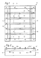
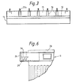
- a filter sub-assembly for installation in the air flow path defined by the housing of a filter assembly comprises a filter frame a part 10 of which is shown in Figures 1 to 3 and six filter units 9.
- the filter frame comprises a support frame 10 (see Figures 1 to 3) and a seal frame 11 (see Figures 7 and 8) locatable relative to the support frame 10.
- the support frame 10 is of a generally rectangular form and comprises four edge members 12,13,14,15 which are adapted for installation in fluid tight manner against the internal walls of a filter housing (not shown).
- the support frame comprises five cross members 16 arranged uniformly spaced apart to extend parallel with one another from one longer edge member 12 to the opposite edge member 14, the cross members thereby co-operating with the shorter edge members 13,15 to define six filter unit apertures 17 each of a rectangular shape.
- the frame additionally comprises a pair of parallel support bars 18 which extend between the shorter edge members 13,15; these bars 18 are spaced apart by a distance which corresponds with the width of the main body portion of a filter unit 9.
- a plurality of bolts 19 are secured to the edge members 12 to 15 at uniformly spaced positions, with the bolt heads 20a being welded to underside surfaces of the edge members and the screw-threaded portions 20b extending upwards through the members.
- the cross members 16 are each similarly provided with a bolt 21 at their mid-length positions. The purpose of the bolts 19 and 21 is described below.
- the filter units 9 each comprise a header portion 22 from which depends an integrally formed body portion 23.
- the body portion comprises a plurality of parallel passages 24 each sealed at a lower end 25 of the body portion and open at the upper, header end portion.
- the header and body portions are formed integrally into a substantially rigid and self-supporting structure by moulding powdered plastics material to the required shape and then subjecting it to a sintering operation.
- One such technique for forming a filter unit is described in more detail in the specification of German Patent Specification DE-A-2807159.
- the header portion 22 has a greater dimension than the body portion 23 both as considered in relation to the width of the body portion as illustrated in Figure 4 and the thickness of the body portion as illustrated in Figure 5.
- the width (length) and thickness of the header portion are arranged to be slightly less than the size of the rectangular apertures 17 whereby each filter unit may be inserted into the support frame 10 to lie (below the level of the upper surfaces 12' to 15' of the edge members 12 to 15) with its header portion within a rectangular aperture 17 and with end regions 26 of each header portion resting on the support bars 18.
- each header portion being a surface which faces axially outwardly in a direction opposite that in which the body portion 23 extends from the header portion 22, is machined flat and carries an annular sealing gasket 28 of generally rectangular form having an opening for alignment with the upper ends of the filter passages 24.
- each header portion has a nut 35 moulded integrally therewith and positioned co-axially of a passage which opens at the upper face 27 of the header portion.
- the lower end 25 of the filter unit body portion carries a channel member 30 which serves to locate that end of the filter relative to a location bar (not shown) of a filter housing and thereby restrain excess sideways movement as considered in the plane of Figure 5.
- the filter frame additionally comprises the seal frame 11 in the form of an apertured sealing plate 31 (see Figure 7).
- the plate 31 is formed, in this embodiment, with six rows of circular apertures (not shown), each row being alignable with the filter unit apertures 17 of the support frame, but each of a smaller size corresponding generally to the size of the plurality of openings at the upper ends of the filter unit passages 24.
- the plate 31 additionally is formed with circular holes at positions corresponding to the positions of the bolts 19,21 extending upwards from an upper surface of the seal frame.
- the frame further comprises an annular frame gasket 32 of a shape corresponding to that of the upper surfaces 12' to 15' of the edge members 12 to 15.
- the sealing plate 31 and the gasket 32 each have an overall rectangular shape the dimensions of which are slightly less than those of the support frame 10 so that they may readily be positioned in and removed from a filter housing.
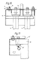
- FIGS 7 and 8 show the filter sub-assembly in an exploded form corresponding to an interim stage in construction of the assembly. These Figures show a filter unit 9 resting upon one of the pair of support bars 18, and it will be seen that in this condition the top of the sealing gasket 28 does not protrude above the top face of the support frame 10.
- the aforedescribed frame gasket 32 is arranged to be interposed between the support frame 10 and seal frame 11 and is compressed therebetween (see Figures 9 and 10) by means of nuts 33 which are screwed onto the bolts 19,21.
- the filter units are sealed to the sealing plate by the interposed gaskets 28 and that the sealing plate is sealed to the support frame by the frame gasket 32.
- the support frame is arranged in sealing contact with a filter housing and thus all gas flow through the housing must pass through the filtration material of the filter units 9.
- the inspection and/or replacement of a or each filter unit can be effected readily from the upper, clean side of the filter sub-assembly. This is achieved by first unscrewing the bolts 34 to allow the filter unit header portion to lower down onto and be supported by the support bars 18. The nuts 33 are then undone to allow the seal plate 11 and frame gasket 32 to be removed, whereupon the or each filter unit can then be lifted out of the assembly. A replacement or inspected filter unit is then positioned on the supports bars 18 and the aforedescribed assembly procedure is repeated to bring the filter units into sealing contact with the seal plate.
- seal plate and header end portions 22 of the filter units be clamped directly to one another.
- the seal plate may be clamped, for example by means of clamp nuts and bolts, to the support frame 10 to cause compression of the interposed header gaskets 28.
- the upper surfaces 12' to 15' of the edge members are positioned to be at a level appropriate relative to the level of the header gaskets 28 to ensure that the frame gasket 32 and header gaskets 28 are simultaneously compressed to the required extent as the seal plate is clamped down onto the support frame.
- each header end portion 22 be formed with integral nuts 29.
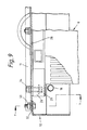
- Each end region 26' may be provided with a metal reinforcing shoe 60 and a clamp nut 29' may be welded or otherwise secured to that shoe without the need for integral moulding of the nut within the filter unit.
Landscapes
- Chemical & Material Sciences (AREA)
- Chemical Kinetics & Catalysis (AREA)
- Physics & Mathematics (AREA)
- Geometry (AREA)
- Filtering Of Dispersed Particles In Gases (AREA)
Applications Claiming Priority (2)
| Application Number | Priority Date | Filing Date | Title |
|---|---|---|---|
| GB8929176 | 1989-12-23 | ||
| GB898929176A GB8929176D0 (en) | 1989-12-23 | 1989-12-23 | Improvements in and relating to removable filter units |
Publications (1)
| Publication Number | Publication Date |
|---|---|
| EP0435545A1 true EP0435545A1 (de) | 1991-07-03 |
Family
ID=10668499
Family Applications (1)
| Application Number | Title | Priority Date | Filing Date |
|---|---|---|---|
| EP90313818A Withdrawn EP0435545A1 (de) | 1989-12-23 | 1990-12-18 | Verbesserungen bezüglich auswechselbarer Filtereinheiten |
Country Status (5)
| Country | Link |
|---|---|
| US (1) | US5123944A (de) |
| EP (1) | EP0435545A1 (de) |
| JP (1) | JPH04156910A (de) |
| AU (1) | AU639515B2 (de) |
| GB (2) | GB8929176D0 (de) |
Cited By (1)
| Publication number | Priority date | Publication date | Assignee | Title |
|---|---|---|---|---|
| CN102489090A (zh) * | 2011-12-14 | 2012-06-13 | 无锡红旗除尘设备有限公司 | 除尘器提升阀装置 |
Families Citing this family (4)
| Publication number | Priority date | Publication date | Assignee | Title |
|---|---|---|---|---|
| US5599364A (en) * | 1994-11-14 | 1997-02-04 | Hawkins; Charles | Filter locking/support system for dust collectors |
| US5752999A (en) * | 1996-02-20 | 1998-05-19 | Westinghouse Electric Corporation | Hot gas filtering apparatus |
| US6146528A (en) * | 1999-03-09 | 2000-11-14 | Caughman, Jr.; Carl Russell | Sludge filtration system including selectively slidably removable filter assemblies and method |
| CN104797444B (zh) * | 2012-09-20 | 2017-04-12 | 冷王公司 | 用于运输舱中的加热、通风和空气调节单元的空气过滤系统和方法 |
Citations (3)
| Publication number | Priority date | Publication date | Assignee | Title |
|---|---|---|---|---|
| DE8629362U1 (de) * | 1986-11-04 | 1987-01-02 | Sietam Gesellschaft für Fördertechnik und Apparatebau mbH, 6806 Viernheim | Filteraggregat für den Untertagebetrieb im Bergbau |
| EP0257793A1 (de) * | 1986-07-22 | 1988-03-02 | INDUSTRIAL FILTER & PUMP MFG.CO. | Filteranlage |
| WO1988003834A1 (en) * | 1986-11-18 | 1988-06-02 | Westinghouse Electric Corporation | Filter unit for use at high temperatures |
Family Cites Families (6)
| Publication number | Priority date | Publication date | Assignee | Title |
|---|---|---|---|---|
| US1747131A (en) * | 1927-04-05 | 1930-02-11 | New Haven Sand Blast Company | Dust arrester |
| US2640560A (en) * | 1951-12-29 | 1953-06-02 | Mine Safety Appliances Co | Dust filtering apparatus |
| DE1228898B (de) * | 1956-02-21 | 1966-11-17 | Deutsche Edelstahlwerke Ag | Filterkoerper aus poroesem Sintermetall zum Abscheiden feinster Schwebteilchen |
| GB931062A (en) * | 1960-10-05 | 1963-07-10 | Doulton & Co Ltd | Filter elements |
| GB1039317A (en) * | 1963-06-15 | 1966-08-17 | Walter Mayer | Filtration equipment |
| GB2137110A (en) * | 1983-03-29 | 1984-10-03 | Swinney Eng | Filter Element Mounting |
-
1989
- 1989-12-23 GB GB898929176A patent/GB8929176D0/en active Pending
-
1990
- 1990-12-18 US US07/629,605 patent/US5123944A/en not_active Expired - Fee Related
- 1990-12-18 EP EP90313818A patent/EP0435545A1/de not_active Withdrawn
- 1990-12-18 GB GB9027345A patent/GB2239195B/en not_active Expired - Fee Related
- 1990-12-20 AU AU68277/90A patent/AU639515B2/en not_active Ceased
- 1990-12-21 JP JP2405142A patent/JPH04156910A/ja active Pending
Patent Citations (3)
| Publication number | Priority date | Publication date | Assignee | Title |
|---|---|---|---|---|
| EP0257793A1 (de) * | 1986-07-22 | 1988-03-02 | INDUSTRIAL FILTER & PUMP MFG.CO. | Filteranlage |
| DE8629362U1 (de) * | 1986-11-04 | 1987-01-02 | Sietam Gesellschaft für Fördertechnik und Apparatebau mbH, 6806 Viernheim | Filteraggregat für den Untertagebetrieb im Bergbau |
| WO1988003834A1 (en) * | 1986-11-18 | 1988-06-02 | Westinghouse Electric Corporation | Filter unit for use at high temperatures |
Cited By (2)
| Publication number | Priority date | Publication date | Assignee | Title |
|---|---|---|---|---|
| CN102489090A (zh) * | 2011-12-14 | 2012-06-13 | 无锡红旗除尘设备有限公司 | 除尘器提升阀装置 |
| CN102489090B (zh) * | 2011-12-14 | 2014-06-25 | 无锡红旗除尘设备有限公司 | 除尘器提升阀装置 |
Also Published As
| Publication number | Publication date |
|---|---|
| GB2239195A (en) | 1991-06-26 |
| GB8929176D0 (en) | 1990-02-28 |
| AU6827790A (en) | 1991-06-27 |
| GB9027345D0 (en) | 1991-02-06 |
| AU639515B2 (en) | 1993-07-29 |
| GB2239195B (en) | 1993-08-04 |
| US5123944A (en) | 1992-06-23 |
| JPH04156910A (ja) | 1992-05-29 |
Similar Documents
| Publication | Publication Date | Title |
|---|---|---|
| US3747772A (en) | Filter | |
| CA2097447C (en) | Filter system, especially for filtering the air intake of an internal combustion engine | |
| EP3525911B1 (de) | Rundfilterelement, insbesondere zur gasfiltration | |
| JPH0847613A (ja) | 集塵装置におけるフィルタエレメントの支持構造 | |
| EP4163004B1 (de) | Vorrichtung zur abtrennung eines stoffes aus einem gas | |
| CN109126299B (zh) | 扁平过滤器元件,具体地用于气体过滤 | |
| US5123944A (en) | Removable filter units | |
| US4023944A (en) | Filter unit | |
| JP3774784B2 (ja) | クリーンルームのフィルタ交換用補助装置 | |
| US4124362A (en) | Snap together header and cell side assembly | |
| EP1848948A1 (de) | Wärmetauscher | |
| EP0687492B1 (de) | Membranfilterplatte für eine Filterpresse | |
| DE2627117A1 (de) | Austragseinrichtung fuer filtermaterial | |
| US5049172A (en) | Blow out resistant filter | |
| US11280299B2 (en) | Filter element for an engine air filter assembly having a nonwoven pre-filter and related method | |
| DE3516941C2 (de) | ||
| DE4344269A1 (de) | Luftreiniger für Fahrzeuge | |
| JP2892323B2 (ja) | フィルタープレス用濾過板 | |
| DE4031441C2 (de) | ||
| WO1995015805A1 (en) | A septum for a filter, and a filter fitted therewith | |
| DE3711734C1 (en) | Filtration apparatus for the filtration of liquids, in particular by means of reduced pressure or overpressure | |
| GB2218009A (en) | Fluid filter | |
| WO2024251487A1 (de) | Filtersystem mit wenigstens zwei filterelementen | |
| JPH0217609Y2 (de) | ||
| DE3431401C2 (de) |
Legal Events
| Date | Code | Title | Description |
|---|---|---|---|
| PUAI | Public reference made under article 153(3) epc to a published international application that has entered the european phase |
Free format text: ORIGINAL CODE: 0009012 |
|
| AK | Designated contracting states |
Kind code of ref document: A1 Designated state(s): AT CH DE DK ES FR LI NL SE |
|
| 17P | Request for examination filed |
Effective date: 19911223 |
|
| 17Q | First examination report despatched |
Effective date: 19930419 |
|
| STAA | Information on the status of an ep patent application or granted ep patent |
Free format text: STATUS: THE APPLICATION HAS BEEN WITHDRAWN |
|
| 18W | Application withdrawn |
Withdrawal date: 19940125 |
|
| R18W | Application withdrawn (corrected) |
Effective date: 19940125 |