EP0435663B1 - Magnetisches Aufzeichnungs-/Wiedergabegerät für TCI-Signale - Google Patents
Magnetisches Aufzeichnungs-/Wiedergabegerät für TCI-Signale Download PDFInfo
- Publication number
- EP0435663B1 EP0435663B1 EP90314296A EP90314296A EP0435663B1 EP 0435663 B1 EP0435663 B1 EP 0435663B1 EP 90314296 A EP90314296 A EP 90314296A EP 90314296 A EP90314296 A EP 90314296A EP 0435663 B1 EP0435663 B1 EP 0435663B1
- Authority
- EP
- European Patent Office
- Prior art keywords
- signal
- tci
- chrominance
- recording
- reproduced
- Prior art date
- Legal status (The legal status is an assumption and is not a legal conclusion. Google has not performed a legal analysis and makes no representation as to the accuracy of the status listed.)
- Expired - Lifetime
Links
- 108010076504 Protein Sorting Signals Proteins 0.000 claims description 11
- 238000000034 method Methods 0.000 claims description 11
- 238000012937 correction Methods 0.000 claims description 5
- 230000003111 delayed effect Effects 0.000 claims description 2
- 230000010354 integration Effects 0.000 claims description 2
- 230000008878 coupling Effects 0.000 claims 1
- 238000010168 coupling process Methods 0.000 claims 1
- 238000005859 coupling reaction Methods 0.000 claims 1
- 238000010586 diagram Methods 0.000 description 10
- 238000012545 processing Methods 0.000 description 6
- 230000007257 malfunction Effects 0.000 description 2
- 239000000969 carrier Substances 0.000 description 1
- 238000006243 chemical reaction Methods 0.000 description 1
- 230000006835 compression Effects 0.000 description 1
- 238000007906 compression Methods 0.000 description 1
- 238000001514 detection method Methods 0.000 description 1
- 238000011161 development Methods 0.000 description 1
- 238000007429 general method Methods 0.000 description 1
- 230000007274 generation of a signal involved in cell-cell signaling Effects 0.000 description 1
- 238000003780 insertion Methods 0.000 description 1
- 230000037431 insertion Effects 0.000 description 1
- 230000004044 response Effects 0.000 description 1
Images




Classifications
-
- H—ELECTRICITY
- H04—ELECTRIC COMMUNICATION TECHNIQUE
- H04N—PICTORIAL COMMUNICATION, e.g. TELEVISION
- H04N9/00—Details of colour television systems
- H04N9/79—Processing of colour television signals in connection with recording
- H04N9/80—Transformation of the television signal for recording, e.g. modulation, frequency changing; Inverse transformation for playback
- H04N9/81—Transformation of the television signal for recording, e.g. modulation, frequency changing; Inverse transformation for playback the individual colour picture signal components being recorded sequentially only
-
- H—ELECTRICITY
- H04—ELECTRIC COMMUNICATION TECHNIQUE
- H04N—PICTORIAL COMMUNICATION, e.g. TELEVISION
- H04N9/00—Details of colour television systems
- H04N9/79—Processing of colour television signals in connection with recording
- H04N9/87—Regeneration of colour television signals
- H04N9/873—Regeneration of colour television signals for restoring the colour component sequence of the reproduced chrominance signal
-
- H—ELECTRICITY
- H04—ELECTRIC COMMUNICATION TECHNIQUE
- H04N—PICTORIAL COMMUNICATION, e.g. TELEVISION
- H04N9/00—Details of colour television systems
- H04N9/79—Processing of colour television signals in connection with recording
- H04N9/87—Regeneration of colour television signals
- H04N9/89—Time-base error compensation
- H04N9/896—Time-base error compensation using a digital memory with independent write-in and read-out clock generators
Definitions
- the present invention relates generally to magnetic recording/reproduction devices, and more particularly to a magnetic recording/reproduction device such as a video tape recorder (referred to as a VTR hereinafter) that records and reproduces TCI (Time Compressed Integration) signals obtained by time base compressing each of the luminance signal and the chrominance signal and time-divisionally multiplexing both.
- a magnetic recording/reproduction device such as a video tape recorder (referred to as a VTR hereinafter) that records and reproduces TCI (Time Compressed Integration) signals obtained by time base compressing each of the luminance signal and the chrominance signal and time-divisionally multiplexing both.
- TCI Time Compressed Integration
- VTR employing a TCI signal as the recording signal format.
- This TCI signal is obtained by time base processing a luminance signal as well as a color line sequential signal obtained by applying line sequential processing to two chrominance signals (for example, color difference signals) C1 and C2, and time-divisionally multiplexing these signals in the same recording line (one horizontal scanning period).
- chrominance signals for example, color difference signals
- Such VTRs are disclosed in the technical reports of the Institute of Television Engineers of Japan, Vol. 13 No. 50, pp. 1-6, VIR 89-12, Vol. 13, No. 50, pp. 7-12, VIR 89-13, for example.
- Fig. 1 is a block diagram showing a TBC (Time Base Corrector) circuit as an example of a reproduction processing system of a VTR for the above mentioned TCI signal.
- TBC Time Base Corrector
- FM signals reproduced by magnetic heads 22a and 22b from respective tracks on a magnetic tape 21 are amplified at the corresponding reproduction amplifiers 23a and 23b, and provided to a switching circuit 24 to be converted into a continuous reproduced TCI signal.
- the reproduced TCI signal is provided to an FM demodulator 14 to be FM demodulated.
- the reproduced TCI signal provided from FM demodulator 14 is applied to an A/D converter 17, a writing clock generator 15, and a synchronizing signal separating circuit 16.
- Writing clock generator 15 generates a write clock signal Wck phase-synchronized with the reproduced TCI signal, and provides the same to A/D converter 17 and to a TBC line memory 18.
- the synchronizing signal separating circuit 16 separates the horizontal synchronizing signal from the reproduced TCI signal and provides the same to TBC line memory 18.
- A/D converter 17 is responsive to writing clock signal Wck from writing clock generator 15 to convert the reproduced TCI signal into a digital signal, and provides the same to TBC line memory 18 for time base correction. This digital TCI signal is written into TBC line memory 18 for each 1 horizontal line at the timing of writing clock signal Wck.
- TBC line memory 18 digital data corresponding to the reproduced TCI signal is read out from TBC line memory 18 according to the timing of a read out clock signal Rck provided from a reference signal generator 20, whereby time base correction of the reproduced TCI signal is carried out.
- TBC line memory 18 is implemented so as to allow asynchronous access for writing and reading.
- the reproduced TCI signal read out from TBC line memory 18 is provided to a TCI decoder 19.
- TCI decoder 19 carries out time base process to the reproduced TCI signal according to the timing signal provided from reference signal generator 20 to restore a luminance signal Y and chrominance signals C1 and C2.
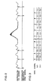
- Fig. 2 is a waveform chart of a reproduced TCI signal in variable speed reproduction.
- Fig. 3 is a diagram schematically showing the color line sequence manner of a TCI signal, in which (a) shows the chrominance signal sequence of the TCI signal actually applied to TCI decoder 19, and (b) shows the proper chrominance signal processing sequence in TCI decoder 19. If the horizontal synchronizing signal is missing in the reproduced TCI signal, there is discrepancy between the chrominance signal sequence (a) actually applied to TCI decoder 19 and the chrominance signal sequence (b) that should have been applied to TCI decoder 19, as shown in Fig. 3.
- hue error is generated on the monitor in case of some malfunction in line management of the TBC circuit even at the time of normal reproduction.
- a method is disclosed in Japanese Patent Laying-Open JP-A-60214693 to identify in advance the chrominance signal sequence of the TCI signal at the time of recording.
- this method requires a separate creation of a color discrimination signal and insertion into the TCI signal, not allowing to increase sufficiently the time width of the color discrimination signal. Insufficient time width of the color discrimination signal will make it difficult to detect the color discrimination signal at the time of reproduction of the TCI signal, with the possibility of erroneous determination of chrominance signal sequence.
- US-A-4630131 discloses a recording signal generation system for a color video signal in which a time-compressed line sequential color signal is time division multiplexed with a luminance signal, the two line sequential compressed color signals occupying alternate successive horizontal blanking periods.
- the two kinds of color signals are identified by respective kinds of burst pilot signals each having a duration equal to the horizontal blanking period and superposed on but separable from the color signals.
- US-A-3717725 discloses a non-compression technique for recording a television signal in which a line sequential chrominance signal and a luminance signal are modulated on separate carriers having respectively, relatively low and high carrier frequencies. Synchronizing pulses modulated by a color index pulse are added to the luminance signal prior to modulation and subsequent mixing with the modulated line sequential chrominance signal.
- the present invention aims to allow the stable reproduction of a chrominance signal in a magnetic recording/reproduction device adopting a TCI signal as the recording signal format.
- the present invention also aims to prevent the generation of hue error particularly at the time of variable speed reproduction, in a magnetic recording/ reproduction device adopting a TCI signal as the recording signal format.
- a magnetic recording/reproduction device for recording and reproducing a TCI signal obtained by time-divisionally multiplexing a luminance signal and line sequential processed first and second chrominance signals, said TCI signal including in successive horizontal periods alternately a first recording line having said luminance signal and said first chrominance signal time-divisionally multiplexed, and a second recording line having said luminance signal and said second chrominance signal time-divisionally multiplexed
- said magnetic recording/ reproduction device comprising: means for FM recording said TCI signal on a magnetic recording medium, means for FM-reproducing said TCI signal from said magnetic recording medium, and decode means for decoding said reproduced TCI signal to restore said luminance signal and said first and second chrominance signals, characterised by synchronizing signal adding means for adding first and second horizontal synchronizing signals having respective different time widths to the respective first and second recording lines of said TCI signal at the time of recording, synchronizing signal separating means for separating said first and second horizontal
- the main advantage of the present invention lies in that it is possible to correct the discrepancy between the chrominance signal sequence to be decoded and the proper sequence at the time of reproduction by setting the time width of the horizontal synchronizing signal of the TCI signal according to the type of the chrominance signal of the corresponding recording line at the time of recording, preventing the generation of hue error.
- Another advantage of the present invention lies in that erroneous detection of color determination signal is prevented at the time of special reproduction due to the fact that determination of chrominance signals is carried out using the time width of the horizontal synchronizing signal of the TCI signal.
- Fig. 1 is a block diagram showing an example of a reproduction process system of a conventional VTR for TCI signals.
- Fig. 2 is a waveform chart showing a reproduced TCI signal at the time of variable speed reproduction.
- Fig. 3 is a diagram showing schematically the color line sequence of a TCI signal.
- Fig. 4 is a block diagram showing the recording system of a VTR of an embodiment of the present invention.
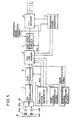
- Fig. 5 is a block diagram showing the reproduction system of a VTR of an embodiment of the present invention.
- Fig. 6 is a waveform chart describing the method of creating a TCI signal.
- Figs. 7A, 7B and 7C are waveform charts each showing the horizontal synchronizing signal of a TCI signal according to the present invention.
- Fig. 8 is a waveform chart showing schematically the structure of a TCI signal.
- Fig. 9 is a block diagram showing in detail a hue error preventing circuit of Fig. 5.
- Fig. 4 is a block diagram showing a recording system of a VTR of an embodiment of the present invention.
- Fig. 6 is a waveform chart showing a general method of creating a TCI signal. Referring to Figs. 4 and 6, a luminance signal and two chrominance signal components C1 and C2 forming a video signal are converted into digital signals by A/D converters 25, 26 and 27, respectively, according to the timing signal from a timing generator 43.
- the digital chrominance signal component C1 (Fig.
- TCI encoder 32 chrominance signal C1 and luminance signal Y are time-divisionally multiplexed at a horizontal period, and chrominance signal C2 and luminance signal Y are time-divisionally multiplexed at the next horizontal period (Fig. 6(d)).
- the output of TCI encoders 32 is converted into an analog signal by D/A converter 33 and provided to FM demodulator 34.
- TCI encoder 32 and D/A converter 33 are controlled by the timing signal from timing generator 43.
- the output of D/A converter 33 is FM demodulated by FM demodulator 34 to be FM recorded on respective tracks of a magnetic tape 42 through magnetic heads 37 and 38 after current control by recording amplifiers 35 and 36.
- information regarding the chrominance signal in the corresponding recording line i.e. the information concerning whether chrominance signal component multiplexed in the corresponding line is either C1 or C2 is indicated depending upon whether the time width of the negative horizontal synchronizing signal in the TCI signal is broad or narrow. Therefore, two types of negative waveform signals are used as the horizontal synchronizing signal in the TCI signal, as shown in Fig. 7A. (I) of Fig.
- FIG. 7A shows a waveform of a horizontal synchronizing signal when the chrominance signal multiplexed in the corresponding line is C1
- (II) shows a waveform of a horizontal synchronizing signal when the chrominance signal multiplexed in the corresponding line is C2.
- (I) of Fig. 7A may show chrominance signal component C2
- (II) may show chrominance signal component C1 conversely.
- the combination of the waveforms of the horizontal synchronizing signal for identifying two chrominance signal components C1 and C2 is not limited to that shown in Fig. 7A, and the combinations shown in Figs. 7B and 7C may also be used.
- the horizontal synchronizing signal having a different time width is inserted at the head of the chrominance signal component of the corresponding recording line, by synchronizing signal adding circuit 31.
- a TCI signal encoded as shown in Fig. 8 is recorded on magnetic tape 42.
- Fig. 5 is a block diagram showing a TBC circuit of the reproduction system of a VTR according to an embodiment of the present invention.
- FM signals of two tracks reproduced from magnetic tape 42 by magnetic heads 44a and 44b are amplified by the corresponding reproduction amplifiers 45a and 45b, where the same are applied to switching circuit 46 to be converted into a continuous reproduced TCI signal.
- the reproduced TCI signal is applied to a FM demodulator 1 to be FM demodulated.
- the reproduced TCI signal provided from FM demodulator 1 is applied to an A/D converter 5, a writing clock generator 2 and a synchronizing signal separating circuit 3.
- the writing clock generator 2 generates a writing clock signal Wck phase-synchronized with the reproduced TCI signal and provides the same to A/D converter 5 and a TBC line memory 6.
- the synchronizing signal separating circuit 3 separates the horizontal synchronizing signal from the reproduced TCI signal, and provides the same to TBC line memory 6 and a chrominance signal determining circuit 4.
- Chrominance signal determining circuit 4 detects the time width of the horizontal synchronizing signal separated by synchronizing signal separating circuit 3 to identify the chrominance signal component (C1 or C2) multiplexed in the corresponding reproduced line (horizontal scanning period).
- This circuit 4 generates a digital data (color identification signal) indicating the result as a binary of ⁇ 1 ⁇ or ⁇ 0 ⁇ , whereby the same is provided to TBC line memory 6.
- A/D converter 5 is responsive to writing clock signal Wck from writing clock generator 2 to convert the reproduced TCI signal into a digital signal, and provides the same to TBC line memory 6 for time base correction.
- the aforementioned color identification signal is inserted in the horizontal blanking portion of the provided TCI signal.
- This TCI signal is written into TBC line memory 6 for every 1 horizontal line at the timing of writing clock signal Wck.
- Data in the region excluding the region associated with chrominance signals and luminance signal are not necessary for further signal processing regarding the reproduced TCI signal after the A/D conversion by A/D converter 5. Therefore, it is possible to insert color identification signals, as mentioned above, in regions other than the above mentioned region of the data.
- TBC line memory 6 is implemented to carry out writing and reading asynchronously.
- Fig. 9 is a block diagram showing the hue error preventing circuit 7 of Fig. 5.
- the TCI signal provided from TBC line memory 6 is applied to sequence detecting circuit 12, where the chrominance signal component sequence of the reproduced TCI signal is determined according to the color identification signal inserted in the horizontal blanking portion.
- the signal showing the proper chrominance signal processing sequence of TCI decoder 8 is provided from reference signal generating circuit 9 to hue error preventing circuit 7, whereby the actually detected chrominance signal sequence and the proper chrominance signal sequence are compared in sequence comparing circuit 13. If there is discrepancy between these sequences as shown in Fig.
- a switch 10 connects to contact a side, whereby the reproduced TCI signal is delayed by delay circuit 11 for 1 horizontal scanning period to make both sequences coincide. Then the reproduced TCI signal is provided to TCI decoder 8. When there is no discrepancy between these sequences, switch 10 is connected to the contact b side, whereby the reproduced TCI signal provided from TBC line memory 6 is directly applied to TCI decoder 8.
- TCI decoder 8 is responsive to the timing signal provided from reference signal generator 9 to carry out time base process to the reproduced TCI signal for restoring luminance signal Y and chrominance signals C1 and C2.
Landscapes
- Engineering & Computer Science (AREA)
- Multimedia (AREA)
- Signal Processing (AREA)
- Television Signal Processing For Recording (AREA)
Claims (6)
- Magnetisches Aufzeichnungs-/Wiedergabegerät für das Aufzeichnen und Wiedergeben eines zeitkomprimierten Integrationssignals (TCI-Signal), das durch Zeitmultiplexbildung aus einem Luminanzsignal und zeilensequentiell verarbeiteten ersten und zweiten Chrominanzsignalen erhalten wird, wobei das TCI-Signal in aufeinanderfolgenden horizontalen Perioden abwechselnd eine erste Aufzeichnungszeile mit dem zeitlich ineinander geschachtelten Luminanzsignal und ersten Chrominanzsignal und eine zweite Aufzeichnungszeile mit dem zeitlich ineinander geschachtelten Luminanzsignal und zweiten Chrominanzsignal enthält, mitMitteln (34-48) zum FM-Aufzeichnen des TCI-Signals auf einem magnetischen Aufzeichnungsmedium,Mitteln (1,44-46) zum FM-Wiedergeben des TCI-Signals vom magnetischen Aufzeichnungsmedium, undDekodiermitteln (8) zum Dekodieren des wiedergegebenen TCI-Signals um das Luminanzsignal und das erste und zweite Chrominanzsignal wiederherzustellen,gekennzeichnet durchSynchronisationssignal-Addiermittel (31) zum Hinzufügen erster und zweiter Horizontal-Synchronisationssignale, die jeweils zu den jeweiligen ersten und zweiten Aufzeichnungszeilen des TCI-Signals zur Zeit der Aufzeichnung verschiedene Zeitbreiten haben,Synchronisationssignal-Trennmittel (3) zum Abtrennen des ersten und zweiten Horizontal-Synchronisationssignals vom wiedergegebenen TCI-Signal,Mittel (4) zum Bestimmen auf der Basis der Zeitbreite des getrennten Horizontal-Synchronisationssignals, ob das in der Aufzeichnungszeile des von den FM-Wiedergabemitteln wiedergegebenen TCI-Signals geschachtelte Chrominanzsignal das erste Chrominanzsignal oder das zweite Chrominanzsignal ist, undMittel (7) zum Steuern der Dekodierfolge des ersten und zweiten Chrominanzsignals durch die Dekodiermittel abhängig von dem Resultat der Bestimmung der Bestimmittel (4).
- Aufzeichnungs-/Wiedergabegerät nach Anspruch 1, das ferner TBC-Zeilenspeichermittel (6) enthält, die zwischen die FM-Wiedergabemittel (1,44-46) und die Dekodiermittel (8) geschaltet sind, um am wiedergegebenen TCI-Signal eine Zeitbasiskorrektur anzubringen.
- Aufzeichnungs-/Wiedergabegerät nach Anspruch 2, bei demdie Bestimmittel (4) ein Farbidentifikationssignal erzeugen, das das Resultat der Bestimmung des Chrominanzsignals anzeigt, um dieses an die TBC-Zeilenspeichermittel zu liefern, unddie TBC-Zeilenspeichermittel das Farbidentifikationssignal in einen anderen Bereich als den Bereich des Luminanzsignals und des Chrominanzsignals des wiedergegebenen TCI-Signals einfügen.
- Aufzeichnungs-/Wiedergabegerät nach Anspruch 3, das ferner Mittel (9) zum Erzeugen eines Signals enthält, das die richtige Folge der Chrominanzsignalverarbeitung durch die Dekodiermittel zeigt.
- Aufzeichnungs-/Wiedergabegerät nach Anspruch 4, bei dem die Folgensteuermittel (7) enthalten:Mittel (12) zum Bestimmen der Chrominanzsignalfolge des wiedergegebenen TCI-Signals, das von den TBC-Zeilenspeichermitteln geliefert wird, abhängig vom Farbidentifikationssignal, das in das wiedergegebene TCI-Signal eingefügt ist,Mittel (13) zum Vergleichen der bestimmten Chrominanzsignalfolge mit der richtigen Folge der Chrominanzsignalverarbeitung, undMittel (10,11) um abhängig vom Resultat des Vergleichs durch die Vergleichsmittel die bestimmte Chrominanzsignalfolge zeitlich mit der richtigen Folge der Chrominanzsignalverarbeitung zusammenfallend zu machen.
- Aufzeichnungs-/Wiedergabegerät nach Anspruch 5, bei dem die Mittel zum zeitlich zusammenfallend Machen eine Verzögerungsschaltung (11) zum Verzögern des wiedergegebenen TCI-Signals um eine horizontale Abtastperiode und einen Schalter (10) zum selektiven Zuführen des vom TBC-Zeilenspeicher (6) gelieferten wiedergegebenen TCI-Signals oder des durch die Verzögerungsschaltung verzögerten wiedergegebenen TCI-Signals an die Dekodiermittel (8) enthalten.
Applications Claiming Priority (2)
| Application Number | Priority Date | Filing Date | Title |
|---|---|---|---|
| JP1341026A JPH03198596A (ja) | 1989-12-27 | 1989-12-27 | 磁気記録再生装置 |
| JP341026/89 | 1989-12-27 |
Publications (3)
| Publication Number | Publication Date |
|---|---|
| EP0435663A2 EP0435663A2 (de) | 1991-07-03 |
| EP0435663A3 EP0435663A3 (en) | 1992-07-15 |
| EP0435663B1 true EP0435663B1 (de) | 1996-08-14 |
Family
ID=18342537
Family Applications (1)
| Application Number | Title | Priority Date | Filing Date |
|---|---|---|---|
| EP90314296A Expired - Lifetime EP0435663B1 (de) | 1989-12-27 | 1990-12-24 | Magnetisches Aufzeichnungs-/Wiedergabegerät für TCI-Signale |
Country Status (4)
| Country | Link |
|---|---|
| US (1) | US5258851A (de) |
| EP (1) | EP0435663B1 (de) |
| JP (1) | JPH03198596A (de) |
| DE (1) | DE69028085T2 (de) |
Families Citing this family (3)
| Publication number | Priority date | Publication date | Assignee | Title |
|---|---|---|---|---|
| US5293248A (en) * | 1991-05-06 | 1994-03-08 | U.S. Philips Corporation | System and apparatus for recording and reproducing and extended definition video signal in/from a track on a magnetic carrier |
| US5594553A (en) * | 1992-09-04 | 1997-01-14 | Asahi Kogaku Kogyo Kabushiki Kaisha | Video signal recording and reproducing apparatus using signal modification to remove jitter |
| US8015745B2 (en) * | 2007-08-21 | 2011-09-13 | Brian Spencer Westover | Trapped air strike indicator and fly |
Family Cites Families (10)
| Publication number | Priority date | Publication date | Assignee | Title |
|---|---|---|---|---|
| GB1188392A (en) * | 1966-07-19 | 1970-04-15 | Sony Corp | Television Signal Recording System |
| AU523619B2 (en) * | 1978-04-07 | 1982-08-05 | Sony Corporation | Video signal processing system |
| JPS59146288A (ja) * | 1983-02-09 | 1984-08-22 | Victor Co Of Japan Ltd | カラ−映像信号の記録信号の生成方式 |
| JPS60127893A (ja) * | 1983-12-15 | 1985-07-08 | Sony Corp | カラ−テレビジヨン信号伝送方式 |
| US4758898A (en) * | 1984-07-30 | 1988-07-19 | Sanyo Electric Co., Ltd. | Video signal recording and reproducing apparatus |
| US4716454A (en) * | 1985-10-17 | 1987-12-29 | Ampex Corporation | Chroma phase word encode/decode in a video processing system |
| KR900007470B1 (ko) * | 1986-02-18 | 1990-10-10 | 마쯔시다덴기산교 가부시기가이샤 | 영상신호의 기록방법 및 기록재생장치 |
| JPS62234478A (ja) * | 1986-04-04 | 1987-10-14 | Matsushita Electric Ind Co Ltd | 映像信号の記録再生装置 |
| US5079637A (en) * | 1988-03-16 | 1992-01-07 | Kabushiki Kaisha Toshiba | Apparatus for reproducing color video signal recorded by TCI signal format |
| NL8801206A (nl) * | 1988-05-09 | 1989-12-01 | Philips Nv | Drop-out kompensatieschakeling. |
-
1989
- 1989-12-27 JP JP1341026A patent/JPH03198596A/ja active Pending
-
1990
- 1990-12-21 US US07/631,686 patent/US5258851A/en not_active Expired - Fee Related
- 1990-12-24 DE DE69028085T patent/DE69028085T2/de not_active Expired - Fee Related
- 1990-12-24 EP EP90314296A patent/EP0435663B1/de not_active Expired - Lifetime
Also Published As
| Publication number | Publication date |
|---|---|
| EP0435663A3 (en) | 1992-07-15 |
| DE69028085D1 (de) | 1996-09-19 |
| DE69028085T2 (de) | 1997-01-30 |
| EP0435663A2 (de) | 1991-07-03 |
| JPH03198596A (ja) | 1991-08-29 |
| US5258851A (en) | 1993-11-02 |
Similar Documents
| Publication | Publication Date | Title |
|---|---|---|
| US5012352A (en) | Digital signal recording apparatus time-division multiplexing video and audio signals | |
| US5404248A (en) | Video data recording/reproducing apparatus with efficient error correction | |
| EP0151538B1 (de) | Videorekorder | |
| EP0168834B1 (de) | Verfahren und Gerät zum Aufzeichnen und Wiedergeben von Videosignalen | |
| GB2086691A (en) | Signal processing method for digital signals possibly containing errors | |
| US5101274A (en) | Digital signal recording apparatus time-division multiplexing video and audio signals | |
| EP0404383A2 (de) | Vorrichtung zum Aufnehmen und Wiedergeben von Videosignalen von Bildern mit hoher Auflösung | |
| US5682457A (en) | Method and apparatus for recording HDTV signals having a wide bandwidth on a narrow bandwidth tape | |
| GB2061668A (en) | Slow down processor for video disc mastering | |
| EP0435663B1 (de) | Magnetisches Aufzeichnungs-/Wiedergabegerät für TCI-Signale | |
| EP0465103B1 (de) | Videoband-Wiedergabegerät | |
| EP1046289B1 (de) | Aufnahmevorrichtung zur aufnahme eines digitalen informationssignals auf einem aufnahmeträger | |
| US5198940A (en) | Image signal recording system | |
| EP0461880A2 (de) | Videobandaufzeichnungsgerät | |
| EP0098727A2 (de) | Aufzeichnungs- und Wiedergabesysteme mit Schrägspurabtastung | |
| US5148290A (en) | Video signal recording/reproduction device having dropout compensation function | |
| US5940575A (en) | Video signal recording apparatus | |
| US4807050A (en) | Video signal recording/reproducing apparatus | |
| CA1152632A (en) | Digital process for controlling the correct reproduction of a composite television signal and a device for implementing said process | |
| EP0325256B1 (de) | Gerät zum Wiedergeben von digitalen Videosignalen | |
| JP2569469B2 (ja) | 磁気記録再生装置 | |
| US6134074A (en) | Reproducing apparatus having tracking control in accordance with track number information | |
| JP2792627B2 (ja) | デイジタル信号記録再生装置 | |
| US6671455B1 (en) | Magnetic recording apparatus and method therefor, and magnetic recording and reproduction apparatus and method therefor | |
| JPH0232834B2 (de) |
Legal Events
| Date | Code | Title | Description |
|---|---|---|---|
| PUAI | Public reference made under article 153(3) epc to a published international application that has entered the european phase |
Free format text: ORIGINAL CODE: 0009012 |
|
| 17P | Request for examination filed |
Effective date: 19901231 |
|
| AK | Designated contracting states |
Kind code of ref document: A2 Designated state(s): DE FR GB |
|
| PUAL | Search report despatched |
Free format text: ORIGINAL CODE: 0009013 |
|
| AK | Designated contracting states |
Kind code of ref document: A3 Designated state(s): DE FR GB |
|
| 17Q | First examination report despatched |
Effective date: 19950123 |
|
| GRAH | Despatch of communication of intention to grant a patent |
Free format text: ORIGINAL CODE: EPIDOS IGRA |
|
| GRAH | Despatch of communication of intention to grant a patent |
Free format text: ORIGINAL CODE: EPIDOS IGRA |
|
| GRAA | (expected) grant |
Free format text: ORIGINAL CODE: 0009210 |
|
| AK | Designated contracting states |
Kind code of ref document: B1 Designated state(s): DE FR GB |
|
| REF | Corresponds to: |
Ref document number: 69028085 Country of ref document: DE Date of ref document: 19960919 |
|
| ET | Fr: translation filed | ||
| PLBE | No opposition filed within time limit |
Free format text: ORIGINAL CODE: 0009261 |
|
| STAA | Information on the status of an ep patent application or granted ep patent |
Free format text: STATUS: NO OPPOSITION FILED WITHIN TIME LIMIT |
|
| 26N | No opposition filed | ||
| PGFP | Annual fee paid to national office [announced via postgrant information from national office to epo] |
Ref country code: FR Payment date: 20001212 Year of fee payment: 11 |
|
| PGFP | Annual fee paid to national office [announced via postgrant information from national office to epo] |
Ref country code: DE Payment date: 20001218 Year of fee payment: 11 |
|
| PGFP | Annual fee paid to national office [announced via postgrant information from national office to epo] |
Ref country code: GB Payment date: 20001220 Year of fee payment: 11 |
|
| PG25 | Lapsed in a contracting state [announced via postgrant information from national office to epo] |
Ref country code: GB Free format text: LAPSE BECAUSE OF NON-PAYMENT OF DUE FEES Effective date: 20011224 |
|
| REG | Reference to a national code |
Ref country code: GB Ref legal event code: IF02 |
|
| PG25 | Lapsed in a contracting state [announced via postgrant information from national office to epo] |
Ref country code: DE Free format text: LAPSE BECAUSE OF NON-PAYMENT OF DUE FEES Effective date: 20020702 |
|
| GBPC | Gb: european patent ceased through non-payment of renewal fee |
Effective date: 20011224 |
|
| PG25 | Lapsed in a contracting state [announced via postgrant information from national office to epo] |
Ref country code: FR Free format text: LAPSE BECAUSE OF NON-PAYMENT OF DUE FEES Effective date: 20020830 |
|
| REG | Reference to a national code |
Ref country code: FR Ref legal event code: ST |