EP0435761A1 - Verfahren und Vorrichtung zur Bestimmung der von in unterirdischen, benachbarten, metallischen Strukturen fliessenden kontinuierlichen Strömen verursachten Wechselwirkungen - Google Patents
Verfahren und Vorrichtung zur Bestimmung der von in unterirdischen, benachbarten, metallischen Strukturen fliessenden kontinuierlichen Strömen verursachten Wechselwirkungen Download PDFInfo
- Publication number
- EP0435761A1 EP0435761A1 EP90403730A EP90403730A EP0435761A1 EP 0435761 A1 EP0435761 A1 EP 0435761A1 EP 90403730 A EP90403730 A EP 90403730A EP 90403730 A EP90403730 A EP 90403730A EP 0435761 A1 EP0435761 A1 EP 0435761A1
- Authority
- EP
- European Patent Office
- Prior art keywords
- structures
- control
- buried
- test pieces
- current
- Prior art date
- Legal status (The legal status is an assumption and is not a legal conclusion. Google has not performed a legal analysis and makes no representation as to the accuracy of the status listed.)
- Granted
Links
- 239000002184 metal Substances 0.000 title claims abstract description 29
- 229910052751 metal Inorganic materials 0.000 title claims abstract description 29
- 238000000034 method Methods 0.000 title claims abstract description 22
- 238000005259 measurement Methods 0.000 claims abstract description 78
- 238000012360 testing method Methods 0.000 claims abstract description 62
- 230000003993 interaction Effects 0.000 claims abstract description 25
- 238000004210 cathodic protection Methods 0.000 claims abstract description 16
- 239000000463 material Substances 0.000 claims abstract description 9
- 230000015654 memory Effects 0.000 claims description 5
- 239000003990 capacitor Substances 0.000 claims description 4
- ARUVKPQLZAKDPS-UHFFFAOYSA-L copper(II) sulfate Chemical compound [Cu+2].[O-][S+2]([O-])([O-])[O-] ARUVKPQLZAKDPS-UHFFFAOYSA-L 0.000 claims description 3
- 229910000366 copper(II) sulfate Inorganic materials 0.000 claims description 3
- 238000012544 monitoring process Methods 0.000 claims description 3
- 238000012163 sequencing technique Methods 0.000 claims description 3
- 230000003936 working memory Effects 0.000 claims description 2
- 230000009849 deactivation Effects 0.000 claims 1
- 239000013598 vector Substances 0.000 description 17
- 230000004224 protection Effects 0.000 description 9
- 238000000576 coating method Methods 0.000 description 5
- 230000001681 protective effect Effects 0.000 description 5
- 239000011248 coating agent Substances 0.000 description 4
- 239000010949 copper Substances 0.000 description 4
- 230000007547 defect Effects 0.000 description 3
- 230000004048 modification Effects 0.000 description 3
- 238000012986 modification Methods 0.000 description 3
- 230000010287 polarization Effects 0.000 description 3
- RYGMFSIKBFXOCR-UHFFFAOYSA-N Copper Chemical compound [Cu] RYGMFSIKBFXOCR-UHFFFAOYSA-N 0.000 description 2
- 230000009471 action Effects 0.000 description 2
- 238000004458 analytical method Methods 0.000 description 2
- 229910052802 copper Inorganic materials 0.000 description 2
- 238000010586 diagram Methods 0.000 description 2
- 238000005868 electrolysis reaction Methods 0.000 description 2
- 230000006870 function Effects 0.000 description 2
- 238000009434 installation Methods 0.000 description 2
- 230000003449 preventive effect Effects 0.000 description 2
- 208000012260 Accidental injury Diseases 0.000 description 1
- 229910001018 Cast iron Inorganic materials 0.000 description 1
- 229910000831 Steel Inorganic materials 0.000 description 1
- 241001080024 Telles Species 0.000 description 1
- VEMHQNXVHVAHDN-UHFFFAOYSA-J [Cu+2].[Cu+2].[O-]S([O-])(=O)=O.[O-]S([O-])(=O)=O Chemical compound [Cu+2].[Cu+2].[O-]S([O-])(=O)=O.[O-]S([O-])(=O)=O VEMHQNXVHVAHDN-UHFFFAOYSA-J 0.000 description 1
- 230000002411 adverse Effects 0.000 description 1
- 230000032683 aging Effects 0.000 description 1
- 230000003321 amplification Effects 0.000 description 1
- 230000003416 augmentation Effects 0.000 description 1
- 230000015556 catabolic process Effects 0.000 description 1
- 238000006243 chemical reaction Methods 0.000 description 1
- 230000000295 complement effect Effects 0.000 description 1
- 125000004122 cyclic group Chemical group 0.000 description 1
- 238000006731 degradation reaction Methods 0.000 description 1
- 238000003745 diagnosis Methods 0.000 description 1
- 230000000694 effects Effects 0.000 description 1
- 230000002349 favourable effect Effects 0.000 description 1
- 238000001914 filtration Methods 0.000 description 1
- 229930195733 hydrocarbon Natural products 0.000 description 1
- 150000002430 hydrocarbons Chemical class 0.000 description 1
- 238000010921 in-depth analysis Methods 0.000 description 1
- 239000011133 lead Substances 0.000 description 1
- 239000004973 liquid crystal related substance Substances 0.000 description 1
- 230000028161 membrane depolarization Effects 0.000 description 1
- 229910001092 metal group alloy Inorganic materials 0.000 description 1
- 238000003199 nucleic acid amplification method Methods 0.000 description 1
- 238000007789 sealing Methods 0.000 description 1
- 238000004088 simulation Methods 0.000 description 1
- 230000002269 spontaneous effect Effects 0.000 description 1
- 230000006641 stabilisation Effects 0.000 description 1
- 238000011105 stabilization Methods 0.000 description 1
- 239000010959 steel Substances 0.000 description 1
- 239000000126 substance Substances 0.000 description 1
- XLYOFNOQVPJJNP-UHFFFAOYSA-N water Substances O XLYOFNOQVPJJNP-UHFFFAOYSA-N 0.000 description 1
- 239000002023 wood Substances 0.000 description 1
Images



Classifications
-
- C—CHEMISTRY; METALLURGY
- C23—COATING METALLIC MATERIAL; COATING MATERIAL WITH METALLIC MATERIAL; CHEMICAL SURFACE TREATMENT; DIFFUSION TREATMENT OF METALLIC MATERIAL; COATING BY VACUUM EVAPORATION, BY SPUTTERING, BY ION IMPLANTATION OR BY CHEMICAL VAPOUR DEPOSITION, IN GENERAL; INHIBITING CORROSION OF METALLIC MATERIAL OR INCRUSTATION IN GENERAL
- C23F—NON-MECHANICAL REMOVAL OF METALLIC MATERIAL FROM SURFACE; INHIBITING CORROSION OF METALLIC MATERIAL OR INCRUSTATION IN GENERAL; MULTI-STEP PROCESSES FOR SURFACE TREATMENT OF METALLIC MATERIAL INVOLVING AT LEAST ONE PROCESS PROVIDED FOR IN CLASS C23 AND AT LEAST ONE PROCESS COVERED BY SUBCLASS C21D OR C22F OR CLASS C25
- C23F13/00—Inhibiting corrosion of metals by anodic or cathodic protection
- C23F13/02—Inhibiting corrosion of metals by anodic or cathodic protection cathodic; Selection of conditions, parameters or procedures for cathodic protection, e.g. of electrical conditions
- C23F13/04—Controlling or regulating desired parameters
-
- G—PHYSICS
- G01—MEASURING; TESTING
- G01N—INVESTIGATING OR ANALYSING MATERIALS BY DETERMINING THEIR CHEMICAL OR PHYSICAL PROPERTIES
- G01N17/00—Investigating resistance of materials to the weather, to corrosion, or to light
- G01N17/02—Electrochemical measuring systems for weathering, corrosion or corrosion-protection measurement
Definitions
- the subject of the present invention is a method and a device for determining interactions due to direct currents on neighboring first and second buried metallic structures, at least one of which is connected to a direct current generator, such as a device. cathodic protection.
- the known methods and devices for determining the interactions due to direct currents are essentially based on measurements of variation of the potential of the metal of a buried structure, with respect to the medium in which the structure is placed. In practice, however, it proves difficult to interpret the measurements concerning the influences between neighboring structures located in the same ambient environment and it is even sometimes practically impossible to determine which structure influences it and which structure is influenced. .
- the present invention aims to remedy the aforementioned drawbacks and to allow reliable control of the interactions due to direct currents on neighboring buried metallic structures.
- the present invention aims to allow to check the quality of a preventive cathodic protection and to appreciate the possible influences of neighboring works, but also to check the influences of stray currents.
- Another object of the invention is to provide a method and a device for determining interactions which are precise, reliable, easy to implement and allow good quality of diagnosis.
- the distance d between each of the first and second buried structures and the corresponding control specimen is much less than the distances between the direct current sources and the buried structures.
- the invention is based on the observation that the modification of the potential of an influenced structure cannot be taken as the only criterion for determining an interaction in the case of a reference electrode more or less distant or locally isolated by the coating of the metal to be measured. According to the present invention, therefore, both the potentials of the structures in the ground and the density of the current flowing in the calibrated control metal test tubes placed in a predetermined manner with respect to the buried structures are taken into account simultaneously.
- the device according to the invention has an automated operation and in this case can also comprise a sample-and-hold circuit comprising four isolated differential channels for performing a simultaneous measurement using said first and second current measurement devices and using said first and second voltage measurement devices, a first multiplexer placed at the output of said sample-and-hold circuit so as to allow only one differential signal to pass at a time, by completely isolating the signals from the other channels, an amplifier in voltage to receive signals from differential voltage measurement channels, a current amplifier to receive signals from the differential current measurement channels, a second multiplexer for selecting a voltage measurement channel comprising the voltage amplifier or a current measurement channel comprising the current amplifier, a low-pass filter connected at the output of the second multiplexer, an analog-digital converter connected at the output of the low-pass filter, a microprocessor associated with a program memory and a working memory for storing data, as well as a device for monitoring and sequencing measurements , a real time clock and an input-output decoder.
- a sample-and-hold circuit comprising four
- the sampler-blocker can include a relay with at least eight working contacts and at least four output capacitors for storing the differential voltage values applied on the four measurement channels.
- the invention also relates to a sensor for a device for determining interactions due to direct currents on neighboring buried metallic structures, at least one of which is connected to a direct current generator, such as a cathodic protection device, characterized in that it comprises a plate-shaped support intended to be placed on the ground in the vicinity of a buried structure, a control test piece comprising a vertical metal rod having a lower free end in the form of a point and a body which surrounds an upper part of the rod and is engaged in a first opening of the support in the form of a plate, a reference electrode introduced in an inclined manner into a second opening of the support at an angle of between approximately 20 and 50 ° relative to the vertical , so as to present a lower end engaged in the ground, which emerges under the support plate in the vicinity of the vertical rod of the test specimen, and connection means for connecting the upper ends of the test specimen and the '' reference electrode to an external device for measuring voltage or current intensity.
- a direct current generator such as a cathodic protection device
- the metal rod can be engaged by its end upper free in a metal head which forms a stake head and comprises electrical connection means.
- the sleeve-shaped body and the plate-shaped support can be made of a plastic material such as PVC.
- the subject of the invention is also a method for determining the interactions due to direct currents on neighboring first and second buried metallic structures, at least one of which is connected to a direct current generator such as a cathodic protection device, characterized in that it consists in placing in the vicinity of the first and second buried metal structures of the first and second calibrated control metal test pieces made of materials similar to those of the first and second structures, the first and second test pieces being separated from one the other by a distance l ′ equal to the distance l separating the first and second structures, to be placed in the immediate vicinity of the first and second reference metal test pieces of the first and second reference electrodes and to simultaneously measure on the one hand the potentials first and second control specimens with respect to the first and second reference electrodes and on the other hand the intensities of the currents flowing through the first and second calibrated control specimens when these are electrically connected to the first and second structures respectively.
- a direct current generator such as a cathodic protection device
- the method may further comprise a step consisting in carrying out instantaneous and simultaneous measurements of the potentials first and second buried structures and intensities of the currents flowing through the first and second control test specimens connected, without being polarized, respectively to said first and second structures for a duration less than or equal to approximately three seconds.
- the method can also further comprise a step consisting in carrying out instantaneous and simultaneous measurements of the potentials of the first and second buried structures and of the intensities of the currents flowing through the first and second control test pieces at least thirty minutes after an uninterrupted electrical connection of the first and second control samples respectively to the first and second structures.
- the method can also further include a step of measuring the potentials of the first and second buried structures with respect to the first and second reference electrodes respectively, the first and second control test pieces being disconnected and all the DC generators associated with the first and second structure being in service.
- the method further comprises a step consisting in measuring the natural potentials of the first and second control specimens relative to the first and second reference electrodes respectively not electrically connected to the first and second structures at least fifteen minutes after the setting in place of the first and second control test pieces.
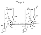
- two buried metal structures 101, 102 such as pipes that can be used for example to transport water, gas or hydrocarbons, or protective conduits for the electric cables.
- the two structures 101, 102 are spaced from each other by a distance l and are each provided with a potential tap 103, 104, that is to say an electrical connection perfectly isolated from on the ground, which connects the buried structure 101 resp. 102 and a potential measurement point located above the ground.
- two calibrated control samples 105, 106 are used, made of the same metal or metal alloy as the buried structures 101, 102 whose interactions are to be determined (for example steel, cast iron, copper, lead).
- the control samples 105, 106 are in the form of calibrated stakes placed in line with the pipes 101, 102 with a spacing l ′ which corresponds to the distance l between the pipes 101, 102 at the location of the measurements.
- the calibrated control samples 105, 106 have a contact surface with the ground which may advantageously be of the order of 100 cm2.
- the control specimens 105, 106 are thus placed in the vicinity of the ground surface, and can be very easily temporarily put in place when measurements are made nearby.
- potential sockets 103, 104 which are generally installed during the installation of the pipes 101, 102.
- the test specimens 105, 106 may not be strictly superimposed on the buried structures 101, 102 and may be slightly offset with respect to these, if the nature of the subsoil is relatively homogeneous. However, the distance d between each of the buried structures 101, 102 and the corresponding control specimen 105, 106 should remain much less than the distances between the DC sources, such as cathodic protection devices not shown, and the structures. buried 101, 102.
- Reference electrodes 107, 108 are installed in the vicinity of the ground surface as close as possible to the test specimens 105, 106, in order to limit as much as possible the voltage drop in the ground during the voltage measurements carried out between the test specimens 105, 106 and the reference electrodes 107, 108.
- the reference electrodes 107, 108 are removable like the control samples and can be put in place during the measurements. Each reference electrode constitutes an impolarizable half-cell.
- the reference electrodes may for example be constituted by copper-copper sulphate electrodes (Cu / CuSO4 electrodes).
- the reference electrodes 107, 108 have a small diameter, preferably less than or equal to about 20 mm.
- each sensor 117, 118 may comprise a control test piece 105, 106 comprising a rod anchored substantially vertically in the ground from from the surface of the ground, and a reference electrode 107, 108 inclined at an angle of between approximately 20 ° and 50 ° relative to the vertical by presenting a lower end situated in the vicinity of the ground surface in the immediate vicinity of the rod anchored in the ground, the test specimen and the reference electrode being secured by a common support 2.
- the measuring device associated with the pipes 101, 102, the test specimens 105, 106 and the reference electrodes 107, 108 comprises two simple switches 111, 112, two simple inverters 109, 110, two voltage measuring devices 113, 114 such as millivoltmeters with high internal resistance greater than about one megohm per volt, and two devices for measuring current intensity 115, 116 such as milliammeters with voltage drop less than about 30 mV for ranges of measurement between for example 50 micro-amps and 100 milli-amps.
- the first simple switch 111 allows a selective connection between the potential test 103 of the first pipe 101 and a first terminal of the milliammeter 115 whose other terminal is connected to the first test specimen 105
- the second switch 112 ensures a selective connection between the potential test 104 of the second pipe 102 and a first terminal of the milliammeter 116, the other terminal of which is connected to the second test specimen 106.
- the first inverter 109 makes it possible to connect a terminal of the millivoltmeter 113, the other terminal of which is connected to the reference electrode 107, selectively either to the potential test 103 (movable switch in position Ec) or to the test specimen 105 (movable switch in position And).
- the second inverter 110 makes it possible to connect a terminal of the millivoltmeter 114, the other terminal of which is connected to the reference electrode 108, selectively either to the potential tap 104 (movable switch in position Ec) or to the witness specimen 106 (movable switch in position Et).
- the device shown diagrammatically in FIG. 1 makes it possible to carry out a whole series of various measurements as a function of the position of the inverters 109, 110 and of the switches 111, 112.
- a first step it is possible to carry out measurements of the potentials of the pipes 101 and 102 which can be assimilated to traditional measurements, the cathodic protections or other sources of direct current associated with the pipes 101, 102 being in service. For this, it is sufficient that the reversers 109 and 110 are in the position Ec and that the switches 111 and 112 are open.
- a second step it is possible to carry out measurements of the potentials of the control samples 105 and 106. These measurements must be carried out after a stabilization time, which can be of the order of fifteen minutes, after the positioning of the witnesses. To carry out these measurements, it is sufficient that the inverters 109 and 110 are in position E and that the switches 111 and 112 are open.
- the measurements carried out during the first two preceding stages give the initial state of the structures 101, 102, before any search for influence.
- Complementary measurements make it possible to simulate coating defects on the structures 101, 102, these defects being calibrated according to a size (for example 100 cm 2) which corresponds to the surface of the control specimens 105, 106 which are in contact with the ground.
- the additional coating defect simulation measurements which use the control samples 105, 106, can be carried out in two different ways.
- Dc generators such as cathodic protection devices
- Dc generators are taken out of service successively on structures 101 and 102 using cyclic switches, and for durations of less than about three seconds.
- the cut-off times are never greater than a value of the order of one twentieth of the time for commissioning the DC generator.
- Tables I and II summarize the measurements of the initial state of the structures 101, 102, the cathodic protections or other sources of direct current associated with these structures being in service while the table II summarizes the measures of interaction proper which imply putting in protective selections cathodic or other direct current sources associated with the works.
- the graphs in FIGS. 6 to 9 represent different possible cases of interactions between a structure 50 which constitutes an "influencing" structure, that is to say from which an influence is exerted, and a structure 60 which constitutes a structure "influenced”, that is to say a work which is influenced.
- Each of the structures 50, 60 is represented by a vertical line and vectors 51 to 53, 61 to 63 illustrate, depending on whether their arrow is oriented towards the vertical line or distant from the vertical line, currents which enter the structure or currents which leave it, the intensity of the currents being itself symbolized by the length of the vectors.
- the vectors 51 to 53 and 61 to 63 are determined by implementing the method according to the invention, that is to say by simultaneously measuring the potentials and the intensities of the bias current in the control test pieces 105, 106 associated with the structures 101, 102 symbolized by lines 50 and 60.
- the vectors 51 and 61 represent the current inputs or outputs respectively on the structures 101, 102 while all the DC generators associated with the structures 101, 102 are in service.
- the vectors 52 and 62 represent the current inputs or outputs respectively on the structures 101, 102 while only the direct current generator (s) associated with the first structure 101 are in service.
- the vectors 53 and 63 represent the current inputs or outputs respectively on the structures 101, 102 while only the direct current generator (s) associated with the second structure 102 are in service.
- FIG. 6 corresponds to the case of a dangerous unfavorable influence exerted by the structure symbolized by the line 50 on the structure symbolized by the line 60.
- vectors 61 and 62 indicate current outputs.
- the vector 63 indicates current inputs when the direct current source associated with the structure 50 is out of service.
- FIG. 7 corresponds to the case of a damaging unfavorable influence exerted by the structure 50 on the structure 60.
- the vector 62 of the currents flowing in the structure 60 is oriented in a way that represents a current output.
- the vector 63 indicates current inputs when the direct current source associated with the structure 50 is out of service.
- the vector 61 indicates current inputs which correspond to the algebraic sum of the vectors 62 and 63 when the direct current sources of the structures 50 and 60 are in service.
- FIG. 8 corresponds to the case of a non-harmful unfavorable influence exerted by the structure 50 on the structure 60.
- the currents 61, 62, 63 are in the form of incoming currents for the structure 60, even if the intensity of these currents is minimal in the case where the direct current source associated with the structure 60 is out of service (vector 62) and if the intensity of the incoming currents is maximum in the case where the direct current source associated with the structure 50 is out of service (vector 63).
- FIG. 9 corresponds to the case of a favorable influence exerted by the structure 50 on the structure 60.
- all the currents 61, 62, 63 are in the form of incoming currents for the structure 60, but in FIG. 9, it is the vector 61, corresponding to the case where all the direct current sources associated with the structures 50, 60 are in service, which represents the maximum intensity.
- the vector 62, corresponding to the case where the current source associated with the structure 60 is out of service represents the minimum intensity.
- the metal structures 101, 102, the test specimens 105, 106 and the reference electrodes 107, 108 are represented symbolically to show their different electrical connections with the circuits of the measuring device via the relays 119, 120 which constitute the inverters 109, 110 and the switches 111, 112.
- Resistors 121, 122 are connected in series with the contacts of the switches 111, 112 respectively and constitute shunts to serve for measuring the intensity of the currents of polarization flowing between the witness 105 and the structure 101, respectively between the witness 106 and the structure 102.
- a sample and hold device 123 comprising four isolated differential channels 124 to 127 makes it possible to make a measurement simultaneously on the four measurement channels constituted by the current measurement channels 126, 127 (signal sockets at the terminals of the shunts 121, 122) and the voltage measurement channels 124, 125 (differential voltage signal sockets between the contacts movable reversers 109 or 110 which can be selectively connected to structures 101 or 102 or to test specimens 105 or 106, and reference electrodes 107 and 108).
- the sampler-blocker 123 is constituted by a relay having eight working contacts and which is provided in each channel 124 to 127 with output capacitors 128 to 131 to store the measured values.
- the signals from the sampler-blocker 123 are directed to a multiplexer 132 which includes four pairs of electronic switches 133 to 136 corresponding to the four measurement channels and selectively controlled from a control circuit 146 so as not to leave pass only one differential signal at a time, completely isolating the other signals.
- the signals are directed either to a voltage amplifier 137, i.e. to a current amplifier 140.
- a second multiplexer 141 selects a voltage channel or a current channel and directs the signal to a low-pass filter 142 intended to suppress noise.
- the output of the filter 142 is connected to an analog-digital converter 143 which transmits the measured value to a microprocessor 144.
- the microprocessor 144 is connected by an address and data bus to memories 145 comprising a program memory 145a and a memory working 145b to store data.
- the microprocessor 144 controls the progress of the measurements in connection with a real-time clock 147 for the timing of the various operations, and the circuit 146 for monitoring and sequencing of the measurements which comprises inter alia an input-output decoder and a user interface connected to a control keyboard 148 for entering the parameters and indicating by the operator the measurement phases to be carried out.
- a display 149 which may for example be a four-line, twenty-four character liquid crystal display, is connected to circuit 146 to display the results of the measurements and indicate the operation in progress.
- An interface 150 can also be connected to the control circuit 146 to allow all the results to be restored on a printer.
- the automatic device of FIG. 2 sends pulses via the control circuit 146 control relay 119, 120 and a control pulse on the ACQ input of the sampler-blocker 123 in order to simultaneously carry out measurements on all channels.
- the measurement values are temporarily stored by the charge of the capacitors 128 to 131.
- the control circuit 146 can then, via the SEL inputs of the multiplexer 132, select the channels 133 to 136 one after the other to provide, after amplification, analog-digital filtering and conversion, digital values representing first and second voltages and first and second current intensities. It will be noted that with the device in FIG. 2, although only one analog-digital converter 143 is used, the measurements may well be really simultaneous.
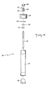
- FIGS. 3 to 5 an example of a sensor which is particularly well suited to implementing the method according to the invention and which performs the functions of the sensors referenced 117, 118 in FIG. 1.
- the sensor of FIGS. 3 to 5 groups together on a common insulating support 2 on the one hand a control specimen 1 and on the other hand a reference electrode 8 intended to be placed from the surface of the ground approximately at right of a buried metallic structure capable of giving rise to interactions with a neighboring buried metallic structure.
- the support 2 is in the form of a plate (fig 5) and can be made of a plastic material such as PVC.
- the support plate 2 is intended to come to rest on the ground by its underside.
- the plate 2 has a first through hole 29 in which is engaged the insulating body 3 forming a handle of the test specimen 1.
- Two other holes 31, 32 are made in the plate 2 to receive female plugs 6, 7 for connection connected by connecting wires 12, 13 respectively to a male plug 6a for connection with the head 5 of the control specimen 1 and to a lug 27 for connection to the reference electrode 8 (fig 3).
- a connector 4 of plastic material such as PVC, provided with two male pins of different sections intended to fit in the female pins 6, 7 provides by the wires 14 and 15 the electrical connections between the test specimen 1 and the reference electrode 8 on the one hand, and the measurement circuits such as elements 109, 111, 113, 115 or 110, 112, 114, 116 in FIG. 1 or elements 119 to 150 in FIG. 2.
- the test specimen 1 in FIG. 3 has the shape of a stake with a metal head 5 engaged on a central metal rod 35 terminated by a point 16 at its lower part.
- the part of the central rod 35 which emerges from the body 3 for holding in the support 2 is polished and has a calibrated surface, which may for example be of the order of 100 cm 2.
- the body 3 and the rod 35 are made integral with one another by pins 10, 11.
- the lower part 17 of the body 3 which protrudes under the plate 2 for a short distance has a frustoconical shape for s' engage in the surface part of the ground and allow the reference electrode 8 to come through its lower end 19, which forms a plug which may be made of wood, place itself in the immediate vicinity of the rod buried 35 in the surface part of the sub- ground.
- the electrode 8 comprises a body 18, for example made of PVC, held by a screw 9 in the support 2, and a central metal bar 20, which is copper in the case of an electrode of the Cu / CuSO4 type.
- FIG. 4 shows the upper plug 24 of the electrode 8, which is provided with a knurling on its external face and a thread on its internal face.
- the reference 21 designates an internal nut for holding the central bar 20 of the electrode, the reference 22 a washer and the reference 23 a sealing washer.
- the upper end of the bar 20 which emerges from the upper plug 24 cooperates itself with a washer 25, a first nut 26, an electrical connection terminal 27 and a second upper nut 28 provided with a knurling.
Landscapes
- Chemical & Material Sciences (AREA)
- Life Sciences & Earth Sciences (AREA)
- Immunology (AREA)
- Pathology (AREA)
- Environmental Sciences (AREA)
- Physics & Mathematics (AREA)
- Health & Medical Sciences (AREA)
- Ecology (AREA)
- Analytical Chemistry (AREA)
- Biochemistry (AREA)
- General Health & Medical Sciences (AREA)
- Engineering & Computer Science (AREA)
- Environmental & Geological Engineering (AREA)
- Biodiversity & Conservation Biology (AREA)
- General Physics & Mathematics (AREA)
- Materials Engineering (AREA)
- Mechanical Engineering (AREA)
- Metallurgy (AREA)
- Organic Chemistry (AREA)
- Investigating Or Analyzing Materials By The Use Of Electric Means (AREA)
- Prevention Of Electric Corrosion (AREA)
- Geophysics And Detection Of Objects (AREA)
- Testing Resistance To Weather, Investigating Materials By Mechanical Methods (AREA)
- Analysing Materials By The Use Of Radiation (AREA)
Priority Applications (1)
| Application Number | Priority Date | Filing Date | Title |
|---|---|---|---|
| AT90403730T ATE103643T1 (de) | 1989-12-27 | 1990-12-21 | Verfahren und vorrichtung zur bestimmung der von in unterirdischen, benachbarten, metallischen strukturen fliessenden kontinuierlichen stroemen verursachten wechselwirkungen. |
Applications Claiming Priority (2)
| Application Number | Priority Date | Filing Date | Title |
|---|---|---|---|
| FR8917281 | 1989-12-27 | ||
| FR8917281A FR2656426B1 (fr) | 1989-12-27 | 1989-12-27 | Procede et dispositif de determination des interactions dues a des courants continus sur des structures metalliques enterrees voisines. |
Publications (2)
| Publication Number | Publication Date |
|---|---|
| EP0435761A1 true EP0435761A1 (de) | 1991-07-03 |
| EP0435761B1 EP0435761B1 (de) | 1994-03-30 |
Family
ID=9389033
Family Applications (1)
| Application Number | Title | Priority Date | Filing Date |
|---|---|---|---|
| EP90403730A Expired - Lifetime EP0435761B1 (de) | 1989-12-27 | 1990-12-21 | Verfahren und Vorrichtung zur Bestimmung der von in unterirdischen, benachbarten, metallischen Strukturen fliessenden kontinuierlichen Strömen verursachten Wechselwirkungen |
Country Status (6)
| Country | Link |
|---|---|
| US (1) | US5144253A (de) |
| EP (1) | EP0435761B1 (de) |
| AT (1) | ATE103643T1 (de) |
| CA (1) | CA2033218A1 (de) |
| DE (1) | DE69007763T2 (de) |
| FR (1) | FR2656426B1 (de) |
Cited By (2)
| Publication number | Priority date | Publication date | Assignee | Title |
|---|---|---|---|---|
| FR2983303A1 (fr) * | 2011-11-30 | 2013-05-31 | Sylvain Batard | Mesure de la resistance au sol d'une structure metallique ou de la resistivite du sol, en utilisant une structure metallique enterree de grande taille, eventuellement sous protection cathodique |
| EP2738548A1 (de) * | 2012-11-30 | 2014-06-04 | Grdf | Verfahren und Vorrichtung zum Messen eines Erdungswiderstands und des Bodenwiderstands |
Families Citing this family (13)
| Publication number | Priority date | Publication date | Assignee | Title |
|---|---|---|---|---|
| US5691648A (en) * | 1992-11-10 | 1997-11-25 | Cheng; David | Method and apparatus for measuring sheet resistance and thickness of thin films and substrates |
| US5495178A (en) * | 1992-11-10 | 1996-02-27 | Cheng; David | Method and apparatus for measuring film thickness |
| JP3058844B2 (ja) * | 1997-06-03 | 2000-07-04 | 東京瓦斯株式会社 | 鋼製プローブを用いたカソード防食状況の判定方法及びその装置 |
| US6404203B1 (en) * | 1999-10-22 | 2002-06-11 | Advanced Geosciences, Inc. | Methods and apparatus for measuring electrical properties of a ground using an electrode configurable as a transmitter or receiver |
| US7317321B2 (en) * | 2001-06-22 | 2008-01-08 | Ntg, Inc. | Methods and systems for automated pipeline testing |
| EP1623250B1 (de) * | 2003-04-18 | 2016-08-03 | Advanced Geosciences, Inc. | Techniken zur oberflächenuntersuchung und überwachung |
| US20110238347A1 (en) * | 2010-03-24 | 2011-09-29 | Elecsys Corporation | Apparatus and system for automated pipeline testing |
| CN102338735B (zh) * | 2010-07-14 | 2014-04-02 | 中国石油天然气股份有限公司 | 多干扰源杂散电流干扰室内模拟装置 |
| US20140062490A1 (en) * | 2012-04-06 | 2014-03-06 | Michael Alexander St Leger NEUMAN | Cathodic protection monitoring method, system and components |
| IT201700098015A1 (it) * | 2017-08-31 | 2019-03-03 | Claudio Borsello | Apparato per generare energia elettrica a partire da un potenziale elettrico sulla superficie del globo terracqueo |
| US10705984B1 (en) * | 2018-09-26 | 2020-07-07 | Cadence Design Systems, Inc. | High-speed low VT drift receiver |
| CN110656335A (zh) * | 2019-11-01 | 2020-01-07 | 贵州电网有限责任公司 | 一种变电站接地装置阴极保护电位探测系统及其探测方法 |
| CN118653154B (zh) * | 2024-06-27 | 2024-11-19 | 浙江钰烯腐蚀控制股份有限公司 | 控制参比电极失效下阴极保护电源设备正常运行的方法 |
Citations (2)
| Publication number | Priority date | Publication date | Assignee | Title |
|---|---|---|---|---|
| FR2356741A1 (fr) * | 1976-07-01 | 1978-01-27 | Chemoprojekt Projektova Inzeny | Procede pour l'affaiblissement de l'interference de structures metalliques ainsi que montage et capteurs pour la mise en oeuvre de ce procede |
| US4591792A (en) * | 1984-02-08 | 1986-05-27 | Gas Research Institute | Method and apparatus for measuring the polarized potential of a buried or submerged structure protected by impressed current |
Family Cites Families (6)
| Publication number | Priority date | Publication date | Assignee | Title |
|---|---|---|---|---|
| US1978440A (en) * | 1931-08-31 | 1934-10-30 | Edgar R Shepard | Electric measuring device |
| US3649492A (en) * | 1966-06-14 | 1972-03-14 | Union Oil Co | Method for determining the completeness of cathodic protection of corrodible metal structure |
| US3355665A (en) * | 1967-01-03 | 1967-11-28 | Bethlehem Steel Corp | Moisture measuring probe having an insulating material covering less than one-half of the perimeter of the probe |
| NL8103088A (nl) * | 1981-06-26 | 1983-01-17 | Nederlandse Gasunie Nv | Inrichting voor het meten van de potentiaal ten opzichte van de bodem van een kathodisch beschermde metalen constructie. |
| US4659492A (en) | 1984-06-11 | 1987-04-21 | The Lubrizol Corporation | Alkenyl-substituted carboxylic acylating agent/hydroxy terminated polyoxyalkylene reaction products and aqueous systems containing same |
| FR2592484B1 (fr) * | 1985-12-31 | 1988-04-01 | Total France | Procede et dispositif d'analyse de l'effet corrosif du sol et de son environnement sur une structure metallique enterree et application a la localisation de cet effet. |
-
1989
- 1989-12-27 FR FR8917281A patent/FR2656426B1/fr not_active Expired - Lifetime
-
1990
- 1990-12-21 AT AT90403730T patent/ATE103643T1/de not_active IP Right Cessation
- 1990-12-21 US US07/631,319 patent/US5144253A/en not_active Expired - Lifetime
- 1990-12-21 DE DE69007763T patent/DE69007763T2/de not_active Expired - Fee Related
- 1990-12-21 EP EP90403730A patent/EP0435761B1/de not_active Expired - Lifetime
- 1990-12-27 CA CA002033218A patent/CA2033218A1/en not_active Abandoned
Patent Citations (2)
| Publication number | Priority date | Publication date | Assignee | Title |
|---|---|---|---|---|
| FR2356741A1 (fr) * | 1976-07-01 | 1978-01-27 | Chemoprojekt Projektova Inzeny | Procede pour l'affaiblissement de l'interference de structures metalliques ainsi que montage et capteurs pour la mise en oeuvre de ce procede |
| US4591792A (en) * | 1984-02-08 | 1986-05-27 | Gas Research Institute | Method and apparatus for measuring the polarized potential of a buried or submerged structure protected by impressed current |
Non-Patent Citations (2)
| Title |
|---|
| MATERIALS PERFORMANCE. vol. 20, no. 2, février 1981, HOUSTON US pages 19 - 24; R.L. SEIFERT: "The calculation of true cathodic protection interference drain current from easily measured field data" * |
| MATERIALS PERFORMANCE. vol. 22, no. 8, août 1983, HOUSTON US pages 12 - 20; J. POLAK: "The use of multipurpose measuring probes to assess the adequacy of cathodic protection of buried pipelines" * |
Cited By (2)
| Publication number | Priority date | Publication date | Assignee | Title |
|---|---|---|---|---|
| FR2983303A1 (fr) * | 2011-11-30 | 2013-05-31 | Sylvain Batard | Mesure de la resistance au sol d'une structure metallique ou de la resistivite du sol, en utilisant une structure metallique enterree de grande taille, eventuellement sous protection cathodique |
| EP2738548A1 (de) * | 2012-11-30 | 2014-06-04 | Grdf | Verfahren und Vorrichtung zum Messen eines Erdungswiderstands und des Bodenwiderstands |
Also Published As
| Publication number | Publication date |
|---|---|
| EP0435761B1 (de) | 1994-03-30 |
| FR2656426A1 (fr) | 1991-06-28 |
| FR2656426B1 (fr) | 1992-04-30 |
| CA2033218A1 (en) | 1991-06-28 |
| DE69007763D1 (de) | 1994-05-05 |
| DE69007763T2 (de) | 1994-08-04 |
| ATE103643T1 (de) | 1994-04-15 |
| US5144253A (en) | 1992-09-01 |
Similar Documents
| Publication | Publication Date | Title |
|---|---|---|
| EP0435761B1 (de) | Verfahren und Vorrichtung zur Bestimmung der von in unterirdischen, benachbarten, metallischen Strukturen fliessenden kontinuierlichen Strömen verursachten Wechselwirkungen | |
| EP2602609A1 (de) | Überwachung einer Rohrleitung unter kathodischem Korrosionsschutz | |
| CA2344241C (fr) | Procede et dispositif pour la localisation d'un defaut d'isolement d'un cable electrique | |
| FR2689241A1 (fr) | Sonde de mesure de l'état électrique d'une structure enterrée, circuit comportant une telle sonde et procédé de prise de mesures. | |
| FR2508648A1 (fr) | Dispositif pour mesurer le potentiel par rapport au sol d'une structure protegee cathodiquement | |
| WO2007107652A2 (fr) | Cellule de mesure de potentiel pour la surveillance des installations a protection cathodique par soutirage | |
| FR2569847A1 (fr) | Dispositif de detection et de localisation d'entree d'eau pour flute marine | |
| EP1160932A1 (de) | Wasserdichte elektrische Verbindungsvorrichtung für Elektroden mit geschirmten Kable und System für Petrophysicalische Messungen | |
| FR2772923A1 (fr) | Circuit electronique de surveillance de tension electrique | |
| FR2703458A1 (fr) | Procédé et dispositif de mesure du potentiel électrochimique réel d'un élément de construction dans un électrolyte tel une conduite enfouie dans le sol, protégée cathodiquement contre la corrosion. | |
| FR2490346A1 (de) | ||
| FR3044487A1 (fr) | Procede et dispositif de detection d'un arc electrique dans une installation photovoltaique | |
| EP3692352B1 (de) | Vorrichtung zur kontinuierlichen überwachung von defekten in einem rohrleitungsabschnitt sowie ein überwachungssystem mit mindestens zwei überwachungsvorrichtungen | |
| EP0077757A1 (de) | Verfahren zur Fehlererkennung einer dielektrischen Schicht an der Oberfläche eines elektrisch leitenden Substrats | |
| FR2850463A1 (fr) | Procede et dispositif pour determiner la tension d'arc en soudage a l'arc | |
| EP1250607B1 (de) | Verfahren und vorrichtung zur überwachung eines telekommunikationskabels | |
| EP0330549B1 (de) | Gerät zur kontinuierlichen Messung der Korrosionsschnelligkeit in einer Flüssigkeit, durch ein elektrochemisches Verfahren | |
| FR2489197A1 (fr) | Circuit de surveillance pour appareil de soudage electrique | |
| EP0454578A1 (de) | Verfahren zum Testen der Zweckmässigkeit der elektromagnetischen Abschirmung eines Leiters und Anordnung dafür | |
| FR3042865A1 (fr) | Dispositif pour la mesure du potentiel electrochimique a courant coupe d'une structure contenant du metal soumise a une protection cathodique par anodes sacrificielles | |
| EP0494012B1 (de) | Verfahren und Vorrichtung für die Überprüfung des elektrischen Isolierungszustands einer elektrisch leitenden Konstruktion | |
| FR2983303A1 (fr) | Mesure de la resistance au sol d'une structure metallique ou de la resistivite du sol, en utilisant une structure metallique enterree de grande taille, eventuellement sous protection cathodique | |
| EP0852714A1 (de) | Verfahren und vorrichtung zur kontrolle der eigenschaften einer oberfläche eines elementes einer zirkoniumlegierung,sowie anwendung für die kontrolle der brennelemente von kernkraftwerken | |
| CA1177536A (fr) | Detection et localisation de defauts electriques et decharges partielles | |
| EP0353147A1 (de) | Verfahren und Vorrichtung zur Bestimmung der Korrosionsgeschwindigkeit von einer vergrabenen oder versenkten ununterbrochenen metallischen Struktur |
Legal Events
| Date | Code | Title | Description |
|---|---|---|---|
| PUAI | Public reference made under article 153(3) epc to a published international application that has entered the european phase |
Free format text: ORIGINAL CODE: 0009012 |
|
| 17P | Request for examination filed |
Effective date: 19901228 |
|
| AK | Designated contracting states |
Kind code of ref document: A1 Designated state(s): AT BE CH DE DK ES FR GB GR IT LI LU NL SE |
|
| 17Q | First examination report despatched |
Effective date: 19930507 |
|
| GRAA | (expected) grant |
Free format text: ORIGINAL CODE: 0009210 |
|
| AK | Designated contracting states |
Kind code of ref document: B1 Designated state(s): AT BE CH DE DK ES FR GB GR IT LI LU NL SE |
|
| PG25 | Lapsed in a contracting state [announced via postgrant information from national office to epo] |
Ref country code: ES Free format text: THE PATENT HAS BEEN ANNULLED BY A DECISION OF A NATIONAL AUTHORITY Effective date: 19940330 Ref country code: GR Free format text: LAPSE BECAUSE OF FAILURE TO SUBMIT A TRANSLATION OF THE DESCRIPTION OR TO PAY THE FEE WITHIN THE PRESCRIBED TIME-LIMIT Effective date: 19940330 Ref country code: DK Effective date: 19940330 Ref country code: AT Effective date: 19940330 Ref country code: NL Effective date: 19940330 Ref country code: SE Free format text: THE PATENT HAS BEEN ANNULLED BY A DECISION OF A NATIONAL AUTHORITY Effective date: 19940330 |
|
| REF | Corresponds to: |
Ref document number: 103643 Country of ref document: AT Date of ref document: 19940415 Kind code of ref document: T |
|
| REF | Corresponds to: |
Ref document number: 69007763 Country of ref document: DE Date of ref document: 19940505 |
|
| GBT | Gb: translation of ep patent filed (gb section 77(6)(a)/1977) |
Effective date: 19940415 |
|
| ITF | It: translation for a ep patent filed | ||
| NLV1 | Nl: lapsed or annulled due to failure to fulfill the requirements of art. 29p and 29m of the patents act | ||
| PG25 | Lapsed in a contracting state [announced via postgrant information from national office to epo] |
Ref country code: LI Effective date: 19941231 Ref country code: CH Effective date: 19941231 Ref country code: LU Free format text: LAPSE BECAUSE OF NON-PAYMENT OF DUE FEES Effective date: 19941231 |
|
| PLBE | No opposition filed within time limit |
Free format text: ORIGINAL CODE: 0009261 |
|
| STAA | Information on the status of an ep patent application or granted ep patent |
Free format text: STATUS: NO OPPOSITION FILED WITHIN TIME LIMIT |
|
| 26N | No opposition filed | ||
| REG | Reference to a national code |
Ref country code: CH Ref legal event code: PL |
|
| PGFP | Annual fee paid to national office [announced via postgrant information from national office to epo] |
Ref country code: FR Payment date: 19981231 Year of fee payment: 9 |
|
| PG25 | Lapsed in a contracting state [announced via postgrant information from national office to epo] |
Ref country code: FR Free format text: LAPSE BECAUSE OF NON-PAYMENT OF DUE FEES Effective date: 20000831 |
|
| REG | Reference to a national code |
Ref country code: FR Ref legal event code: ST |
|
| REG | Reference to a national code |
Ref country code: GB Ref legal event code: IF02 |
|
| PGFP | Annual fee paid to national office [announced via postgrant information from national office to epo] |
Ref country code: BE Payment date: 20081125 Year of fee payment: 19 Ref country code: IT Payment date: 20081218 Year of fee payment: 19 |
|
| PGFP | Annual fee paid to national office [announced via postgrant information from national office to epo] |
Ref country code: DE Payment date: 20090102 Year of fee payment: 19 |
|
| PGFP | Annual fee paid to national office [announced via postgrant information from national office to epo] |
Ref country code: GB Payment date: 20081125 Year of fee payment: 19 |
|
| BERE | Be: lapsed |
Owner name: *GAZ DE FRANCE (SERVICE NATIONAL) Effective date: 20091231 |
|
| GBPC | Gb: european patent ceased through non-payment of renewal fee |
Effective date: 20091221 |
|
| PG25 | Lapsed in a contracting state [announced via postgrant information from national office to epo] |
Ref country code: BE Free format text: LAPSE BECAUSE OF NON-PAYMENT OF DUE FEES Effective date: 20091231 |
|
| PG25 | Lapsed in a contracting state [announced via postgrant information from national office to epo] |
Ref country code: DE Free format text: LAPSE BECAUSE OF NON-PAYMENT OF DUE FEES Effective date: 20100701 |
|
| PG25 | Lapsed in a contracting state [announced via postgrant information from national office to epo] |
Ref country code: GB Free format text: LAPSE BECAUSE OF NON-PAYMENT OF DUE FEES Effective date: 20091221 |
|
| PG25 | Lapsed in a contracting state [announced via postgrant information from national office to epo] |
Ref country code: IT Free format text: LAPSE BECAUSE OF NON-PAYMENT OF DUE FEES Effective date: 20091221 |