EP2738548A1 - Verfahren und Vorrichtung zum Messen eines Erdungswiderstands und des Bodenwiderstands - Google Patents
Verfahren und Vorrichtung zum Messen eines Erdungswiderstands und des Bodenwiderstands Download PDFInfo
- Publication number
- EP2738548A1 EP2738548A1 EP12306502.1A EP12306502A EP2738548A1 EP 2738548 A1 EP2738548 A1 EP 2738548A1 EP 12306502 A EP12306502 A EP 12306502A EP 2738548 A1 EP2738548 A1 EP 2738548A1
- Authority
- EP
- European Patent Office
- Prior art keywords
- circuit
- electrical connection
- electrode
- ground
- acquisition
- Prior art date
- Legal status (The legal status is an assumption and is not a legal conclusion. Google has not performed a legal analysis and makes no representation as to the accuracy of the status listed.)
- Ceased
Links
- 238000000034 method Methods 0.000 title claims abstract description 32
- 239000002689 soil Substances 0.000 title claims abstract description 14
- 238000012545 processing Methods 0.000 claims abstract description 20
- 238000005259 measurement Methods 0.000 claims description 46
- 238000004364 calculation method Methods 0.000 claims description 4
- 230000003595 spectral effect Effects 0.000 claims description 4
- 238000001914 filtration Methods 0.000 claims description 3
- 238000002347 injection Methods 0.000 description 6
- 239000007924 injection Substances 0.000 description 6
- 238000004210 cathodic protection Methods 0.000 description 5
- RLLPVAHGXHCWKJ-IEBWSBKVSA-N (3-phenoxyphenyl)methyl (1s,3s)-3-(2,2-dichloroethenyl)-2,2-dimethylcyclopropane-1-carboxylate Chemical compound CC1(C)[C@H](C=C(Cl)Cl)[C@@H]1C(=O)OCC1=CC=CC(OC=2C=CC=CC=2)=C1 RLLPVAHGXHCWKJ-IEBWSBKVSA-N 0.000 description 4
- 238000010616 electrical installation Methods 0.000 description 3
- 238000012935 Averaging Methods 0.000 description 2
- 238000003780 insertion Methods 0.000 description 2
- 230000037431 insertion Effects 0.000 description 2
- 238000009434 installation Methods 0.000 description 2
- 239000002184 metal Substances 0.000 description 2
- 229910052751 metal Inorganic materials 0.000 description 2
- 239000000243 solution Substances 0.000 description 2
- 238000011282 treatment Methods 0.000 description 2
- 230000001960 triggered effect Effects 0.000 description 2
- RYGMFSIKBFXOCR-UHFFFAOYSA-N Copper Chemical compound [Cu] RYGMFSIKBFXOCR-UHFFFAOYSA-N 0.000 description 1
- 230000001427 coherent effect Effects 0.000 description 1
- 230000000295 complement effect Effects 0.000 description 1
- 229910052802 copper Inorganic materials 0.000 description 1
- 239000010949 copper Substances 0.000 description 1
- ARUVKPQLZAKDPS-UHFFFAOYSA-L copper(II) sulfate Chemical compound [Cu+2].[O-][S+2]([O-])([O-])[O-] ARUVKPQLZAKDPS-UHFFFAOYSA-L 0.000 description 1
- 238000010586 diagram Methods 0.000 description 1
- 239000012153 distilled water Substances 0.000 description 1
- 230000000694 effects Effects 0.000 description 1
- 238000002848 electrochemical method Methods 0.000 description 1
- 230000008030 elimination Effects 0.000 description 1
- 238000003379 elimination reaction Methods 0.000 description 1
- 238000011156 evaluation Methods 0.000 description 1
- 230000010287 polarization Effects 0.000 description 1
- 229920006395 saturated elastomer Polymers 0.000 description 1
- XLYOFNOQVPJJNP-UHFFFAOYSA-N water Chemical compound O XLYOFNOQVPJJNP-UHFFFAOYSA-N 0.000 description 1
Images

Classifications
-
- G—PHYSICS
- G01—MEASURING; TESTING
- G01N—INVESTIGATING OR ANALYSING MATERIALS BY DETERMINING THEIR CHEMICAL OR PHYSICAL PROPERTIES
- G01N17/00—Investigating resistance of materials to the weather, to corrosion, or to light
- G01N17/02—Electrochemical measuring systems for weathering, corrosion or corrosion-protection measurement
-
- G—PHYSICS
- G01—MEASURING; TESTING
- G01R—MEASURING ELECTRIC VARIABLES; MEASURING MAGNETIC VARIABLES
- G01R27/00—Arrangements for measuring resistance, reactance, impedance, or electric characteristics derived therefrom
- G01R27/02—Measuring real or complex resistance, reactance, impedance, or other two-pole characteristics derived therefrom, e.g. time constant
- G01R27/20—Measuring earth resistance; Measuring contact resistance, e.g. of earth connections, e.g. plates
Definitions
- the invention relates to a method and a device for measuring an earth resistance and the resistivity of a ground.
- the invention is more particularly, but not exclusively, adapted to measures for controlling the efficiency and conformity of an earth electrode of an electrical installation, to the measures prior to the implementation of a cathodic protection of buried means, or to measures to determine the best location for the installation of a ground.
- such measurements use a so-called “earth ohmmeter” or “tellurometer” means, which means allows the injection of a current into the ground, and the measurement of a resistance between two measurement points. traversed by said stream. From a practical point of view, the current injection and the resistance measurement are carried out via conductive elements, such as stakes, buried in the ground.
- the figure 1 relating to the prior art illustrates the principle of a method of measuring the resistance of a grounding, method from which derive the different variant of the method called "62%".
- the method consists in imposing, by means of a generator (131), the circulation of an electric current between the grounding point (110) and a grounding current stake (121), planted in the ground ( 100), the earth electrode (110) being disconnected from the electrical installation for which it provides protection.
- a second stake (122), said potential-taking, is planted in the ground at a teklle distance from the earth electrode (110) and the current injection pin (121), that said potential tap is in outside the areas (101, 102) of influence of said earth (110) and said current injection pin (121).
- a voltmeter (132) measures the voltage U between the potential tap (122), which is at a zero potential, and the ground connection (110) while a current I is injected into the ground via the current injection pin (121).
- the assembly (130) comprising the voltmeter (132) and the current generator (131) constitutes an earth ohmmeter or tellurometer.
- the figure 1 B illustrates the principle of a method of measuring the resistivity of the soil (100) by a 4-point method known as the Wenner method. method also uses an ohmmeter (130) of earth and 4 stakes (141, 142, 151, 152) aligned at precise distances and depths.
- the two outer stakes (141, 142) are connected to the generator (132) and the measurement of the tension between the two measuring stakes (151, 152) placed between the injection stakes (141, 142) makes it possible to determine the resistance of the circuit thus created and consequently the resistivity of the ground (100).
- the document FR 2,726,083 discloses a method of controlling the cathodic protection of a buried pipe, which pipe is subject to cathodic protection by a forced current device or withdrawal.
- Said control method comprises measuring the resistivity of the ground along said pipe by means of a tellurometer.
- the term "ground resistance” designates a measurand for determining the resistivity of the ground or the resistance of an electrical circuit integrating a portion of ground or the ground resistance of a buried structure such as the resistance of a grounding.
- the measurement principles described above are combined and incorporate, according to some embodiments, a reference electrode. In all cases the use of an earth ohmmeter or tellurometer is necessary.
- the device of the invention does not use a current generator and uses only one electrode inserted into the ground. This device is thus faster, simpler and safer to implement and requires a smaller surface area due to the single picket electrode.
- the invention can be implemented according to the advantageous embodiments described below, which can be considered individually or in any technically operative combination.
- the device that is the subject of the invention makes it possible to control so-called "triggered-triggered” measurements of the circuit created between the buried structure and the electrode.
- the acquisition and processing unit comprises timing means capable of timing the control of the switching means.
- the device allows the programming of a series of measurements in order to follow an evolution or to improve the accuracy of said measurements.
- the acquisition and processing unit comprises memory means and calculation means able to store and analyze a series of successive measurements.
- the measurement accuracy is improved by the statistical processing of several successive measurements.
- the acquisition and processing unit comprises filtering means capable of extracting a spectral component from measurements made by the ammeter and the voltmeter.
- filtering means capable of extracting a spectral component from measurements made by the ammeter and the voltmeter.
- the device which is the subject of the invention is particularly suitable for measuring the impedance of an earth electrode.
- the acquisition and processing unit comprises input means capable of acquiring contextual information relating to the measurement.
- the device according to the invention makes it possible, according to this embodiment, to determine the resistivity of the ground from the resistance measurements.
- the picket electrode is a device comprising a reference electrode and a control coupon and so-called tilting means for switching the connection of the electrical connection circuit to the reference electrode or the control coupon.
- the device makes it possible to measure the electrochemical potential of the structure connected to the electrical connection means.
- the acquisition and processing unit comprises means for controlling the tilting means.
- complex measurement protocols are automatically feasible.
- the method of the invention allows, from the insertion of a single stake and a simple measurement sequence to quickly obtain a value of the soil resistance.
- the simplicity of implementation makes it possible to repeat the measurement by varying the conditions, such as the location of the stake, the distance to the buried structure, the climatic conditions, so as to obtain a reliable and detailed image of soil resistance.
- Said statistical processing makes it possible to improve the accuracy and reliability of the measurements by eliminating, in particular by means of averaging techniques, factors of variability of said measurements.
- step vii) is carried out by modifying the time separating steps iii) and iv) with each repetition and step viii) comprises the elimination of the incoherent measurements.
- steps viii) comprises the elimination of the incoherent measurements.
- step ix is carried out by the input means.
- This embodiment is the simplest implementation and requires the least hardware.
- step xi) is carried out by performing steps iii) through vi) the electrical connection circuit being established between the electrical connection means and the electrode. reference.
- This variant embodiment allows a more precise evaluation of the ground resistance of the buried structure.
- said device comprises an electrical circuit (230) connecting an electrode (221) said stake inserted into the ground (100).
- said electrode (221) is in the form of a metal post or in the form of a control coupon commonly used in the field of electrochemical measurement. Such a control coupon has defined geometric characteristics and thus makes it possible to determine the resistivity of the soil.
- the electrode (221) peg is a ground, in the form of a peg, a plate or a metal mesh. In general, the electrode (221) peg is a structure whose knowledge of the ground resistance is sought.
- the other end of said electrical connecting circuit (230) is connected, by means of an electrical connector (222), to a large buried metallic structure (210), for example, a pipe.
- a large buried metallic structure for example, a pipe.
- Said pipe (210) is or is not subject to cathodic protection.
- a potential difference ⁇ V exists between the pipe (210) and the electrode (221) peg. This potential difference is measured by a voltmeter (231) connected in parallel to each end of the electrical connection circuit (230).
- This potential difference is generated by the cathodic protection by withdrawing the pipe, by the polarization of said pipe in the electrolytic medium constituting the soil (100) or by the presence of so-called stray currents in the soil.
- Switching means (240) make it possible to open or close the electrical connection circuit (230).
- Said electrical connection circuit (230) comprises one or more elements (241) of known impedance. For example a resistor (241) or a capacitance (not shown).
- the electrical connecting circuit (230) is closed, the current flowing in said circuit passes through an ammeter (233) which makes it possible to measure the intensity of said current.
- the electrical connection circuit is purely resistive.
- This electric circuit comprises three resistors in series, the resistance (241) of the value connecting circuit R1 , the ground resistance of the electrode (221) peg, of value R , and the ground resistance of the pipe (210). , of value R2.
- the value of R2 is known or at least estimable depending on the nature of the pipe (210), its geometry and the nature of the soil (100).
- the device (200) which is the subject of the invention comprises input means (260) connected to an acquisition and processing unit (250), in the form of a computer comprising memory means.
- the input means thus make it possible to select pre-recorded configurations in the memory means of said calculator in order to evaluate R2.
- said input means (260) comprise a memory card reader, which cards comprise a data record corresponding to a determined measurement situation, data used by the computer (250) to determine R2.
- the picket electrode comprises a reference electrode (225).
- the reference electrode consists of a solution saturated with copper and copper sulphate in distilled water, enclosed in a tube and having a porous tip for bringing said solution into contact with the medium constituting the soil.
- the device according to the invention comprises tilting means (270) for establishing the electrical connection circuit, either with the electrode (221) stake or with the reference electrode (225).
- the tilting means (270) are controlled by the computer.
- the realization of measurement sequences with the reference electrode (225) whose potential is known, makes it possible to determine the resistance R2.
- Advantageously switching means (240) for opening or closing the electrical connection circuit (230) are also controlled by the computer (250).
- the calculator includes a clock and thus offers the possibility of timing several open circuit and closed circuit measurements, as well as controlling the time separating two measurements.
- the voltmeter (232) and the ammeter (233) being connected to the computer (250) which records in its memory means the measurements from these two instruments, a series of measurements with evolutionary times separating the measurement in circuit configuration open and the measurement in closed circuit configuration is performed and the results of these measurements are stored in the memory of the computer (250).
- the computer comprises processing algorithms of the result series corresponding to theoretical or empirically determined cases so as to retain only the coherent measurements and to improve the accuracy of said measurements, in particular by averaging.
- the embodiments described above apply that the voltage source between the electrode (221) peg and the pipe (210) is continuous or alternative.
- the device (200) which is the subject of the invention advantageously comprises filtering means at the computer (250) which means are adapted to measure the spectral impedances of the electrical circuit.
- This embodiment makes it possible to use stray currents, present in the ground, and to exploit said currents as a voltage source in a spectral band around 50 Hz, especially when the electrode (221) post is a ground whose value of resistance is sought.
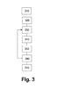
- the method of the invention requires the connection of the electrical connector to the pipe followed by a step of insertion (320) of the stake electrode in the ground.
- a step (330) for closing the link circuit makes it possible to obtain the value of I closed .
- a next step (340) for opening the circuit makes it possible to obtain the value ⁇ V open ⁇ ⁇
- a step (370) of statistical processing makes it possible to compile these results and to improve their accuracy.
- the above description and the exemplary embodiments show that the invention achieves the desired objectives, in particular the combination of the device and the method which are the subject of the invention make it possible to easily carry out measurements of the resistance of the ground, and to dispose of transportable measuring equipment that can be operated by a single person, without danger for the installations and the people circulating in the vicinity of these because of the absence of current generator.
Landscapes
- Life Sciences & Earth Sciences (AREA)
- Biodiversity & Conservation Biology (AREA)
- Ecology (AREA)
- Environmental & Geological Engineering (AREA)
- Environmental Sciences (AREA)
- Physics & Mathematics (AREA)
- Health & Medical Sciences (AREA)
- Chemical & Material Sciences (AREA)
- Analytical Chemistry (AREA)
- Biochemistry (AREA)
- General Health & Medical Sciences (AREA)
- General Physics & Mathematics (AREA)
- Immunology (AREA)
- Pathology (AREA)
- Measurement Of Resistance Or Impedance (AREA)
- Investigating Or Analyzing Materials By The Use Of Electric Means (AREA)
Priority Applications (1)
| Application Number | Priority Date | Filing Date | Title |
|---|---|---|---|
| EP12306502.1A EP2738548A1 (de) | 2012-11-30 | 2012-11-30 | Verfahren und Vorrichtung zum Messen eines Erdungswiderstands und des Bodenwiderstands |
Applications Claiming Priority (1)
| Application Number | Priority Date | Filing Date | Title |
|---|---|---|---|
| EP12306502.1A EP2738548A1 (de) | 2012-11-30 | 2012-11-30 | Verfahren und Vorrichtung zum Messen eines Erdungswiderstands und des Bodenwiderstands |
Publications (1)
| Publication Number | Publication Date |
|---|---|
| EP2738548A1 true EP2738548A1 (de) | 2014-06-04 |
Family
ID=47429694
Family Applications (1)
| Application Number | Title | Priority Date | Filing Date |
|---|---|---|---|
| EP12306502.1A Ceased EP2738548A1 (de) | 2012-11-30 | 2012-11-30 | Verfahren und Vorrichtung zum Messen eines Erdungswiderstands und des Bodenwiderstands |
Country Status (1)
| Country | Link |
|---|---|
| EP (1) | EP2738548A1 (de) |
Cited By (4)
| Publication number | Priority date | Publication date | Assignee | Title |
|---|---|---|---|---|
| CN108804763A (zh) * | 2018-05-07 | 2018-11-13 | 中国南方电网有限责任公司超高压输电公司检修试验中心 | 一种基于分流测试结果的垂直型直流接地极跨步电势计算方法 |
| CN108872709A (zh) * | 2018-08-13 | 2018-11-23 | 西南交通大学 | 一种不同含水量下分层土壤动态电阻特性试验方法 |
| CN109188090A (zh) * | 2018-08-13 | 2019-01-11 | 西南交通大学 | 垂直分层土壤中不同湿度土壤电阻非线性的试验方法 |
| US20230014791A1 (en) * | 2021-07-12 | 2023-01-19 | Titan Hre Llc | Apparatus and system for automated assessment of cathodic protection system for pipelines |
Citations (4)
| Publication number | Priority date | Publication date | Assignee | Title |
|---|---|---|---|---|
| EP0435761A1 (de) * | 1989-12-27 | 1991-07-03 | Gaz De France (Service National) | Verfahren und Vorrichtung zur Bestimmung der von in unterirdischen, benachbarten, metallischen Strukturen fliessenden kontinuierlichen Strömen verursachten Wechselwirkungen |
| US5469048A (en) * | 1994-06-13 | 1995-11-21 | Meridian Oil Inc. | Cathodic protection measurement apparatus |
| FR2726083A1 (fr) | 1994-10-24 | 1996-04-26 | Gaz De France | Procede de controle d'un reseau de conduites metalliques enterrees sous protection cathodique et dispositif pour sa mise en oeuvre |
| US6107811A (en) * | 1998-02-12 | 2000-08-22 | Cc Technologies Laboratories, Inc. | Coupon monitor for cathodic protection system |
-
2012
- 2012-11-30 EP EP12306502.1A patent/EP2738548A1/de not_active Ceased
Patent Citations (4)
| Publication number | Priority date | Publication date | Assignee | Title |
|---|---|---|---|---|
| EP0435761A1 (de) * | 1989-12-27 | 1991-07-03 | Gaz De France (Service National) | Verfahren und Vorrichtung zur Bestimmung der von in unterirdischen, benachbarten, metallischen Strukturen fliessenden kontinuierlichen Strömen verursachten Wechselwirkungen |
| US5469048A (en) * | 1994-06-13 | 1995-11-21 | Meridian Oil Inc. | Cathodic protection measurement apparatus |
| FR2726083A1 (fr) | 1994-10-24 | 1996-04-26 | Gaz De France | Procede de controle d'un reseau de conduites metalliques enterrees sous protection cathodique et dispositif pour sa mise en oeuvre |
| US6107811A (en) * | 1998-02-12 | 2000-08-22 | Cc Technologies Laboratories, Inc. | Coupon monitor for cathodic protection system |
Cited By (6)
| Publication number | Priority date | Publication date | Assignee | Title |
|---|---|---|---|---|
| CN108804763A (zh) * | 2018-05-07 | 2018-11-13 | 中国南方电网有限责任公司超高压输电公司检修试验中心 | 一种基于分流测试结果的垂直型直流接地极跨步电势计算方法 |
| CN108872709A (zh) * | 2018-08-13 | 2018-11-23 | 西南交通大学 | 一种不同含水量下分层土壤动态电阻特性试验方法 |
| CN109188090A (zh) * | 2018-08-13 | 2019-01-11 | 西南交通大学 | 垂直分层土壤中不同湿度土壤电阻非线性的试验方法 |
| CN109188090B (zh) * | 2018-08-13 | 2019-11-05 | 西南交通大学 | 垂直分层土壤中不同湿度土壤电阻非线性的试验方法 |
| US20230014791A1 (en) * | 2021-07-12 | 2023-01-19 | Titan Hre Llc | Apparatus and system for automated assessment of cathodic protection system for pipelines |
| US12105011B2 (en) * | 2021-07-12 | 2024-10-01 | Titan Hre Llc | Apparatus and system for automated assessment of cathodic protection system for pipelines |
Similar Documents
| Publication | Publication Date | Title |
|---|---|---|
| EP2103964B1 (de) | Abschätzverfahren der Dichte der Risse in einem felsigen Milieu | |
| EP2082247B1 (de) | Verfahren und einrichtung zum analysieren eines elektrischen kabelnetzes unter verwendung von pseudozufallssequenzen | |
| EP2737308B1 (de) | Vorrichtung zum messen des freien chloridgehalts von wasser | |
| EP3455452B1 (de) | Verfahren zur bestimmung einer höchstzulässigen wassermenge, die im laufe der zeit aus einer unterirdischen wasserquelle entfernt werden kann | |
| CA2508428A1 (fr) | Detection, localisation et interpretation de decharge partielle | |
| FR2983582A1 (fr) | Surveillance d'une canalisation enterree soumise a protection cathodique | |
| FR2719386A1 (fr) | Procédé et appareil de mesure de la résistivité des formations dans les trous tubes. | |
| WO2020221618A1 (fr) | Procede de detection de defauts non francs dans un cable par analyse en composantes principales | |
| FR2887425A1 (fr) | Systeme d'analyse electrophysiologique | |
| FR2900243A1 (fr) | Calcul du champ de deplacement. | |
| FR3068067A1 (fr) | Diagraphie d'epaisseur totale basee sur un courant de foucault champ lointain | |
| FR2689241A1 (fr) | Sonde de mesure de l'état électrique d'une structure enterrée, circuit comportant une telle sonde et procédé de prise de mesures. | |
| EP1522850A2 (de) | Verfahren und Vorrichtung zur Messung der Widerstandsanisotropie von Gesteinsproben enthaltenden Schichtungen | |
| EP1160932A1 (de) | Wasserdichte elektrische Verbindungsvorrichtung für Elektroden mit geschirmten Kable und System für Petrophysicalische Messungen | |
| FR3025320A1 (fr) | Procede de determination de parametres lineiques d'une ligne de transmission | |
| FR3050277A1 (fr) | Systeme et procede de detection d'un arc electrique | |
| EP0435761B1 (de) | Verfahren und Vorrichtung zur Bestimmung der von in unterirdischen, benachbarten, metallischen Strukturen fliessenden kontinuierlichen Strömen verursachten Wechselwirkungen | |
| FR2844827A1 (fr) | Dispositif et procede de determination de la resistivite d'une formation traversee par un puits tube | |
| EP1452889B1 (de) | Verfahren zur Messung lokaler Änlichkeiten zwischen mehreren Kuben die seismische Spuren enthalten | |
| EP1330980A1 (de) | Gerät zur Registrierung von physiologischen Signalen, insbesondere vom Typ Holter, mit Kabeldurchgangsprüfgerät | |
| EP0699916A1 (de) | Verfahren und Anordnung zum Testen der Effizienz von Blitzableitern | |
| EP2950111A1 (de) | Verfahren zur erkennung der abwesenheit einer verbindung zwischen einem mehrphasigen elektrischen zähler und einem nullleiter | |
| EP1743192B1 (de) | Verfahren zur korrektur von biparametrischen spektren | |
| CA2397572A1 (fr) | Procede et dispositif de controle d'un cable de telecommunication | |
| EP0494012B1 (de) | Verfahren und Vorrichtung für die Überprüfung des elektrischen Isolierungszustands einer elektrisch leitenden Konstruktion |
Legal Events
| Date | Code | Title | Description |
|---|---|---|---|
| PUAI | Public reference made under article 153(3) epc to a published international application that has entered the european phase |
Free format text: ORIGINAL CODE: 0009012 |
|
| 17P | Request for examination filed |
Effective date: 20121130 |
|
| AK | Designated contracting states |
Kind code of ref document: A1 Designated state(s): AL AT BE BG CH CY CZ DE DK EE ES FI FR GB GR HR HU IE IS IT LI LT LU LV MC MK MT NL NO PL PT RO RS SE SI SK SM TR |
|
| AX | Request for extension of the european patent |
Extension state: BA ME |
|
| STAA | Information on the status of an ep patent application or granted ep patent |
Free format text: STATUS: THE APPLICATION HAS BEEN REFUSED |
|
| 18R | Application refused |
Effective date: 20140628 |