EP0436213A2 - Système de détection d'obstacle - Google Patents
Système de détection d'obstacle Download PDFInfo
- Publication number
- EP0436213A2 EP0436213A2 EP90125447A EP90125447A EP0436213A2 EP 0436213 A2 EP0436213 A2 EP 0436213A2 EP 90125447 A EP90125447 A EP 90125447A EP 90125447 A EP90125447 A EP 90125447A EP 0436213 A2 EP0436213 A2 EP 0436213A2
- Authority
- EP
- European Patent Office
- Prior art keywords
- unit
- range
- optical flow
- inertial
- interest
- Prior art date
- Legal status (The legal status is an assumption and is not a legal conclusion. Google has not performed a legal analysis and makes no representation as to the accuracy of the status listed.)
- Granted
Links
Images


Classifications
-
- G—PHYSICS
- G01—MEASURING; TESTING
- G01S—RADIO DIRECTION-FINDING; RADIO NAVIGATION; DETERMINING DISTANCE OR VELOCITY BY USE OF RADIO WAVES; LOCATING OR PRESENCE-DETECTING BY USE OF THE REFLECTION OR RERADIATION OF RADIO WAVES; ANALOGOUS ARRANGEMENTS USING OTHER WAVES
- G01S17/00—Systems using the reflection or reradiation of electromagnetic waves other than radio waves, e.g. lidar systems
- G01S17/88—Lidar systems specially adapted for specific applications
- G01S17/93—Lidar systems specially adapted for specific applications for anti-collision purposes
- G01S17/933—Lidar systems specially adapted for specific applications for anti-collision purposes of aircraft or spacecraft
-
- G—PHYSICS
- G01—MEASURING; TESTING
- G01C—MEASURING DISTANCES, LEVELS OR BEARINGS; SURVEYING; NAVIGATION; GYROSCOPIC INSTRUMENTS; PHOTOGRAMMETRY OR VIDEOGRAMMETRY
- G01C21/00—Navigation; Navigational instruments not provided for in groups G01C1/00 - G01C19/00
- G01C21/10—Navigation; Navigational instruments not provided for in groups G01C1/00 - G01C19/00 by using measurements of speed or acceleration
- G01C21/12—Navigation; Navigational instruments not provided for in groups G01C1/00 - G01C19/00 by using measurements of speed or acceleration executed aboard the object being navigated; Dead reckoning
- G01C21/16—Navigation; Navigational instruments not provided for in groups G01C1/00 - G01C19/00 by using measurements of speed or acceleration executed aboard the object being navigated; Dead reckoning by integrating acceleration or speed, i.e. inertial navigation
- G01C21/165—Navigation; Navigational instruments not provided for in groups G01C1/00 - G01C19/00 by using measurements of speed or acceleration executed aboard the object being navigated; Dead reckoning by integrating acceleration or speed, i.e. inertial navigation combined with non-inertial navigation instruments
- G01C21/1656—Navigation; Navigational instruments not provided for in groups G01C1/00 - G01C19/00 by using measurements of speed or acceleration executed aboard the object being navigated; Dead reckoning by integrating acceleration or speed, i.e. inertial navigation combined with non-inertial navigation instruments with passive imaging devices, e.g. cameras
-
- G—PHYSICS
- G01—MEASURING; TESTING
- G01S—RADIO DIRECTION-FINDING; RADIO NAVIGATION; DETERMINING DISTANCE OR VELOCITY BY USE OF RADIO WAVES; LOCATING OR PRESENCE-DETECTING BY USE OF THE REFLECTION OR RERADIATION OF RADIO WAVES; ANALOGOUS ARRANGEMENTS USING OTHER WAVES
- G01S11/00—Systems for determining distance or velocity not using reflection or reradiation
- G01S11/12—Systems for determining distance or velocity not using reflection or reradiation using electromagnetic waves other than radio waves
-
- G—PHYSICS
- G01—MEASURING; TESTING
- G01S—RADIO DIRECTION-FINDING; RADIO NAVIGATION; DETERMINING DISTANCE OR VELOCITY BY USE OF RADIO WAVES; LOCATING OR PRESENCE-DETECTING BY USE OF THE REFLECTION OR RERADIATION OF RADIO WAVES; ANALOGOUS ARRANGEMENTS USING OTHER WAVES
- G01S17/00—Systems using the reflection or reradiation of electromagnetic waves other than radio waves, e.g. lidar systems
- G01S17/86—Combinations of lidar systems with systems other than lidar, radar or sonar, e.g. with direction finders
-
- G—PHYSICS
- G01—MEASURING; TESTING
- G01S—RADIO DIRECTION-FINDING; RADIO NAVIGATION; DETERMINING DISTANCE OR VELOCITY BY USE OF RADIO WAVES; LOCATING OR PRESENCE-DETECTING BY USE OF THE REFLECTION OR RERADIATION OF RADIO WAVES; ANALOGOUS ARRANGEMENTS USING OTHER WAVES
- G01S17/00—Systems using the reflection or reradiation of electromagnetic waves other than radio waves, e.g. lidar systems
- G01S17/88—Lidar systems specially adapted for specific applications
- G01S17/93—Lidar systems specially adapted for specific applications for anti-collision purposes
- G01S17/931—Lidar systems specially adapted for specific applications for anti-collision purposes of land vehicles
Definitions
- the invention pertains to an obstacle detection system according to the preamble of claim 1.
- the invention pertains to passive obstacle detection systems which use passive (TV, FLIR) sensors and make selective use of an active (laser) sensor.
- Detection and avoidance of obstacles are very important to the navigation of ground and air vehicles.
- a system which can provide autonomous obstacle detection and avoidance is needed for such vehicles.
- the development of an autonomous system can be achieved by the use of active sensors (millimeter wave (MMW) radar, laser radar), passive sensors (television or forward looking infrared (FLIR)), or a combination of active and passive sensors.
- MMW millimeter wave
- FLIR forward looking infrared
- MMW massive machine-to-emitting laser
- An active system requires a very specialized and expensive sensor system.
- the active system risks detection by the enemy in a battle environment.
- Such system does not maximize usage of passive sensor technology.
- MMW radar is better suited than laser radar.
- laser radar is preferred because it is less susceptible to detection by the enemy and has the necessary resolution to detect wires (e.g., a 3 millimeter (mm) diameter wire at a 40 meter distance), while MMW radar operating at 94 gigahertz (GHz) having a wavelength about 3mm, is marginally satisfactory.
- a laser sensor is also better than a MMW sensor for detecting objects like thin wires at oblique angles. For day/night operation and countermeasure resistance, both laser and MMW sensors are equally good.
- a laser ranging system is preferable.
- many laser scanners are not adequate for such systems due to their slow scan rate and a lack of a large field of view (needed for providing a sufficient number of alternate directions of travel for a vehicle when an obstacle is encountered) for successful vehicle navigation.
- a passive system Compared to active systems, a passive system has the benefit of covertness, simplicity, reduced cost and ease of manufacture. Obstacle detection using passive sensors permits the use of two fundamental techniques for ranging --binocular stereo and motion stereo (optical flow).
- binocular stereo technique ranging performance is a function of the sensor resolution and the lateral displacement between the two sensors; increased displacement increases the maximum range measurement and improves range resolution.
- sensor displacement is limited by the dimension of the vehicle.
- the technique of motion stereo utilizes one sensor from which images are collected at regularly timed intervals while the sensor is in motion. By observing the amount of motion (on an image plane) that a world point exhibits between frames and using knowledge of sensor motion, range to the world point can be computed.
- the resolution of motion stereo techniques is limited only by the resolution of the sensor.
- the present invention uses an active laser in combination with passive devices.
- the invention is a maximally passive system, called ODIN (Obstacle Detection using Inertial Navigation), for obstacle detection and avoidance. It is based upon an inertial navigation sensor integrated optical flow method and a selective application of binocular stereo and laser radar ranging.
- the invention addresses the problem of integrating inertial navigation sensor (INS) information with optical flow measurements made over multiple frames to compute the range to world points that lie within the field of view of the sensors.
- Context dependent scene analysis used to characterize the image regions
- multiframe filtering used to predict and smooth range values
- the INS integrated motion and scene analysis leads to a robust passive ranging technique useful for obstacle detection and avoidance for land and air vehicle navigation.
- the obstacle detection system integrates inertial sensor information with optical flow and image characterization components to detect obstacles and provide safe path for navigation.
- the system includes the inertial navigation sensor, the optical flow component system, the sensor suite consisting of passive and active sensors, the context dependent image characterization component system, qualitative scene model, range calculations and interpolation.
- the technique by which inertial navigation sensor data is used in the obstacle detection system includes the integration of inertial navigation sensor data with the optical flow component of the system to obtain instantaneous direction of vehicle heading (focus of expansion) and to compensate the rotation (roll, pitch and yaw) of the current frame with respect to the previous frame. This leaves only the translation motion between the frames which leads to the determination of range values.
- the technique also includes the integration of inertial navigation sensor data with the context dependent image characterization component system to achieve accurate segmentation from frame-to-frame by compensating for rotation (roll, pitch and yaw) and translation between frames.
- the optical flow component system includes interest point extraction, derotation, and matching between frames, computation of the focus of expansion from inertial navigation data, computation of range values to world points based on a camera model, matching of interest points using inertial navigation data and image characteristics, and filtering of range values over multiple frames to reduce noise effects and obtain consistent range values.
- Figure 1 is a block diagram of the obstacle detection and avoidance system.
- Figure 2 illustrates the major portions of the inertial sensor integrated optical flow unit.
- Figure 3 shows a three-dimensional coordinates system in conjunction with a two-dimensional image plane and its own coordinate system.
- Figure 4a illustrates overlapping fields-of-view for several types of sensing.
- Figure 4b shows the size of sensing field of view which is required to detect the tickler sized obstacles for a given range.
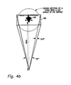
- Figure 4c reveals the field of view and beam coverage of a laser beam at a given range.
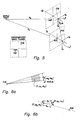
- Figure 5 shows the sensor geometry for two perspective views of the scene at two positions separated by a given distance.
- Figures 6a and 6b reveal two ways of computing the distances of interest or world points from the focus of expansion.
- Figure 7 reveals the geometry for calculating the range from an interest or world points viewed from two different frames of imagery.
- Figure 8 reveals an alternate approach for range calculation from an interest or world point from two frames of imagery.
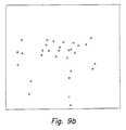
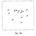
- Figures 9a, b, c and d show optical flow results of synthetic data for the invention.
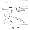
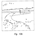
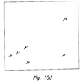
- Figures 10a, b, c and d show optical flow results using real data for the invention.
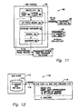
- Figure 11 reveals the hardware system for data collection for the invention.
- Figure 12 reveals a computer implementation of the invention.
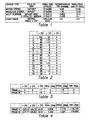
- Table 1 provides the parameters of the sensor suite of the invention.
- Table 2 gives the coordinates of synthetic interest or world points used in the application of the invention.
- Table 3 indicates the location, row, pitch, and yaw of the camera or sensor for two synthetic frames used in the application of the invention.
- Table 4 reveals the location, row, pitch, and yaw of the camera or sensor for two frames of real imagery in the invention.
- the present invention is maximally passive in that it combines data obtained from an inertial navigation sensor (INS) 26 with optical flow computations in inertial sensor integrated optical flow unit 18 of figure 1.
- INS inertial navigation sensor
- Figure 1 illustrates inertial sensors integrated optical flow unit 18 and scene analysis unit 20, incorporating context dependent image characterization and recognition of its components unit 12, range prediction and smoothing (using multiple frames) unit 14 and qualitative scene model and range calculations (to image pixels/symbols) unit 16, using selective application 24 of binocular stereo 54 (passive), laser radar 52 (active) ranging, motion stereo 56 and variable fields of view 57.
- the output is from range interpolation unit 28 which is connected to unit 16.
- inertial data from unit 26 into motion stereo 56 of unit 18 provides a robust approach.
- Traditional techniques suffer greatly from errors in the estimation of the location of the focus of expansion (FOE) and from errors in matching world points between frames.
- Inertial data enable unit 18 to compute the exact location of the FOE and remove the effect that sensor motion (i.e., roll, pitch and yaw) has upon the imagery; thus, the motion is effectively reduced to pure translation.
- sensor motion i.e., roll, pitch and yaw
- the task of world point matching is greatly simplified. The end result is that more world points are assigned matches from frame to frame and that the range measurements have improved accuracy.
- optical flow method 30 For a pair of image frames, the major steps of optical flow method 30 as shown in figure 2 begin with input frames, frame N-1 and frame N which are digitized video or FLIR images, being read in from passive sensors 22 along with units 32 and 34 wherein interest points are extracted from input frames N-1 and N. The extracted interest points are sent to interest point matcher 38 and interest point derotation unit 40, respectively.
- Location of the focus of expansion (FOE) (in both frames N-1 and N) is computed in FOE computational unit 36.
- Computational unit 36 output goes to interest point matcher 38.
- Inertial measurement unit 26 outputs rotational velocity information to derotational unit 40 and translational velocity information to FOE computational unit 36, range to interest points unit 42 and range interpolation over the entire area unit 44.
- FOE and the interest points in frame N are projected onto an image plane that is parallel to the image plane that captured frame N-1 (derotation of frame N).
- Interest points in frame N are matched to those of frame N-1 based upon four criteria.
- Range is computed to each interest point in frame N that has a match in frame N-1.
- a dense range map is created using context dependent scene analysis and interpolating between the computed range values.
- the imagery to system 30 is digitized and contains pixels addressed by row and column with the origin of 2-D coordinate system 48 of figure 3 located in the upper left corner of the image.
- the horizontal axis, c points to the right and the vertical axis, r, is in the downward direction.
- This image plane 46 is perpendicular to the x axis of 3-D coordinate system 50 and is located at a distance of the focal length F from the origin with the z axis in the downward direction. Therefore, the pixels in image plane 46 can be described in 2-D coordinate frame 48 as (c, r) and in 3-D coordinate frame 50 by the vector (F, y, z).
- the geometry described above is graphically illustrated in Figure 3.
- the data input to the obstacle detection method 30 consists of a sequence of digitized video or FLIR frames that are accompanied by inertial data consisting of rotational and translational velocities.
- This information coupled with the temporal sampling interval between frames, is used to compute the distance vector, , between each pair of frames and the roll, pitch and yaw angles, ( ⁇ , ⁇ , ⁇ ), of each frame. Both ⁇ d and ( ⁇ , ⁇ , ⁇ ) are crucial to method 30.
- the movement of the world points' (i.e., interest points') perspective projection (onto the image plane 46) is at a minimum near the FOE and, as a result, the range to the world or interest points nearest the FOE have the greatest amount of uncertainty associated with them.
- the passive ranging technique of binocular stereo 54 is most accurate near the center of the field of view (where the FOE is located most of the time) and is less accurate near the edges of the field of view.
- the binocular stereo 54 approach can function even when the vehicle is stopped or hovering.
- Wires and other small obstacles are detected by active sensor 52 and passive techniques 54 and 56 because of the greater resolution 57 ( Figure 1) and 64 ( Figure 4a) required to detect such obstacles at a range sufficient for obstacle avoidance.
- a trade-off is made between the field of view and resolution of the sensor(s). Since the system's field of view must be large enough such that the vehicle has sufficient (previously scanned) directions in which to steer when obstacles are detected, the field of view of the passive sensors can not be reduced; hence, laser range scanner 52 and a narrow FOV passive sensor function in conjunction with passive sensors 54 and 56 of system 10.
- the use of a simple (i.e., circular scanning) laser range sensor 52, whose scan pattern is centered around the FOE, is for the purpose of detecting only small obstacles that lie within the vehicle's direction of travel.
- Multipurpose passive sensor FOV 64 encompasses laser sensor FOV 62.
- Figure 4b illustrates the size of sensor FOV 66 which is required to detect obstacles at a range of 40 meters in the flight path of rotorcraft 68.
- a 0.5 milliradian (mrad) laser beam width having FOV 62 scans in circular pattern 70.
- Step size S used in scanning is 0.70 mrad (in the plane of scan circle 70), leading to 8,900 range samples in 2 p radians.
- the laser beam is 2 cm in diameter which leads to an overlap of the beam between samples.
- This overlap and small step size S result in 4 range samples being acquired, at the range of 40 meters, on a wire of 3 mm diameter which is perpendicular to the tangent to scanning circle 70.
- Laser range samples yield obstacle detections.
- the range values are compared to a minimum acceptable range threshold. World points having a range less than this threshold are a danger to the vehicle.
- Table 1 lists sensor types and typical parameters for FOV, array size, instantaneous FOV, and resolution.
- Each sensor and its function may be described, with emphasis on obstacle detection and avoidance in the context of rotorcraft navigation.
- sensor mountings those of gimbal controlled orientation and those of fixed orientation.
- Motion stereo sensor 56 which is of fixed orientation, is used to generate a sparse range map of world features over FOV 58.
- the wide FOV 58 is required for the sparse range map to provide suitable options for rotorcraft 68 maneuvering when an obstacle is encountered.
- Binocular stereo sensor 54 is used to provide range measurements over a medium FOV 60 that is centered within wide FOV 58 of motion stereo sensor 56.
- the purpose of binocular stereo sensor 54 is to provide range samples within the area where the motion stereo 56 measurements are the most error prone, around the instantaneous direction of vehicle heading (i.e., focus of expansion), which lies mainly within the center of FOV 58.
- the binocular stereo 54 measurements can be made when a vehicle is stationary (e.g., when rotorcraft 68 is hovering or when it is turning about its vertical axis without forward motion), thereby providing a range map which can be used to perform obstacle detection.
- Both the binocular 54 and motion 56 stereo sensors use TV or FLIR imagery to perform these measurements for day and night operations.
- Two kinds of sensors are mounted on a gimbaled platform --a variable FOV passive sensor (TV or FLIR) 22 and a scanning laser range finder 52. Placing the sensors on a gimbal allows their FOV's to be constantly focussed in the direction of rotorcraft travel, which is necessary since the sensors must be able to detect large and small obstacles (such as wires) which lie in the immediate path of the rotorcraft.
- Laser range finder 52 actively scans for obstacles and the passive sensor data are used to perform motion stereo 56 measurements or to simply extract two-dimensional (2-D) features which have a high probability of being obstacles (e.g., linear features of poles, wires, etc.).
- sensors' FOV's can be directed to an alternate flight corridor when obstacles are detected in the current corridor of the vehicle. Turning the sensors to the alternate corridor is necessary to determine the suitability of the corridor prior to executing a change in the flight path as part of the obstacle avoidance task.
- the alternate flight corridors are determined from the range measurements made by wide FOV fixed position sensors 56 and 54.
- the gimbaled sensors can be directed on a potential landing site for the purpose of obstacle detection prior to landing. In the air vehicle scenario, the gimbaled sensors may also be controlled by helmet mounted sensors.
- Wide FOV 58 of motion stereo sensor 56 is chosen to provide a wide, cleared area in which a lateral maneuver may be performed if an obstacle is detected.
- the vertical FOV is half of the horizontal FOV due to the nature of nap-of-the-Earth flight (in the air vehicle rotorcraft scenario) in which vertical maneuvers are not desired and lateral maneuvers are emphasized.
- Binocular stereo sensor 54 has a smaller, more conventional FOV 60 which is centered within motion stereo FOV 58 to compensate for range measurement error that occurs near the FOE in motion stereo measurements and to provide range measurements when the rotorcraft is not undergoing forward translation.
- the gimbaled sensors are designed to track the FOE of vehicle motion. Tracking the FOE with the high resolution passive and laser sensors provides the most accurate ranging techniques where they are needed most.
- the FOE is not the only location that needs to be sensed by the gimbaled sensors.
- the next step involves obstacle detection to be followed by obstacle avoidance.
- a model means a segmentation of the sensed image in which the various segments are labeled as to their respective types of terrain (sky, road, grass, etc.).
- Context dependent image characterization also called "scene analysis,” is applied to each frame, resulting in a model of the scene which aids in the identification of safe paths and aids the process of increasing the density of the range map.
- Interpolation of the range values obtained by the optical flow method of system 30 of figure 2 is aided by results of scene analyses. Having information about the scene allows for intelligent interpolation between the range values. For example, when range values fall on two trees separated by 25 meters of unobstructed space, the scene model can be used to prevent the range interpolation from connecting the trees and blocking off the space between them. The result is a more dense and accurate range map which can subsequently be used for obstacle avoidance.
- the features within the imagery (TV or FLIR) that are most prominent and distinguished, mark the world points to which range measurements will be made. These prominent world points, known as interest points, are easy to extract from the imagery and have the highest promise of repeated extraction throughout multiple frames.
- the interest points within the field-of-view of the monocular sensor are of fundamental and critical importance to optical flow calculations. The extraction and subsequent use of interest points are described below.
- Interest point selection involves computation of distinguishable points which is accomplished by passing a Moravec operator over each frame of imagery. The operator is applied to each image pixel (within a desired offset from the image border) which was identified as a strong edge pixel by a Sobel edge operator. The interest operator examines all pixels within a square window, of side length L, that surrounds each edge pixel and computes the relative variance between pixel values. As each pixel within the window is examined, the square of the difference between its value and the values of its neighboring pixels is computed and summed.
- Implementation of the Moravec operator ranks the detected interest points (pixels with a value of S which is a local maximum) in the order of their computed interestingness.
- This interest point extraction routine works on the segmented image obtained by context dependent scene analysis 12 ( Figure 1). Segmentation divides the image into M uniform regions. Interest point routine returns only the N points within each region which have the highest values of S, where N and M are inputs to the program. The result of returning only the best interest points (in terms of S) in each region is that the processed scene is intelligently covered with interest points. If this were not the case, a small number of occasionally adjacent regions will lay claim to the major portion of interest points.
- image characterization 12 is used to ascertain the goodness of regions prior to interest point selection.
- Interest point selection can be further improved by incorporation of Kalman filtering techniques, which use inertial sensor data to track and predict interesting point features.
- FIG. 5 is an illustration of the sensor geometry that records two perspective views of a scene at two positions separated by a distance
- ⁇ t
- the FOE and the projections of the world point are all colinear.
- derotation is performed for each vector, (F,y i ,z i ), that corresponds to each interest point in frame B.
- the equation for the derotation transformation and projection is: and where NED (north, east, down) is the coordinate frame in which inertial measurements are made. Use of the NED frame assumes that vehicle motion is ''local'' to a patch of Earth.
- the matrix C A NED converts points described in the NED coordinate frame into an equivalent description within a coordinate frame parallel to the A coordinate frame.
- the matrix C B NED converts the descriptions of points in the B coordinate frame into descriptions in a coordinate frame parallel to NED.
- the matching of interest points is performed in two passes.
- the goal of the first pass is to identify and store the top three candidate matches for each interest point in frame B, (F, y Bj ' z B j ).
- the second pass looks for multiple interest points being matched to a single point in frame A.
- the result of the second pass is a one-to-one match between the interest points in the two successive frames.
- a one-to-one match of interest points is necessary.
- the projection onto the sensor's image plane of an object in the world will grow in size as the sensor moves toward the object. This situation might imply that a one-to-one match is nonsensical since what was one pixel in size in frame A might become two or more pixels in size in frame B.
- the first pass is described in the following.
- the first metric makes certain that candidate matches lie within a cone shaped region bisected by the line joining the FOE and the interest point in frame B. This metric limits candidate matches to lie within the cone with apex at the FOE, as shown in Figure 6(a). If an interest point in frame A, (F,y Ai , z Ai ), passes the first metric, then the second metric is applied to it.
- the second metric requires that the interestingness of candidate matches is close to the interestingness of the point that we are trying to match. ( Figures 6a and 6b show constraints used to aid the process of matching interest points between frames.)
- the third metric restricts all candidate matches in frame A to lie closer to the FOE than the points of frame B (as physical laws would predict for stationary objects).
- This metric involves the computation of the distances of the interest points from the FOE, which can be computed in two different ways. The first is the direct euclidean distance, d1, between (F,y Ai , z Ai ) and (F,y Bj , z Bj ), and the second is the distance d2 which is the projection of d1 onto the line joining (F,y Bj , z Bj ) and the FOE.
- the distance measures are graphically illustrated in Figure 6(b). Regardless of the way that the distance measure is computed, it can be used to identify the closest candidate matches to (F,y Bj , z Bj ).
- the fourth metric constrains the distance between an interest point and its candidate matches. For an interest point in frame A, A j , to be a candidate match to point B j , it must lie within the shaded region of Figure 6(a). The depth of the region is determined by this fourth metric while the width of the region is fixed by an earlier metric.
- interest points, A j By limiting interest points, A j , to lie in the shaded region, one has effectively restricted the computed range of resulting matches to lie between R max and R min .
- the reasoning behind this restriction is that world objects of range less than R min should not occur due to autonomous or manual navigation of the vehicle, thus avoiding potential collisions. Likewise, objects at a range greater than R max are not yet of concern to the vehicle.
- the result of the first pass of interest point matching is a list, for each (F,y Bj , z Bj ), of three or fewer candidate matches that pass all metrics and have the smallest distance measures of all possible matches.
- the goal of the second pass of the matching process is to take the matches provided by the first pass and generate a one-to-one mapping between the interest points in frames A and B.
- the best match to (F,y Bj , z Bj ) will be the stored candidate match which has the smallest distance measure.
- the recorded list of best matches is searched for multiple occurrences of any of the interest points in frame A.
- the point, B* which is at the minimum distance from the A i in question, will retain this match and is removed from the matching process.
- the remaining B j's are returned to the matching process for further investigation after having A i removed from their lists of best matches. This process continues until all of the interest points in frame B either have a match, or are determined to be unmatchable by virtue of an empty candidate match list.
- the final result of the matching process is a one-to-one mapping between the interest points in frames A and B.
- range can be computed to each match.
- a range or obstacle map can be constructed.
- the obstacle map can take many forms, the simplest of which consists of a display of bearing versus range. The next step is range calculation and interpolation.
- Figure 7 shows the imaged world point in motion rather than the sensor, thereby simplifying the geometry.
- An alternate approach involves the calculation of the angles a A and a B between the translational velocity vector and the vectors that describe the matched pair of interest points in frames A and B, as indicated in Figure 8, wherein range calculation requires the computation of angles between the linear velocity vector and the vectors that describe the matched pair of interest points.
- Both of the range calculating techniques compute the distance to a world point relative to the lens center of frame A (similar equations would compute the distance from the lens center of frame B).
- the accuracy of the range measurements that result from either approach is very sensitive to the accuracy of the matching process as well as the accuracy of the inertial measurement unit (IMU) data.
- IMU inertial measurement unit
- the task of range interpolation is the last processing step required in the passive ranging system (excluding any postprocessing of the range that may be required before the processed data reaches the automatic vehicle control and display systems).
- range interpolation between the sparse range samples generated from the optical flow measurements, a dense range map representing the objects within the field of view is established.
- this task is surface fitting to a sparse, nonuniform set of data points.
- image segmentation, context dependent image characterizations and recognition of its components 12 Figure 1 are used to create regions from which a desired number of interest points are extracted.
- the type of surface fitting utilized is significant because the resulting surface (i.e., the range map) must pass through each of the range samples. It would be particularly detrimental if the surface passed under any range samples. Many techniques of surface fitting are applicable to the present task.
- range interpolation consists of a fitting of planes to the available range samples. This approach accomplishes the task efficiently and succeeds in passing through each range sample. Any technique of range interpolation needs to avoid interpolation over discontinuities that occur between range samples on the surface of concern. With scene analysis/segmentation, the smoothing of discontinuities is avoided by interpolating only over smooth regions or segments of the scene.
- Range computation (based on 2 frames) is further improved by estimating range over multiple frames.
- the procedure for prediction and smoothing of range using multiple frames 14 (Figure 1) is that for all interest points in a pair of images, compute matching confidence, measured and predicted ranges, confidence in range and threshold the result are computed to obtain the final range.
- I i x is the interestingness of ith point in frame X.
- d i is the projection of ith point (point A in Figure 6b) on the line connecting FOE with its match (point B in Figure 6b).
- Range confidence of ith point in frame n is given by the following set of equations.
- the inertial navigation sensor integrated optical flow method has been used to generate range samples using both synthetic data and real data (imagery and INS information) obtained from a moving vehicle.
- results are illustrated using a pair of frames.
- Synthetic interest points were generated from a file containing the 3-D coordinates of 15 world points.
- Table 2 shows the 3-D locations of these world points.
- table 3 lists the location, roll, pitch, and yaw of the camera at the two instances of time at which synthetic frames A and B were acquired. The time between frame acquisition is 0.2 seconds.
- Figures 9a, b, c and d show optical flow results of sythetic data.
- Figure 9a indicates the locations (circles) of the projection of the world (or interest) points onto the first location (i.e., first image) of the image plane where the field of view of the synthesized camera model is 52.0 degrees x 48.75 degrees with a focal length of 9 mm.
- Figure 9b shows the locations (squares) of the projections of the world (or interest) points onto the second location (i.e., second image) of the image plane and shows the new locations (diamonds) of those projections after derotation.
- Figure 9c shows the results of the matching process in which circles are connected to their corresponding diamond with a straight line and the FOE is labeled and marked with an X. In other words, the matching process results in displacement vectors between the circles and the diamonds.
- the final frame, Figure 9d shows the computed range value to each point resulting from each of the matches.
- FIG. 10a shows the locations of the extracted interest points obtained from the first frame, drawn as circles.
- Figure 10b indicates the location of extracted interest points (squares) and the corresponding derotated interest point locations (diamonds).
- FIG. 11 and 12 show the hardware system used for data collection by a ground vehicle and the ODIN system implementation.
- Figure 11 is a diagram of hardware system 80 for data collection for the motion field of view for obstacle detection system 10 of figure 1.
- VME chassis 82 (VME is an international standard bus) comprises central processing unit (CPU) 84 (model 68020) having serial port 86 and system clock 88 connected to CPU 84, an input/output proto board 90 connected to serial port 86 and system clock 88 of CPU 84, and DataCube (Boston, MA) hardware 92 that includes Digimax board 94 and MaxGraph board 96 which is connected to system clock 88.
- a Honeywell model 1050 ring laser gyroscope (RLG) inertial reference unit (IRU) is connected to I/O board 90 and provides inertial data with time stamping, which is collected at 50 Hz.
- Sensor 100 which is a Panasonic television camera, model WV-1850, having a focal length of 25 mm and an FOV of 20 degrees by 15 degrees, is connected to board 96 and provides imagery data.
- Output from chassis 82 goes to Panasonic optical disk recorder 102, model TQ-2023F.
- Recorder 102 is connected to serial port 86 and board 96.
- Video frames to recorder 102 have a time stamp and are recorded at 5 Hz sychronously with IRU data from inertial unit 98 to chassis 82.
- the data in recorder 102 are for optical flow unit 18 of figure 1.
- Figure 12 is hardware implementation 110 of obstacle detection system 10 of figure 1.
- Computer 112 (model Sun 3/280) receives television imagery and INS data.
- Data in recorder 102 of figure 11 go to disk 114 of computer 112.
- Data are in the form of 500 x 480 pixel images sampled at a 5 Hz rate.
- the INS data from unit 98 (from Honeywell 1050 RLG inertial measurement unit (IMU)) are in terms of latitude and longitude.
- Computer 12 is connected to computer 116 (model Sun 3/60) via ethernet 118.
- Computer 116 has a CPU, a math coprocessor and associated memory. It operates in C language in 4.2 BSD Unix (release 3.5) software.
- Computer 116 performs functions of system 10, particularly, units 18, 20, 24 and 28 of Figure 1.
Landscapes
- Engineering & Computer Science (AREA)
- Physics & Mathematics (AREA)
- Radar, Positioning & Navigation (AREA)
- Remote Sensing (AREA)
- General Physics & Mathematics (AREA)
- Electromagnetism (AREA)
- Computer Networks & Wireless Communication (AREA)
- Aviation & Aerospace Engineering (AREA)
- Automation & Control Theory (AREA)
- Length Measuring Devices By Optical Means (AREA)
- Traffic Control Systems (AREA)
Applications Claiming Priority (2)
| Application Number | Priority Date | Filing Date | Title |
|---|---|---|---|
| US459930 | 1983-01-21 | ||
| US07/459,930 US5128874A (en) | 1990-01-02 | 1990-01-02 | Inertial navigation sensor integrated obstacle detection system |
Publications (3)
| Publication Number | Publication Date |
|---|---|
| EP0436213A2 true EP0436213A2 (fr) | 1991-07-10 |
| EP0436213A3 EP0436213A3 (en) | 1991-11-06 |
| EP0436213B1 EP0436213B1 (fr) | 1995-08-02 |
Family
ID=23826737
Family Applications (1)
| Application Number | Title | Priority Date | Filing Date |
|---|---|---|---|
| EP90125447A Expired - Lifetime EP0436213B1 (fr) | 1990-01-02 | 1990-12-24 | Système de détection d'obstacle |
Country Status (3)
| Country | Link |
|---|---|
| US (1) | US5128874A (fr) |
| EP (1) | EP0436213B1 (fr) |
| DE (1) | DE69021354T2 (fr) |
Cited By (28)
| Publication number | Priority date | Publication date | Assignee | Title |
|---|---|---|---|---|
| DE4142097A1 (de) * | 1990-12-19 | 1992-07-16 | Mitsubishi Electric Corp | Abstandsmessgeraet mit bildaufnehmerfunktion |
| DE4222642A1 (de) * | 1992-07-10 | 1994-01-13 | Bodenseewerk Geraetetech | Bilderfassende Sensoreinheit |
| EP0631109A1 (fr) * | 1993-06-03 | 1994-12-28 | FINMECCANICA S.p.A., RAMO AZIENDALE ALENIA | Système de navigation à capteur d'images passif |
| EP0631111A1 (fr) * | 1993-06-22 | 1994-12-28 | AEROSPATIALE Société Nationale Industrielle | Procédé et dispositif pour déterminer la position d'un aéronef |
| WO2000022596A1 (fr) * | 1998-10-15 | 2000-04-20 | Consorzio C.R.E.O. - Centro Ricerche Elettro Ottiche | Systeme permettant d'eviter une collision de vehicules dans des conditions de visibilite faible |
| GB2362213A (en) * | 1997-07-14 | 2001-11-14 | British Aerospace | Inertial navigation accuracy enhancement |
| WO2004081598A2 (fr) | 2003-03-14 | 2004-09-23 | C.R.F. Società Consortile Per Azioni | Dispositif optoelectronique actif pour la detection d'obstacles, en particulier pour la navigation autonome |
| FR2886020A1 (fr) * | 2005-05-19 | 2006-11-24 | Eurocopter France | Systeme d'estimation de la vitesse d'un aeronef et son application a la detection d'obstacles |
| EP1681577A3 (fr) * | 2005-01-12 | 2008-08-20 | Robert Bosch Gmbh | Procédé destiné à la correction de la position d'image d'une image d'écran |
| WO2008146114A3 (fr) * | 2007-06-01 | 2009-03-05 | Toyota Motor Co Ltd | Dispositif de mesure, procédé de mesure, programme, et support lisible par ordinateur |
| EP1975646A3 (fr) * | 2007-03-28 | 2009-09-09 | Honeywell International Inc. | Évaluation de mouvement basé sur un chargeur pour navigation |
| WO2009115918A1 (fr) * | 2008-03-19 | 2009-09-24 | Toyota Jidosha Kabushiki Kaisha | Dispositif de détection d'objet |
| EP1711006A4 (fr) * | 2004-01-26 | 2010-01-20 | Nec Corp | Systeme d'evaluation du type video, systeme de traitement video, procede traitement video et programme de traitement video |
| EP2187233A1 (fr) * | 2008-11-12 | 2010-05-19 | Saab Ab | Dispositif d'estimation de portée |
| DE102009034026A1 (de) * | 2009-07-21 | 2011-01-27 | Bayerische Motoren Werke Aktiengesellschaft | Verfahren und Vorrichtung zur Erkennung von Objekten in der Umgebung eines Sensorsystems, insbesondere eines Sensorsystems eines Fahrzeugs |
| WO2011024116A3 (fr) * | 2009-08-30 | 2011-05-12 | Rafael Advanced Defense Systems Ltd. | Système et procédé d'évaluation de la distance virtuelle d'une cible |
| WO2013107561A1 (fr) * | 2012-01-18 | 2013-07-25 | Robert Bosch Gmbh | Obtention d'informations de profondeur à l'aide d'une mono-caméra montée dans un véhicule |
| EP2394247B1 (fr) * | 2009-02-06 | 2017-01-25 | Automotive Distance Control Systems GmbH | Procédé et dispositif de mise en oeuvre d'un système d'aide à la conduite par vidéo dans un véhicule |
| EP3276306A1 (fr) * | 2016-07-27 | 2018-01-31 | GE Aviation Systems LLC | Vehicule aerien sans pilote |
| CN108001457A (zh) * | 2016-10-28 | 2018-05-08 | 德尔福技术公司 | 自动车辆传感器控制系统 |
| US10126136B2 (en) | 2016-06-14 | 2018-11-13 | nuTonomy Inc. | Route planning for an autonomous vehicle |
| US10309792B2 (en) | 2016-06-14 | 2019-06-04 | nuTonomy Inc. | Route planning for an autonomous vehicle |
| US10331129B2 (en) | 2016-10-20 | 2019-06-25 | nuTonomy Inc. | Identifying a stopping place for an autonomous vehicle |
| US10473470B2 (en) | 2016-10-20 | 2019-11-12 | nuTonomy Inc. | Identifying a stopping place for an autonomous vehicle |
| US10681513B2 (en) | 2016-10-20 | 2020-06-09 | nuTonomy Inc. | Identifying a stopping place for an autonomous vehicle |
| US10857994B2 (en) | 2016-10-20 | 2020-12-08 | Motional Ad Llc | Identifying a stopping place for an autonomous vehicle |
| US11092446B2 (en) | 2016-06-14 | 2021-08-17 | Motional Ad Llc | Route planning for an autonomous vehicle |
| US11763555B2 (en) | 2021-04-22 | 2023-09-19 | Honeywell International Inc. | System and method for ground obstacle detection and database management |
Families Citing this family (91)
| Publication number | Priority date | Publication date | Assignee | Title |
|---|---|---|---|---|
| US5265172A (en) * | 1989-10-13 | 1993-11-23 | Texas Instruments Incorporated | Method and apparatus for producing optical flow using multi-spectral images |
| US5610815A (en) * | 1989-12-11 | 1997-03-11 | Caterpillar Inc. | Integrated vehicle positioning and navigation system, apparatus and method |
| US5390125A (en) * | 1990-02-05 | 1995-02-14 | Caterpillar Inc. | Vehicle position determination system and method |
| US5257209A (en) * | 1990-06-26 | 1993-10-26 | Texas Instruments Incorporated | Optical flow computation for moving sensors |
| IT1240974B (it) * | 1990-07-05 | 1993-12-27 | Fiat Ricerche | Metodo e apparecchiatura per evitare la collisione di un autoveicolo contro ostacoli. |
| JP2749727B2 (ja) * | 1991-03-08 | 1998-05-13 | 三菱電機株式会社 | 経路予測装置 |
| DE69209364T2 (de) * | 1991-05-22 | 1996-10-10 | Philips Electronics Nv | Verteiltes Mehrknoten-Datenverarbeitungssystem zur Verwendung in einem Oberflächenfahrzeug |
| US8352400B2 (en) | 1991-12-23 | 2013-01-08 | Hoffberg Steven M | Adaptive pattern recognition based controller apparatus and method and human-factored interface therefore |
| US10361802B1 (en) | 1999-02-01 | 2019-07-23 | Blanding Hovenweep, Llc | Adaptive pattern recognition based control system and method |
| US5461357A (en) * | 1992-01-29 | 1995-10-24 | Mazda Motor Corporation | Obstacle detection device for vehicle |
| DE4332612C2 (de) * | 1992-09-25 | 1996-02-22 | Yazaki Corp | Außenansichts-Überwachungsverfahren für Kraftfahrzeuge |
| IL104542A (en) * | 1993-01-28 | 1996-05-14 | Israel State | Airborne obstacle collision avoidance apparatus |
| DE4317960A1 (de) * | 1993-05-28 | 1995-01-12 | Bayerische Motoren Werke Ag | Verfahren zum Vermeiden einer Kollision eines Kraftfahrzeugs |
| US6542077B2 (en) | 1993-06-08 | 2003-04-01 | Raymond Anthony Joao | Monitoring apparatus for a vehicle and/or a premises |
| US7397363B2 (en) | 1993-06-08 | 2008-07-08 | Raymond Anthony Joao | Control and/or monitoring apparatus and method |
| US5917405A (en) | 1993-06-08 | 1999-06-29 | Joao; Raymond Anthony | Control apparatus and methods for vehicles |
| US5870179A (en) * | 1993-06-25 | 1999-02-09 | The Regents Of The University Of Colorado | Apparatus and method for estimating range |
| US6865477B2 (en) * | 1994-05-31 | 2005-03-08 | Winged Systems Corporation | High resolution autonomous precision positioning system |
| WO1996024216A1 (fr) | 1995-01-31 | 1996-08-08 | Transcenic, Inc. | Photographie referencee dans l'espace |
| US20020118457A1 (en) * | 2000-12-22 | 2002-08-29 | Dowski Edward Raymond | Wavefront coded imaging systems |
| US7218448B1 (en) * | 1997-03-17 | 2007-05-15 | The Regents Of The University Of Colorado | Extended depth of field optical systems |
| US6911638B2 (en) | 1995-02-03 | 2005-06-28 | The Regents Of The University Of Colorado, A Body Corporate | Wavefront coding zoom lens imaging systems |
| US20020195548A1 (en) * | 2001-06-06 | 2002-12-26 | Dowski Edward Raymond | Wavefront coding interference contrast imaging systems |
| US7253731B2 (en) | 2001-01-23 | 2007-08-07 | Raymond Anthony Joao | Apparatus and method for providing shipment information |
| US7277010B2 (en) | 1996-03-27 | 2007-10-02 | Raymond Anthony Joao | Monitoring apparatus and method |
| US6587046B2 (en) | 1996-03-27 | 2003-07-01 | Raymond Anthony Joao | Monitoring apparatus and method |
| US10152876B2 (en) | 1996-03-27 | 2018-12-11 | Gtj Ventures, Llc | Control, monitoring, and/or security apparatus and method |
| US10011247B2 (en) | 1996-03-27 | 2018-07-03 | Gtj Ventures, Llc | Control, monitoring and/or security apparatus and method |
| US7268700B1 (en) | 1998-01-27 | 2007-09-11 | Hoffberg Steven M | Mobile communication device |
| US9075136B1 (en) | 1998-03-04 | 2015-07-07 | Gtj Ventures, Llc | Vehicle operator and/or occupant information apparatus and method |
| JPH11353565A (ja) * | 1998-06-09 | 1999-12-24 | Yazaki Corp | 車両用衝突警報方法及び装置 |
| US6021373A (en) * | 1998-12-21 | 2000-02-01 | Eaton Corporation | Back-up proximity sensor for a vehicle |
| US7966078B2 (en) | 1999-02-01 | 2011-06-21 | Steven Hoffberg | Network media appliance system and method |
| US7003134B1 (en) * | 1999-03-08 | 2006-02-21 | Vulcan Patents Llc | Three dimensional object pose estimation which employs dense depth information |
| JP2001213254A (ja) * | 2000-01-31 | 2001-08-07 | Yazaki Corp | 車両用側方監視装置 |
| US6411898B2 (en) * | 2000-04-24 | 2002-06-25 | Matsushita Electric Industrial Co., Ltd. | Navigation device |
| JP2001344597A (ja) * | 2000-05-30 | 2001-12-14 | Fuji Heavy Ind Ltd | 融合視界装置 |
| US6502053B1 (en) * | 2000-06-12 | 2002-12-31 | Larry Hardin | Combination passive and active speed detection system |
| US6536898B1 (en) * | 2000-09-15 | 2003-03-25 | The Regents Of The University Of Colorado | Extended depth of field optics for human vision |
| JP3679988B2 (ja) * | 2000-09-28 | 2005-08-03 | 株式会社東芝 | 画像処理装置及び画像処理方法 |
| US6873733B2 (en) | 2001-01-19 | 2005-03-29 | The Regents Of The University Of Colorado | Combined wavefront coding and amplitude contrast imaging systems |
| US6940994B2 (en) * | 2001-03-09 | 2005-09-06 | The Boeing Company | Passive power line detection system for aircraft |
| JP4162910B2 (ja) * | 2001-05-11 | 2008-10-08 | 本田技研工業株式会社 | 接近検出装置、接近検出方法、及び接近検出プログラム |
| DE10154861A1 (de) * | 2001-11-08 | 2003-05-22 | Ibeo Automobile Sensor Gmbh | Verfahren zur Bereitstellung von Bildinformationen |
| DE50212810D1 (de) | 2001-06-15 | 2008-11-06 | Ibeo Automobile Sensor Gmbh | Korrekturverfahren für daten mehrerer optoelektronischer sensoren |
| US6842297B2 (en) | 2001-08-31 | 2005-01-11 | Cdm Optics, Inc. | Wavefront coding optics |
| US20030076981A1 (en) * | 2001-10-18 | 2003-04-24 | Smith Gregory Hugh | Method for operating a pre-crash sensing system in a vehicle having a counter-measure system |
| US10562492B2 (en) | 2002-05-01 | 2020-02-18 | Gtj Ventures, Llc | Control, monitoring and/or security apparatus and method |
| AU2003225228A1 (en) | 2002-05-03 | 2003-11-17 | Donnelly Corporation | Object detection system for vehicle |
| US7006709B2 (en) * | 2002-06-15 | 2006-02-28 | Microsoft Corporation | System and method deghosting mosaics using multiperspective plane sweep |
| US9818136B1 (en) | 2003-02-05 | 2017-11-14 | Steven M. Hoffberg | System and method for determining contingent relevance |
| DE10312249A1 (de) * | 2003-03-19 | 2004-09-30 | Ibeo Automobile Sensor Gmbh | Verfahren zur gemeinsamen Verarbeitung von tiefenaufgelösten Bildern und Videobildern |
| CN1714275B (zh) * | 2003-07-16 | 2012-02-22 | 哈曼贝克自动系统股份有限公司 | 导航系统及在导航系统中确定路线的方法 |
| JP2005078528A (ja) * | 2003-09-02 | 2005-03-24 | Honda Motor Co Ltd | 物体検出装置及び方法 |
| US7916898B2 (en) * | 2003-09-15 | 2011-03-29 | Deere & Company | Method and system for identifying an edge of a crop |
| DE10358017A1 (de) * | 2003-12-11 | 2005-07-21 | Siemens Ag | 3D Kamerasteuerung |
| JP2008501955A (ja) * | 2004-06-02 | 2008-01-24 | アテナ テクノロジーズ,インコーポレーテッド | イメージ拡張型の慣性航行システム(iains)および方法 |
| US7720580B2 (en) | 2004-12-23 | 2010-05-18 | Donnelly Corporation | Object detection system for vehicle |
| US7301497B2 (en) * | 2005-04-05 | 2007-11-27 | Eastman Kodak Company | Stereo display for position sensing systems |
| US20070233353A1 (en) * | 2006-03-28 | 2007-10-04 | Alexander Kade | Enhanced adaptive cruise control system with forward vehicle collision mitigation |
| US20080077284A1 (en) * | 2006-04-19 | 2008-03-27 | Swope John M | System for position and velocity sense of an aircraft |
| US8686326B1 (en) * | 2008-03-26 | 2014-04-01 | Arete Associates | Optical-flow techniques for improved terminal homing and control |
| EP2159779B1 (fr) * | 2008-08-27 | 2013-01-16 | Saab Ab | Utilisation d'un capteur d'images et d'un filtre de suivi de temps restant pour éviter les collisions dans l'espace |
| DE102009050368A1 (de) | 2008-10-24 | 2010-05-27 | Magna Electronics Europe Gmbh & Co.Kg | Verfahren zum automatischen Kalibrieren einer virtuellen Kamera |
| US8964032B2 (en) * | 2009-01-30 | 2015-02-24 | Magna Electronics Inc. | Rear illumination system |
| DE102009038406B4 (de) * | 2009-08-24 | 2017-10-05 | Volkswagen Ag | Verfahren und Vorrichtung zur Vermessung des Umfeldes eines Kraftfahrzeugs |
| US8239130B1 (en) | 2009-11-12 | 2012-08-07 | Google Inc. | Enhanced identification of interesting points-of-interest |
| US8774527B1 (en) | 2009-12-07 | 2014-07-08 | Google Inc. | Matching an approximately located query image against a reference image set using cellular base station and wireless access point information |
| US8189964B2 (en) | 2009-12-07 | 2012-05-29 | Google Inc. | Matching an approximately located query image against a reference image set |
| US9547910B2 (en) * | 2010-03-04 | 2017-01-17 | Honeywell International Inc. | Method and apparatus for vision aided navigation using image registration |
| US8922648B2 (en) * | 2010-08-26 | 2014-12-30 | Honda Motor Co., Ltd. | Rotation cancellation for moving obstacle detection |
| US20160071281A1 (en) * | 2012-12-12 | 2016-03-10 | Giovanni Cordara | Method and apparatus for segmentation of 3d image data |
| WO2014090303A1 (fr) | 2012-12-12 | 2014-06-19 | Huawei Technologies Co., Ltd. | Procédé et appareil pour la segmentation de données d'image en 3d |
| US10546441B2 (en) | 2013-06-04 | 2020-01-28 | Raymond Anthony Joao | Control, monitoring, and/or security, apparatus and method for premises, vehicles, and/or articles |
| US9669940B1 (en) * | 2013-06-27 | 2017-06-06 | Rockwell Collins, Inc. | Latency-reducing image generating system, device, and method |
| WO2016114828A2 (fr) * | 2014-10-20 | 2016-07-21 | Bae Systems Information And Electronic Systems Integration Inc. | Modélisation d'évaluation de distance avec stabilisation par inertie |
| EP3283843B1 (fr) | 2015-04-01 | 2024-01-10 | Vayavision Sensing Ltd. | Génération de cartes en trois dimensions d'une scène à l'aide de mesures passives et actives |
| CN105005999B (zh) * | 2015-08-12 | 2018-08-10 | 北京航空航天大学 | 一种基于计算机立体视觉面向导盲仪的障碍物探测方法 |
| CN106483578B (zh) * | 2016-11-25 | 2019-03-29 | 同方威视技术股份有限公司 | 移动式扫描检测系统 |
| US10445928B2 (en) | 2017-02-11 | 2019-10-15 | Vayavision Ltd. | Method and system for generating multidimensional maps of a scene using a plurality of sensors of various types |
| CN107909010B (zh) * | 2017-10-27 | 2022-03-18 | 北京中科慧眼科技有限公司 | 一种道路障碍物检测方法与装置 |
| US11067686B2 (en) * | 2017-12-01 | 2021-07-20 | Electromagnetic Systems, Inc. | Obstacle position and extent measurement by automotive radar |
| CN110542415A (zh) * | 2018-05-28 | 2019-12-06 | 北京京东尚科信息技术有限公司 | 用于导航系统的导航方法和装置 |
| US11835948B2 (en) | 2018-12-03 | 2023-12-05 | Motional Ad Llc | Systems and methods for improving vehicle operations using movable sensors |
| CN109631887B (zh) * | 2018-12-29 | 2022-10-18 | 重庆邮电大学 | 基于双目、加速度与陀螺仪的惯性导航高精度定位方法 |
| US11367211B2 (en) | 2019-07-29 | 2022-06-21 | Raytheon Company | Inertially-assisted target detection |
| CN111150330B (zh) * | 2019-12-30 | 2024-12-10 | 深圳腾跃信息科技服务有限公司 | 清扫控制方法 |
| WO2022016276A1 (fr) | 2020-07-21 | 2022-01-27 | Leddartech Inc. | Dispositif d'orientation de faisceau, en particulier pour systèmes lidar |
| US11422266B2 (en) | 2020-07-21 | 2022-08-23 | Leddartech Inc. | Beam-steering devices and methods for LIDAR applications |
| WO2022016277A1 (fr) | 2020-07-21 | 2022-01-27 | Leddartech Inc. | Systèmes et procédés pour lidar grand angle faisant appel à une optique de grossissement non uniforme |
| EP4293311A1 (fr) * | 2022-06-14 | 2023-12-20 | 21strategies GmbH | Dispositif de commande d'un système d'arme et système d'arme |
Family Cites Families (15)
| Publication number | Priority date | Publication date | Assignee | Title |
|---|---|---|---|---|
| US3421716A (en) * | 1962-11-13 | 1969-01-14 | Goodyear Aerospace Corp | Vehicle guidance system |
| US3404398A (en) * | 1967-06-12 | 1968-10-01 | North American Rockwell | Terrain following system employing intermittent radiation |
| US4264907A (en) * | 1968-04-17 | 1981-04-28 | General Dynamics Corporation, Pomona Division | Rolling dual mode missile |
| US3713147A (en) * | 1970-12-23 | 1973-01-23 | United Aircraft Corp | Obstacle detection with crossed fan beam |
| US4495580A (en) * | 1981-03-30 | 1985-01-22 | E-Systems, Inc. | Navigation system |
| GB2115633B (en) * | 1982-02-22 | 1985-07-10 | Secr Defence | Low level flying aids |
| US4497065A (en) * | 1982-07-12 | 1985-01-29 | Westinghouse Electric Corp. | Target recognition system enhanced by active signature measurements |
| US4700307A (en) * | 1983-07-11 | 1987-10-13 | General Dynamics Corp./Convair Division | Feature navigation system and method |
| US4635203A (en) * | 1984-04-06 | 1987-01-06 | Honeywell Inc. | Passive range measurement apparatus and method |
| US4695959A (en) * | 1984-04-06 | 1987-09-22 | Honeywell Inc. | Passive range measurement apparatus and method |
| JPS62155140A (ja) * | 1985-12-27 | 1987-07-10 | Aisin Warner Ltd | 車両制御用道路画像入力方式 |
| IT1202534B (it) * | 1987-02-13 | 1989-02-09 | Tecnomare Spa | Apparecchiatura per il rilevamento in continuo della distanza da essa di un punto prefissato,anche mobile |
| JP2570315B2 (ja) * | 1987-09-01 | 1997-01-08 | アイシン精機株式会社 | 車上距離検出装置 |
| US4872051A (en) * | 1987-10-01 | 1989-10-03 | Environmental Research Institute Of Michigan | Collision avoidance alarm system |
| US4954837A (en) * | 1989-07-20 | 1990-09-04 | Harris Corporation | Terrain aided passive range estimation |
-
1990
- 1990-01-02 US US07/459,930 patent/US5128874A/en not_active Expired - Lifetime
- 1990-12-24 DE DE69021354T patent/DE69021354T2/de not_active Expired - Fee Related
- 1990-12-24 EP EP90125447A patent/EP0436213B1/fr not_active Expired - Lifetime
Cited By (45)
| Publication number | Priority date | Publication date | Assignee | Title |
|---|---|---|---|---|
| DE4142097A1 (de) * | 1990-12-19 | 1992-07-16 | Mitsubishi Electric Corp | Abstandsmessgeraet mit bildaufnehmerfunktion |
| DE4142097B4 (de) * | 1990-12-19 | 2004-01-29 | Mitsubishi Denki K.K. | Abstandsmeßgerät |
| US5528354A (en) * | 1992-07-10 | 1996-06-18 | Bodenseewerk Geratetechnik Gmbh | Picture detecting sensor unit |
| DE4222642A1 (de) * | 1992-07-10 | 1994-01-13 | Bodenseewerk Geraetetech | Bilderfassende Sensoreinheit |
| EP0631109A1 (fr) * | 1993-06-03 | 1994-12-28 | FINMECCANICA S.p.A., RAMO AZIENDALE ALENIA | Système de navigation à capteur d'images passif |
| EP0631111A1 (fr) * | 1993-06-22 | 1994-12-28 | AEROSPATIALE Société Nationale Industrielle | Procédé et dispositif pour déterminer la position d'un aéronef |
| FR2707001A1 (fr) * | 1993-06-22 | 1994-12-30 | Aerospatiale | |
| GB2362213A (en) * | 1997-07-14 | 2001-11-14 | British Aerospace | Inertial navigation accuracy enhancement |
| GB2362213B (en) * | 1997-07-14 | 2002-02-27 | British Aerospace | Inertial navigation accuracy enhancement |
| US6912464B1 (en) | 1997-07-14 | 2005-06-28 | Bae Systems Plc | Inertial navigation accuracy enhancement |
| WO2000022596A1 (fr) * | 1998-10-15 | 2000-04-20 | Consorzio C.R.E.O. - Centro Ricerche Elettro Ottiche | Systeme permettant d'eviter une collision de vehicules dans des conditions de visibilite faible |
| WO2004081598A2 (fr) | 2003-03-14 | 2004-09-23 | C.R.F. Società Consortile Per Azioni | Dispositif optoelectronique actif pour la detection d'obstacles, en particulier pour la navigation autonome |
| US7202459B2 (en) | 2003-03-14 | 2007-04-10 | C.R.F. Societa Consortile Per Azioni | Active electro-optical device for detecting obstacles, in particular for autonomous navigation |
| EP1711006A4 (fr) * | 2004-01-26 | 2010-01-20 | Nec Corp | Systeme d'evaluation du type video, systeme de traitement video, procede traitement video et programme de traitement video |
| US7730814B2 (en) | 2004-01-26 | 2010-06-08 | Nec Corporation | Video image type determination system, video image processing system, video image processing method and video image processing program |
| EP1681577A3 (fr) * | 2005-01-12 | 2008-08-20 | Robert Bosch Gmbh | Procédé destiné à la correction de la position d'image d'une image d'écran |
| US7791529B2 (en) | 2005-05-19 | 2010-09-07 | Eurocopter | System for estimating the speed of an aircraft, and an application thereof to detecting obstacles |
| FR2886020A1 (fr) * | 2005-05-19 | 2006-11-24 | Eurocopter France | Systeme d'estimation de la vitesse d'un aeronef et son application a la detection d'obstacles |
| EP1975646A3 (fr) * | 2007-03-28 | 2009-09-09 | Honeywell International Inc. | Évaluation de mouvement basé sur un chargeur pour navigation |
| WO2008146114A3 (fr) * | 2007-06-01 | 2009-03-05 | Toyota Motor Co Ltd | Dispositif de mesure, procédé de mesure, programme, et support lisible par ordinateur |
| US8295643B2 (en) | 2007-06-01 | 2012-10-23 | Toyota Jidosha Kabushiki Kaisha | Device and associated methodology for measuring three-dimensional positions based on retrieved points from one view angle and positions and postures from another view angle |
| WO2009115918A1 (fr) * | 2008-03-19 | 2009-09-24 | Toyota Jidosha Kabushiki Kaisha | Dispositif de détection d'objet |
| EP2187233A1 (fr) * | 2008-11-12 | 2010-05-19 | Saab Ab | Dispositif d'estimation de portée |
| US8588998B2 (en) | 2008-11-12 | 2013-11-19 | Saab Ab | Range estimation device |
| EP2394247B1 (fr) * | 2009-02-06 | 2017-01-25 | Automotive Distance Control Systems GmbH | Procédé et dispositif de mise en oeuvre d'un système d'aide à la conduite par vidéo dans un véhicule |
| DE102009034026A1 (de) * | 2009-07-21 | 2011-01-27 | Bayerische Motoren Werke Aktiengesellschaft | Verfahren und Vorrichtung zur Erkennung von Objekten in der Umgebung eines Sensorsystems, insbesondere eines Sensorsystems eines Fahrzeugs |
| US20120176494A1 (en) * | 2009-08-30 | 2012-07-12 | Yishay Kamon | System and method for virtual range estimation |
| WO2011024116A3 (fr) * | 2009-08-30 | 2011-05-12 | Rafael Advanced Defense Systems Ltd. | Système et procédé d'évaluation de la distance virtuelle d'une cible |
| WO2013107561A1 (fr) * | 2012-01-18 | 2013-07-25 | Robert Bosch Gmbh | Obtention d'informations de profondeur à l'aide d'une mono-caméra montée dans un véhicule |
| US11092446B2 (en) | 2016-06-14 | 2021-08-17 | Motional Ad Llc | Route planning for an autonomous vehicle |
| US11022449B2 (en) | 2016-06-14 | 2021-06-01 | Motional Ad Llc | Route planning for an autonomous vehicle |
| US10126136B2 (en) | 2016-06-14 | 2018-11-13 | nuTonomy Inc. | Route planning for an autonomous vehicle |
| US10309792B2 (en) | 2016-06-14 | 2019-06-04 | nuTonomy Inc. | Route planning for an autonomous vehicle |
| US11022450B2 (en) | 2016-06-14 | 2021-06-01 | Motional Ad Llc | Route planning for an autonomous vehicle |
| US10474148B2 (en) | 2016-07-27 | 2019-11-12 | General Electric Company | Navigating an unmanned aerial vehicle |
| EP3276306A1 (fr) * | 2016-07-27 | 2018-01-31 | GE Aviation Systems LLC | Vehicule aerien sans pilote |
| US10857994B2 (en) | 2016-10-20 | 2020-12-08 | Motional Ad Llc | Identifying a stopping place for an autonomous vehicle |
| US10681513B2 (en) | 2016-10-20 | 2020-06-09 | nuTonomy Inc. | Identifying a stopping place for an autonomous vehicle |
| US10473470B2 (en) | 2016-10-20 | 2019-11-12 | nuTonomy Inc. | Identifying a stopping place for an autonomous vehicle |
| US10331129B2 (en) | 2016-10-20 | 2019-06-25 | nuTonomy Inc. | Identifying a stopping place for an autonomous vehicle |
| US11711681B2 (en) | 2016-10-20 | 2023-07-25 | Motional Ad Llc | Identifying a stopping place for an autonomous vehicle |
| EP3318893A1 (fr) * | 2016-10-28 | 2018-05-09 | Delphi Technologies, Inc. | Système de commande de capteur de véhicule automatisé |
| CN108001457A (zh) * | 2016-10-28 | 2018-05-08 | 德尔福技术公司 | 自动车辆传感器控制系统 |
| CN108001457B (zh) * | 2016-10-28 | 2022-06-10 | 动态Ad有限责任公司 | 自动车辆传感器控制系统 |
| US11763555B2 (en) | 2021-04-22 | 2023-09-19 | Honeywell International Inc. | System and method for ground obstacle detection and database management |
Also Published As
| Publication number | Publication date |
|---|---|
| US5128874A (en) | 1992-07-07 |
| DE69021354T2 (de) | 1996-03-28 |
| DE69021354D1 (de) | 1995-09-07 |
| EP0436213A3 (en) | 1991-11-06 |
| EP0436213B1 (fr) | 1995-08-02 |
Similar Documents
| Publication | Publication Date | Title |
|---|---|---|
| EP0436213B1 (fr) | Système de détection d'obstacle | |
| CN113485441B (zh) | 结合无人机高精度定位和视觉跟踪技术的配网巡检方法 | |
| EP0896267B1 (fr) | Système de reconnaissance de la position d'un véhicule se déplaçant de manière autonome | |
| Amidi et al. | A visual odometer for autonomous helicopter flight | |
| US9070289B2 (en) | System and method for detecting, tracking and estimating the speed of vehicles from a mobile platform | |
| US9025825B2 (en) | System and method for visual motion based object segmentation and tracking | |
| US5564650A (en) | Processor arrangement | |
| Chellappa et al. | On the positioning of multisensor imagery for exploitation and target recognition | |
| CN116508071A (zh) | 用于注释汽车雷达数据的系统和方法 | |
| Bhanu et al. | Inertial navigation sensor integrated motion analysis for obstacle detection | |
| Bhanu et al. | A system for obstacle detection during rotorcraft low altitude flight | |
| Singh et al. | Autonomous cross-country navigation using stereo vision | |
| Sasa et al. | Position and attitude estimation using image processing of runway | |
| CA2025971C (fr) | Systeme de detection d'obstacles a senseur de navigation intertiel | |
| Roberts et al. | Inertial navigation sensor integrated motion analysis for autonomous vehicle navigation | |
| CN114322943B (zh) | 一种基于无人机前视图像的目标距离测量方法及装置 | |
| Kang et al. | Development of a peripheral-central vision system for small UAS tracking | |
| Sridhar et al. | Vision‐based obstacle detection for rotorcraft flight | |
| RU2853445C1 (ru) | Способ автономного определения местоположения маловысотного летательного аппарата по информации от одной камеры, инерциального измерительного модуля и опорных спутниковых снимков местности | |
| Niedfeldt et al. | Integrated sensor guidance using probability of object identification | |
| Collins et al. | Targeting for future weapon systems | |
| Roberts et al. | 3660 Technology Drive | |
| Ulvklo et al. | A sensor management framework for autonomous UAV surveillance | |
| Wang et al. | Research on visual odometry based on large-scale aerial images taken by UAV | |
| Tang et al. | Model-based approach for detection of objects in low-resolution passive-millimeter images |
Legal Events
| Date | Code | Title | Description |
|---|---|---|---|
| PUAI | Public reference made under article 153(3) epc to a published international application that has entered the european phase |
Free format text: ORIGINAL CODE: 0009012 |
|
| AK | Designated contracting states |
Kind code of ref document: A2 Designated state(s): DE FR GB |
|
| PUAL | Search report despatched |
Free format text: ORIGINAL CODE: 0009013 |
|
| AK | Designated contracting states |
Kind code of ref document: A3 Designated state(s): DE FR GB |
|
| 17P | Request for examination filed |
Effective date: 19920422 |
|
| 17Q | First examination report despatched |
Effective date: 19940209 |
|
| GRAA | (expected) grant |
Free format text: ORIGINAL CODE: 0009210 |
|
| AK | Designated contracting states |
Kind code of ref document: B1 Designated state(s): DE FR GB |
|
| REF | Corresponds to: |
Ref document number: 69021354 Country of ref document: DE Date of ref document: 19950907 |
|
| ET | Fr: translation filed | ||
| PLBE | No opposition filed within time limit |
Free format text: ORIGINAL CODE: 0009261 |
|
| STAA | Information on the status of an ep patent application or granted ep patent |
Free format text: STATUS: NO OPPOSITION FILED WITHIN TIME LIMIT |
|
| 26N | No opposition filed | ||
| REG | Reference to a national code |
Ref country code: GB Ref legal event code: IF02 |
|
| PGFP | Annual fee paid to national office [announced via postgrant information from national office to epo] |
Ref country code: FR Payment date: 20081205 Year of fee payment: 19 |
|
| PGFP | Annual fee paid to national office [announced via postgrant information from national office to epo] |
Ref country code: DE Payment date: 20081230 Year of fee payment: 19 |
|
| PGFP | Annual fee paid to national office [announced via postgrant information from national office to epo] |
Ref country code: GB Payment date: 20081110 Year of fee payment: 19 |
|
| GBPC | Gb: european patent ceased through non-payment of renewal fee |
Effective date: 20091224 |
|
| REG | Reference to a national code |
Ref country code: FR Ref legal event code: ST Effective date: 20100831 |
|
| PG25 | Lapsed in a contracting state [announced via postgrant information from national office to epo] |
Ref country code: FR Free format text: LAPSE BECAUSE OF NON-PAYMENT OF DUE FEES Effective date: 20091231 |
|
| PG25 | Lapsed in a contracting state [announced via postgrant information from national office to epo] |
Ref country code: DE Free format text: LAPSE BECAUSE OF NON-PAYMENT OF DUE FEES Effective date: 20100701 |
|
| PG25 | Lapsed in a contracting state [announced via postgrant information from national office to epo] |
Ref country code: GB Free format text: LAPSE BECAUSE OF NON-PAYMENT OF DUE FEES Effective date: 20091224 |
|
| P01 | Opt-out of the competence of the unified patent court (upc) registered |
Effective date: 20230525 |