EP0436242A1 - Verfahren zur Untersuchung und Kontrolle eines Flüssigkeitszuflusses während des Bohrens eines Bohrloches - Google Patents
Verfahren zur Untersuchung und Kontrolle eines Flüssigkeitszuflusses während des Bohrens eines Bohrloches Download PDFInfo
- Publication number
- EP0436242A1 EP0436242A1 EP90203119A EP90203119A EP0436242A1 EP 0436242 A1 EP0436242 A1 EP 0436242A1 EP 90203119 A EP90203119 A EP 90203119A EP 90203119 A EP90203119 A EP 90203119A EP 0436242 A1 EP0436242 A1 EP 0436242A1
- Authority
- EP
- European Patent Office
- Prior art keywords
- mud
- pressure
- time
- influx
- determined
- Prior art date
- Legal status (The legal status is an assumption and is not a legal conclusion. Google has not performed a legal analysis and makes no representation as to the accuracy of the status listed.)
- Granted
Links
Images
Classifications
-
- E—FIXED CONSTRUCTIONS
- E21—EARTH OR ROCK DRILLING; MINING
- E21B—EARTH OR ROCK DRILLING; OBTAINING OIL, GAS, WATER, SOLUBLE OR MELTABLE MATERIALS OR A SLURRY OF MINERALS FROM WELLS
- E21B49/00—Testing the nature of borehole walls; Formation testing; Methods or apparatus for obtaining samples of soil or well fluids, specially adapted to earth drilling or wells
- E21B49/005—Testing the nature of borehole walls or the formation by using drilling mud or cutting data
-
- E—FIXED CONSTRUCTIONS
- E21—EARTH OR ROCK DRILLING; MINING
- E21B—EARTH OR ROCK DRILLING; OBTAINING OIL, GAS, WATER, SOLUBLE OR MELTABLE MATERIALS OR A SLURRY OF MINERALS FROM WELLS
- E21B21/00—Methods or apparatus for flushing boreholes, e.g. by use of exhaust air from motor
- E21B21/08—Controlling or monitoring pressure or flow of drilling fluid, e.g. automatic filling of boreholes, automatic control of bottom pressure
Definitions
- the invention relates to a method of analysis and control, in real time, of a fluid influx into a hydrocarbon well which occurs during drilling.
- a fluid influx into a hydrocarbon well which occurs during drilling.
- the formation fluid can be safely circulated out and the mud then weighted to enable drilling to continue without danger.
- the formation fluid that has entered the well is a liquid (brine or hydrocarbons, for example)
- the circulation of this fluid does not present any specific problems, since this fluid scarcely increases in volume during its rise to the surface and, therefore, the hydrostatic pressure exercised by the drilling mud at the bottom of the well remains more or less constant.
- the formation fluid is gaseous, it expands on rising and this creates a problem in that the hydrostatic pressure gradually decreases.
- the usual means of analysis and control available to the driller comprise the mud level in the mud tank, the mud injection pressure into the drill pipes, and the well annulus surface pressure. These three data allow the driller to calculate the volume and nature of the influx, and also the formation pressure. It is on this information that he bases his influx circulation programme.
- the influx density calculations thus often lead to the conclusion that the influx is a mixture of gas and liquid (oil or water) whereas it may in fact be a gas or a liquid only. It should also be noted that this calculation can not be made when the influx is in a horizontal part of the well.
- the methods of the prior art are often not sufficiently accurate to allow a correct determination of the parameters characterizing the influx and the well conditions.
- the precise time to open the choke valve in order to control the well is either not described or predicted as being later than necessary.
- the present invention offers a method of deriving the required information to analyse and control a fluid influx in a borehole from an analysis of the surface inlet or outlet pressure monitored on a continuous basis when the well is shut-in and operating the choke valve at the right time and in the correct manner.
- the proposed method may be applied in deviated and even horizontal wells.
- the invention relates to a method of real time analysis and control of a fluid influx from an underground formation into a wellbore being drilled with a drill string, a drilling mud circulating from the surface down to the bottomhole into the drill string and flowing back to the surface in the annulus defined between the wall of the wellbore and the drill string, therein the well is shut-in when the influx is detected and therein the mud pressure, which is the outlet pressure p o and/or the inlet pressure p i of the drilling mud, is measured as a function of time at the surface, the method further comprising the steps of determining, from the increase of the mud pressure measurement, the time t c corresponding to the minimum gradient in the increase of the mud pressure and controlling the well from said time t c .
- time t c corresponds to the time when the inlet pressure p i is substantially equal to the difference between the formation pressure p f and the hydrostatic pressure p H created by the density of the drilling mud.
- the formation pressure p f is derived by adding the inlet pressure p i at time t c to the hydrostatic pressure p H .
- the rate of change dp i of the inlet pressure p i is monitored at time t c , said rate of change being compared with a predetermined value, and the type of influx is determined from said comparison.
- the volume and the density of the influx can be derived from the determination of time t c .
- the invention applies as well to analysis based on continuously monitored outlet pressure p o .
- outlet pressure For illustrative purposes only the inlet pressure will be mentioned from now on.
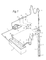
- Figure 1 shows schematically the drilling mud circuit of a well during control of an influx.
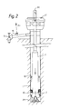
- Figure 2 shows in diagram form the hydraulic circuit of a well during control of a gas influx.
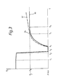
- Figure 3 shows an example of inlet pressure p i as a function of time, as predicted by the prior art and as observed during a numerical simulation of a gas kick, in accordance with the present invention.
- Figure 1 shows the mud circuit of a well 1 during a formation fluid influx control operation.
- the bit 2 is attached to the end of a drill string 3.
- the mud circuit comprises a tank 4 containing drilling mud 5, a pump (or several pumps) 6 sucking mud from the tank 4 through a pipe 7 and discharging it into the well 1, through a rigid pipe 8 and flexible hose 9 connected to the tubular drill string 3 via a swivel 17.
- the mud escapes from the drill string when it reaches the bit 2 and returns up the well through the annulus 10 between the drill string and the well wall.
- the drilling mud flows through a blow-out preventer 12, which is open, into the mud tank 4 through a line 24 and through a vibratory screen not shown in the diagram to separate the cuttings from the mud.
- the blow-out preventer 12 is closed. Having returned to the surface, the mud flows through a choke valve 13 and a degasser 14 which separates the gas from the liquid.
- the drilling mud then returns to the tank 4 through line 15.
- the mud inlet flow rate Q i may be measured by means of a flow meter 16 and the mud density is measured by means of a sensor 21, both of these fitted in line 8.
- the inlet pressure p i is measured by means of a sensor 18 on rigid line 8.
- the outlet pressure p o is measured by means of a sensor 19 fitted between the blow-out preventer 12 and the choke 13.
- the mud level in the tank 4 is measured by means of a level sensor 20 fitted in the tank 4. This level will increase if a kick is taken and this pit gain is a simple and basic estimate of the volume of the influx.
- the sensors are connected to a data acquisition and processing system 22.
- Figure 2 represents in simplified form hydraulic circuit of a well when the operator is preparing to circulate the fluid influx 30 that has entered the well.
- the gas influx 30 produced by the formation being drilled has been represented, rising in the annulus 10.
- the arrows represented in the drill string 3, the drill bit 2 and the annulus 10 indicate the circulation of the mud when the pumps 6 are working.
- the pumps are shut down and the blow-out preventer 12 and choke 13 are closed.
- the well is thus isolated or "shut-in” and the drilling mud is immobolized in the well.
- the driller measures at the surface the inlet pressure p i in the pipes by means of the sensor 8 and the outlet pressure p o in the annulus by means of sensor 19 between the wellhead and the control choke 13.
- FIG. 3 shows the variations of the mud inlet pressure p i as a function of time t during a kick, which is detected and controlled by closing the blow-out preventer 12.
- Curve 30 represented in plain line represents the usual field expectation of variation of p i
- curve 32 in dashed lines represents the expected variation of p i in accordance with the present invention.
- the kick begins at time t1. Before that the inlet pressure p i is relatively constant. From time t1 to t2, p i decreases very slightly until time t2 when the kick is detected. The period of time (t2 - t1) between the start of the kick and its detection could be, say 5 minutes depending on formation productivity. At time t2, the mud pumps are stopped.
- the inlet pressure p i falls sharply during a few seconds down to a minimum pressure p min at time t3.
- the blow-out preventer is fully closed at time t s which is usually called the shut-in time.
- the elapsed time between t2 and t s is the time it takes to close the blow-out preventer (about 1 minute).
- the inlet pressure p i rises until it reaches a constant value equal to the difference between the formation pressure p f and the hydrostatic pressure p H .
- the period of time to reach this value is of the order of 5 to 10 minutes depending on formation productivity and includes the recovery time of the formation.
- the well is shut-in completely since the pumps 6 are stopped and the blow-out preventer 12 and the choke valve 13 are closed. From the time t s the well is shut-in, the pressure p i begins to increase for two reasons:
- the manner in which the pressure builds up is a function of the volume and compressibility of the mud system and of the influx, the rate at which the influx was flowing from the formation when the blow-out preventer was closed as well as the rate of rise of the influx fluid in the annulus if it is gas.
- Equation (2) it is then necessary to add on the right member of equation (2) a third team equal to , E being an arbitrary coefficient introduced to account for the departure from linearity of equation (2) caused by changes in area as the gas leaves the region of the drill collars.
- curve 32 in dash lines represents the variation of inlet pressure p i during a shut-in period, in accordance with equations (1) and (2).
- the determination of the minimum gradient can be done for example by plotting the curve 32 with the pressure measurement versus time or with the help of a computer.
- Another way to determine t c is to do it by computational means.
- the way to do so is to match the measured data p i versus time with predictions of p i from equations (1) and (2) based on assumed values of c1, c2, A and B and refining the assumed values until a good match is obtained.
- the match is obtained when the limit t c is found for the two equations (1) and (2), when equation (1) is not valid anymore and equation (2) starts to apply.
- the same curve fitting process can obviously apply starting from equations (1a) and (2a).
- equation (1) applies, for times less than t c , we have unknown parameters p f , c1, c2 and when equation (2) applies, for times exceeding t c , we have unknown parameters c1 and p f .
- a value for the time t c is first assumed. Then it is a straightforward matter to use least squares or some other appropriate curve fitting method to determine p f , c1, c2 from the region o ⁇ t ⁇ t c , comparing measurements with predictions of equations (1a) and c1, p f from the region t c ⁇ t comparing measurements with predictions of equation (2a). Having done this with the assumed value of t c , there are several further conditions to be met. Namely that the two curves must coincide at time t c and that gradients of the curves at time t c must match.
- a second remark is that the inlet pressure p i continues to increase (curve 32) after the time t c , contrary to the usual belief that p i reaches a constant value and stops rising for a while.
- time t c occurs before time t4 of the prior art.
- time t c is very important to determine precisely the time t c .
- the accuracy of other parameter values depends on the precision in determining t c , since t c is used later on to determine other parameters.
- the use of both equations (1) and (2) to determine t c implies that time t c is passed before it is determined. This is true but is not of any consequence. The driller will then known the true t c , and would always delay for a short period the opening of the choke in order to give a margin of safety in controlling the downhole pressure to be not just at the formation pressure but marginally above it.
- the inlet pressure p i is determined at time t c , for example directly from the pressure measurement. If no measurement was made at that particular time t c , then the value of p i at time t c is extrapolated from the measurement made right before and after t c .
- the formation pressure p f at time t c is calculated in order to better control the opening of the choke valve and to determine the mud density sufficient to kill the well.
- the rate of change of inlet pressure dp i is computed from the measured data at the time t c . If the rate dp i is very small, less than say 0.03 bar/min, then the influx is not gas. This can be ascertained even in a horizontal well.
- the volume of influx V o is determined.
- the inventor has determined that the constant c1 of equation (1) is given by: wherein p H is the hydrostatic pressure, X m the compressibility of the mud in the well, V m the volume of the mud in the well (drill string and annulus) d m is the density of the mud, g is the gravitational acceleration and v g is the rate of rise of the gas in the annulus.
- the value of v g is obtained from experimental conditions in flow simulators and is therefore known.
- c1 can thus be determined by determining the rate of change of p i at time t c .
- the compressibility X m of the mud is known or can be determined easily.
- the rate of rise dp i of the inlet pressure has been determined previously and, the other parameters of equation (4) being known, then the value of V o can be computed.
- the volume of influx so determined is a better estimate than the one obtained with the usual pit gain measurement.
- the density of the influx d g is determined, even if the well is deviated from the vertical, as follows:
- the density of the influx dg is determined from a comparison of the inlet and outlet pressure at time t c .
- a is the angle of inclination of the drill collars from vertical
- P fr is due to the relative motion of the gas with respect to the mud. This term is small and would be ignored if no test work was available to give an estimate of the value.
- Equation (7) is a relationship between outlet pressure p o and inlet pressure p i during the shut-in, but only as long as the annulus area is constant.
- This expression contains unknown terms such as the fluid density d g , the frictional pressure p fr and the volume of influx V o is often poorly estimated by pit gain measurements.
- p o - p i constant , where the constant is at present unknown.
Landscapes
- Engineering & Computer Science (AREA)
- Geology (AREA)
- Life Sciences & Earth Sciences (AREA)
- Mining & Mineral Resources (AREA)
- Environmental & Geological Engineering (AREA)
- Fluid Mechanics (AREA)
- Physics & Mathematics (AREA)
- General Life Sciences & Earth Sciences (AREA)
- Geochemistry & Mineralogy (AREA)
- Mechanical Engineering (AREA)
- Earth Drilling (AREA)
- Measuring Fluid Pressure (AREA)
- Excavating Of Shafts Or Tunnels (AREA)
Applications Claiming Priority (2)
| Application Number | Priority Date | Filing Date | Title |
|---|---|---|---|
| GB8928795A GB2239279B (en) | 1989-12-20 | 1989-12-20 | Method of analysing and controlling a fluid influx during the drilling of a borehole |
| GB8928795 | 1989-12-20 |
Publications (2)
| Publication Number | Publication Date |
|---|---|
| EP0436242A1 true EP0436242A1 (de) | 1991-07-10 |
| EP0436242B1 EP0436242B1 (de) | 1994-04-20 |
Family
ID=10668249
Family Applications (1)
| Application Number | Title | Priority Date | Filing Date |
|---|---|---|---|
| EP90203119A Expired - Lifetime EP0436242B1 (de) | 1989-12-20 | 1990-11-26 | Verfahren zur Untersuchung und Kontrolle eines Flüssigkeitszuflusses während des Bohrens eines Bohrloches |
Country Status (7)
| Country | Link |
|---|---|
| US (1) | US5080182A (de) |
| EP (1) | EP0436242B1 (de) |
| CA (1) | CA2031357C (de) |
| DE (1) | DE69008329T2 (de) |
| DK (1) | DK0436242T3 (de) |
| GB (1) | GB2239279B (de) |
| NO (1) | NO178082C (de) |
Cited By (4)
| Publication number | Priority date | Publication date | Assignee | Title |
|---|---|---|---|---|
| WO2003071091A1 (en) * | 2002-02-20 | 2003-08-28 | Shell Internationale Research Maatschappij B.V. | Dynamic annular pressure control apparatus and method |
| US6904981B2 (en) | 2002-02-20 | 2005-06-14 | Shell Oil Company | Dynamic annular pressure control apparatus and method |
| US7350597B2 (en) | 2003-08-19 | 2008-04-01 | At-Balance Americas Llc | Drilling system and method |
| EP2488723A4 (de) * | 2009-10-16 | 2015-09-16 | Weatherford Technology Holdings Llc | Oberflächengasevaluierung während einer bohrung mit kontrolliertem druck |
Families Citing this family (31)
| Publication number | Priority date | Publication date | Assignee | Title |
|---|---|---|---|---|
| US5303582A (en) * | 1992-10-30 | 1994-04-19 | New Mexico Tech Research Foundation | Pressure-transient testing while drilling |
| US5890549A (en) * | 1996-12-23 | 1999-04-06 | Sprehe; Paul Robert | Well drilling system with closed circulation of gas drilling fluid and fire suppression apparatus |
| US6148912A (en) * | 1997-03-25 | 2000-11-21 | Dresser Industries, Inc. | Subsurface measurement apparatus, system, and process for improved well drilling control and production |
| US6429784B1 (en) * | 1999-02-19 | 2002-08-06 | Dresser Industries, Inc. | Casing mounted sensors, actuators and generators |
| US20020112888A1 (en) * | 2000-12-18 | 2002-08-22 | Christian Leuchtenberg | Drilling system and method |
| EP1270870B1 (de) * | 2001-06-22 | 2006-08-16 | Cooper Cameron Corporation | Testvorrichtung für Ausbruchpreventer |
| US7185719B2 (en) | 2002-02-20 | 2007-03-06 | Shell Oil Company | Dynamic annular pressure control apparatus and method |
| US20040065440A1 (en) * | 2002-10-04 | 2004-04-08 | Halliburton Energy Services, Inc. | Dual-gradient drilling using nitrogen injection |
| CA2436134C (en) * | 2003-07-25 | 2009-10-20 | Javed Shah | Method of controlling a well experiencing gas kicks |
| US7320370B2 (en) | 2003-09-17 | 2008-01-22 | Schlumberger Technology Corporation | Automatic downlink system |
| AU2011250769B2 (en) * | 2004-03-04 | 2013-09-26 | Halliburton Energy Services, Inc. | Multiple distributed force measurements |
| US7337660B2 (en) | 2004-05-12 | 2008-03-04 | Halliburton Energy Services, Inc. | Method and system for reservoir characterization in connection with drilling operations |
| US9435162B2 (en) | 2006-10-23 | 2016-09-06 | M-I L.L.C. | Method and apparatus for controlling bottom hole pressure in a subterranean formation during rig pump operation |
| US8490719B2 (en) * | 2006-10-23 | 2013-07-23 | M-I L.L.C. | Method and apparatus for controlling bottom hole pressure in a subterranean formation during rig pump operation |
| US7950472B2 (en) * | 2008-02-19 | 2011-05-31 | Baker Hughes Incorporated | Downhole local mud weight measurement near bit |
| GB0819340D0 (en) * | 2008-10-22 | 2008-11-26 | Managed Pressure Operations Ll | Drill pipe |
| GB0905633D0 (en) | 2009-04-01 | 2009-05-13 | Managed Pressure Operations Ll | Apparatus for and method of drilling a subterranean borehole |
| GB2469119B (en) | 2009-04-03 | 2013-07-03 | Managed Pressure Operations | Drill pipe connector |
| CN102575502B (zh) * | 2009-09-15 | 2015-07-08 | 控制压力营运私人有限公司 | 用于钻探地下钻孔的方法 |
| US8490705B2 (en) * | 2009-10-28 | 2013-07-23 | Diamond Offshore Drilling, Inc. | Hydraulic control system monitoring apparatus and method |
| AU2011222568B2 (en) * | 2010-03-05 | 2014-01-09 | Safekick Americas Llc | System and method for safe well control operations |
| US8684109B2 (en) | 2010-11-16 | 2014-04-01 | Managed Pressure Operations Pte Ltd | Drilling method for drilling a subterranean borehole |
| US9458696B2 (en) | 2010-12-24 | 2016-10-04 | Managed Pressure Operations Pte. Ltd. | Valve assembly |
| NO20110918A1 (no) * | 2011-06-27 | 2012-12-28 | Aker Mh As | Fluidavledersystem for en boreinnretning |
| US9784100B2 (en) * | 2012-06-01 | 2017-10-10 | Baker Hughes Incorporated | Smart flowback alarm to detect kicks and losses |
| US20160230484A1 (en) * | 2013-09-19 | 2016-08-11 | Schlumberger Technology Corporation | Wellbore hydraulic compliance |
| WO2017053833A1 (en) * | 2015-09-23 | 2017-03-30 | Covar Applied Technologies, Inc. | Ballooning diagnostics |
| MX2018004057A (es) | 2015-10-02 | 2018-08-01 | Schlumberger Technology Bv | Deteccion de influjo y perdida de circulacion. |
| US10036219B1 (en) | 2017-02-01 | 2018-07-31 | Chevron U.S.A. Inc. | Systems and methods for well control using pressure prediction |
| CN109812263B (zh) * | 2017-11-21 | 2022-05-03 | 中国石油化工股份有限公司 | 地层压力测量系统的性能测试装置和方法 |
| CN111119864B (zh) * | 2018-11-01 | 2023-05-05 | 中国石油化工股份有限公司 | 基于气侵压力特征的溢流监测方法及系统 |
Citations (4)
| Publication number | Priority date | Publication date | Assignee | Title |
|---|---|---|---|---|
| US4606415A (en) * | 1984-11-19 | 1986-08-19 | Texaco Inc. | Method and system for detecting and identifying abnormal drilling conditions |
| EP0302558A1 (de) * | 1987-08-07 | 1989-02-08 | Services Petroliers Schlumberger | Verfahren zum Analysieren von Flüssigkeitszuflüssen in Bohrungen auf Kohlenwasserstoffe |
| US4840061A (en) * | 1987-07-15 | 1989-06-20 | Schlumberger Technology Corporation | Method of detecting a fluid influx which could lead to a blow-out during the drilling of a borehole |
| US4867254A (en) * | 1987-08-07 | 1989-09-19 | Schlumberger Technology Corporation | Method of controlling fluid influxes in hydrocarbon wells |
Family Cites Families (10)
| Publication number | Priority date | Publication date | Assignee | Title |
|---|---|---|---|---|
| US3443643A (en) * | 1966-12-30 | 1969-05-13 | Cameron Iron Works Inc | Apparatus for controlling the pressure in a well |
| US3550696A (en) * | 1969-07-25 | 1970-12-29 | Exxon Production Research Co | Control of a well |
| US3740739A (en) * | 1971-11-30 | 1973-06-19 | Dresser Ind | Well monitoring and warning system |
| US3760891A (en) * | 1972-05-19 | 1973-09-25 | Offshore Co | Blowout and lost circulation detector |
| US4253530A (en) * | 1979-10-09 | 1981-03-03 | Dresser Industries, Inc. | Method and system for circulating a gas bubble from a well |
| US4310058A (en) * | 1980-04-28 | 1982-01-12 | Otis Engineering Corporation | Well drilling method |
| US4440239A (en) * | 1981-09-28 | 1984-04-03 | Exxon Production Research Co. | Method and apparatus for controlling the flow of drilling fluid in a wellbore |
| US4527425A (en) * | 1982-12-10 | 1985-07-09 | Nl Industries, Inc. | System for detecting blow out and lost circulation in a borehole |
| US4733232A (en) * | 1983-06-23 | 1988-03-22 | Teleco Oilfield Services Inc. | Method and apparatus for borehole fluid influx detection |
| US5006845A (en) * | 1989-06-13 | 1991-04-09 | Honeywell Inc. | Gas kick detector |
-
1989
- 1989-12-20 GB GB8928795A patent/GB2239279B/en not_active Expired - Lifetime
-
1990
- 1990-11-26 DE DE69008329T patent/DE69008329T2/de not_active Expired - Fee Related
- 1990-11-26 EP EP90203119A patent/EP0436242B1/de not_active Expired - Lifetime
- 1990-11-26 DK DK90203119.4T patent/DK0436242T3/da active
- 1990-11-28 US US07/019,141 patent/US5080182A/en not_active Expired - Lifetime
- 1990-12-03 CA CA002031357A patent/CA2031357C/en not_active Expired - Fee Related
- 1990-12-13 NO NO905384A patent/NO178082C/no unknown
Patent Citations (4)
| Publication number | Priority date | Publication date | Assignee | Title |
|---|---|---|---|---|
| US4606415A (en) * | 1984-11-19 | 1986-08-19 | Texaco Inc. | Method and system for detecting and identifying abnormal drilling conditions |
| US4840061A (en) * | 1987-07-15 | 1989-06-20 | Schlumberger Technology Corporation | Method of detecting a fluid influx which could lead to a blow-out during the drilling of a borehole |
| EP0302558A1 (de) * | 1987-08-07 | 1989-02-08 | Services Petroliers Schlumberger | Verfahren zum Analysieren von Flüssigkeitszuflüssen in Bohrungen auf Kohlenwasserstoffe |
| US4867254A (en) * | 1987-08-07 | 1989-09-19 | Schlumberger Technology Corporation | Method of controlling fluid influxes in hydrocarbon wells |
Cited By (7)
| Publication number | Priority date | Publication date | Assignee | Title |
|---|---|---|---|---|
| WO2003071091A1 (en) * | 2002-02-20 | 2003-08-28 | Shell Internationale Research Maatschappij B.V. | Dynamic annular pressure control apparatus and method |
| US6904981B2 (en) | 2002-02-20 | 2005-06-14 | Shell Oil Company | Dynamic annular pressure control apparatus and method |
| RU2301319C2 (ru) * | 2002-02-20 | 2007-06-20 | Шелл Интернэшнл Рисерч Маатсхаппий Б.В. | Устройство и способ динамического регулирования давления в кольцевом пространстве |
| NO338967B1 (no) * | 2002-02-20 | 2016-11-07 | Prad Res And Development Ltd | Apparat og fremgangsmåte for regulering av formasjonstrykk |
| US7350597B2 (en) | 2003-08-19 | 2008-04-01 | At-Balance Americas Llc | Drilling system and method |
| US7395878B2 (en) | 2003-08-19 | 2008-07-08 | At-Balance Americas, Llc | Drilling system and method |
| EP2488723A4 (de) * | 2009-10-16 | 2015-09-16 | Weatherford Technology Holdings Llc | Oberflächengasevaluierung während einer bohrung mit kontrolliertem druck |
Also Published As
| Publication number | Publication date |
|---|---|
| CA2031357C (en) | 2002-07-09 |
| GB2239279A (en) | 1991-06-26 |
| US5080182A (en) | 1992-01-14 |
| EP0436242B1 (de) | 1994-04-20 |
| DE69008329D1 (de) | 1994-05-26 |
| DK0436242T3 (da) | 1994-08-29 |
| NO905384D0 (no) | 1990-12-13 |
| GB2239279B (en) | 1993-06-16 |
| GB8928795D0 (en) | 1990-02-28 |
| NO178082B (no) | 1995-10-09 |
| NO178082C (no) | 1996-01-17 |
| DE69008329T2 (de) | 1994-11-17 |
| NO905384L (no) | 1991-06-21 |
| CA2031357A1 (en) | 1991-06-21 |
Similar Documents
| Publication | Publication Date | Title |
|---|---|---|
| EP0436242B1 (de) | Verfahren zur Untersuchung und Kontrolle eines Flüssigkeitszuflusses während des Bohrens eines Bohrloches | |
| EP0302557B1 (de) | Verfahren zur Kontrolle von Flüssigkeitszuflüssen in Bohrungen auf Kohlenwasserstoffe | |
| EP0302558B1 (de) | Verfahren zum Analysieren von Flüssigkeitszuflüssen in Bohrungen auf Kohlenwasserstoffe | |
| US5168932A (en) | Detecting outflow or inflow of fluid in a wellbore | |
| CN100507208C (zh) | 使用压力随钻测量的井控制方法 | |
| US7562723B2 (en) | Method for determining formation fluid entry into or drilling fluid loss from a borehole using a dynamic annular pressure control system | |
| US8567525B2 (en) | Method for determining fluid control events in a borehole using a dynamic annular pressure control system | |
| US6189612B1 (en) | Subsurface measurement apparatus, system, and process for improved well drilling, control, and production | |
| EP1488073B2 (de) | Dapc-vorrichtung und -verfahren | |
| CN102272410B (zh) | 用来在钻探期间确定地层完整性和最佳钻探参数的方法 | |
| EP1716314B1 (de) | Stufenlose absenkung für formationsdruckprüfung | |
| US20120228027A1 (en) | Method for characterizing subsurface formations using fluid pressure response during drilling operations | |
| US20020112888A1 (en) | Drilling system and method | |
| CA2591020A1 (en) | Interpreting well test measurements | |
| NO317492B1 (no) | Formasjonsisolerings- og testeanordning og -fremgangsmate | |
| EP3980624B1 (de) | Umlaufbohrung in einem geschlossenen loch mit kontinuierlicher bohrlochüberwachung | |
| SU610987A1 (ru) | Способ исследовани скважин в процессе бурени | |
| AU761499B2 (en) | Subsurface measurement apparatus, system and process for improved well drilling, control, and production | |
| BRPI0307810B1 (pt) | Sistema e método para controlar pressão de formação durante a perfuração de uma formação subterrânea |
Legal Events
| Date | Code | Title | Description |
|---|---|---|---|
| PUAI | Public reference made under article 153(3) epc to a published international application that has entered the european phase |
Free format text: ORIGINAL CODE: 0009012 |
|
| AK | Designated contracting states |
Kind code of ref document: A1 Designated state(s): DE DK FR IT NL |
|
| 17P | Request for examination filed |
Effective date: 19911210 |
|
| 17Q | First examination report despatched |
Effective date: 19930122 |
|
| GRAA | (expected) grant |
Free format text: ORIGINAL CODE: 0009210 |
|
| ITF | It: translation for a ep patent filed | ||
| AK | Designated contracting states |
Kind code of ref document: B1 Designated state(s): DE DK FR IT NL |
|
| REF | Corresponds to: |
Ref document number: 69008329 Country of ref document: DE Date of ref document: 19940526 |
|
| ET | Fr: translation filed | ||
| REG | Reference to a national code |
Ref country code: DK Ref legal event code: T3 |
|
| PLBE | No opposition filed within time limit |
Free format text: ORIGINAL CODE: 0009261 |
|
| STAA | Information on the status of an ep patent application or granted ep patent |
Free format text: STATUS: NO OPPOSITION FILED WITHIN TIME LIMIT |
|
| 26N | No opposition filed | ||
| PGFP | Annual fee paid to national office [announced via postgrant information from national office to epo] |
Ref country code: DK Payment date: 20031114 Year of fee payment: 14 |
|
| PGFP | Annual fee paid to national office [announced via postgrant information from national office to epo] |
Ref country code: NL Payment date: 20041103 Year of fee payment: 15 |
|
| PGFP | Annual fee paid to national office [announced via postgrant information from national office to epo] |
Ref country code: FR Payment date: 20041109 Year of fee payment: 15 |
|
| PGFP | Annual fee paid to national office [announced via postgrant information from national office to epo] |
Ref country code: DE Payment date: 20041118 Year of fee payment: 15 |
|
| PG25 | Lapsed in a contracting state [announced via postgrant information from national office to epo] |
Ref country code: DK Free format text: LAPSE BECAUSE OF NON-PAYMENT OF DUE FEES Effective date: 20041130 |
|
| REG | Reference to a national code |
Ref country code: DK Ref legal event code: EBP |
|
| PG25 | Lapsed in a contracting state [announced via postgrant information from national office to epo] |
Ref country code: IT Free format text: LAPSE BECAUSE OF NON-PAYMENT OF DUE FEES Effective date: 20051126 |
|
| PG25 | Lapsed in a contracting state [announced via postgrant information from national office to epo] |
Ref country code: NL Free format text: LAPSE BECAUSE OF NON-PAYMENT OF DUE FEES Effective date: 20060601 Ref country code: DE Free format text: LAPSE BECAUSE OF NON-PAYMENT OF DUE FEES Effective date: 20060601 |
|
| PG25 | Lapsed in a contracting state [announced via postgrant information from national office to epo] |
Ref country code: FR Free format text: LAPSE BECAUSE OF NON-PAYMENT OF DUE FEES Effective date: 20060731 |
|
| NLV4 | Nl: lapsed or anulled due to non-payment of the annual fee |
Effective date: 20060601 |
|
| REG | Reference to a national code |
Ref country code: FR Ref legal event code: ST Effective date: 20060731 |