EP0436251B1 - System zur Kodierung/Dekodierung von digitalen Signalen zur Übertragung und/oder Speicherung - Google Patents
System zur Kodierung/Dekodierung von digitalen Signalen zur Übertragung und/oder Speicherung Download PDFInfo
- Publication number
- EP0436251B1 EP0436251B1 EP90203408A EP90203408A EP0436251B1 EP 0436251 B1 EP0436251 B1 EP 0436251B1 EP 90203408 A EP90203408 A EP 90203408A EP 90203408 A EP90203408 A EP 90203408A EP 0436251 B1 EP0436251 B1 EP 0436251B1
- Authority
- EP
- European Patent Office
- Prior art keywords
- coding
- circuit
- decoding
- signals
- length
- Prior art date
- Legal status (The legal status is an assumption and is not a legal conclusion. Google has not performed a legal analysis and makes no representation as to the accuracy of the status listed.)
- Expired - Lifetime
Links
- 239000011159 matrix material Substances 0.000 claims description 67
- 230000005540 biological transmission Effects 0.000 claims description 40
- 238000001514 detection method Methods 0.000 claims description 11
- 230000006870 function Effects 0.000 claims description 7
- 230000035945 sensitivity Effects 0.000 claims description 7
- 230000009467 reduction Effects 0.000 claims description 3
- 238000011144 upstream manufacturing Methods 0.000 claims description 2
- 239000000945 filler Substances 0.000 claims 1
- 238000011084 recovery Methods 0.000 claims 1
- 238000000034 method Methods 0.000 description 13
- 238000004904 shortening Methods 0.000 description 8
- 230000008569 process Effects 0.000 description 7
- 230000009466 transformation Effects 0.000 description 4
- 238000013139 quantization Methods 0.000 description 3
- 230000009897 systematic effect Effects 0.000 description 3
- 241000861223 Issus Species 0.000 description 2
- 238000004364 calculation method Methods 0.000 description 2
- 230000001186 cumulative effect Effects 0.000 description 2
- 230000000694 effects Effects 0.000 description 2
- 238000010606 normalization Methods 0.000 description 2
- 230000001105 regulatory effect Effects 0.000 description 2
- 241000135309 Processus Species 0.000 description 1
- 230000006978 adaptation Effects 0.000 description 1
- 230000003044 adaptive effect Effects 0.000 description 1
- 238000012550 audit Methods 0.000 description 1
- 230000001276 controlling effect Effects 0.000 description 1
- 230000003247 decreasing effect Effects 0.000 description 1
- 238000010586 diagram Methods 0.000 description 1
- 229940082150 encore Drugs 0.000 description 1
- 230000000873 masking effect Effects 0.000 description 1
- 230000011218 segmentation Effects 0.000 description 1
- 238000000926 separation method Methods 0.000 description 1
- 230000008054 signal transmission Effects 0.000 description 1
- 238000004088 simulation Methods 0.000 description 1
Images


Classifications
-
- H—ELECTRICITY
- H04—ELECTRIC COMMUNICATION TECHNIQUE
- H04N—PICTORIAL COMMUNICATION, e.g. TELEVISION
- H04N19/00—Methods or arrangements for coding, decoding, compressing or decompressing digital video signals
- H04N19/85—Methods or arrangements for coding, decoding, compressing or decompressing digital video signals using pre-processing or post-processing specially adapted for video compression
- H04N19/89—Methods or arrangements for coding, decoding, compressing or decompressing digital video signals using pre-processing or post-processing specially adapted for video compression involving methods or arrangements for detection of transmission errors at the decoder
- H04N19/895—Methods or arrangements for coding, decoding, compressing or decompressing digital video signals using pre-processing or post-processing specially adapted for video compression involving methods or arrangements for detection of transmission errors at the decoder in combination with error concealment
-
- H—ELECTRICITY
- H04—ELECTRIC COMMUNICATION TECHNIQUE
- H04N—PICTORIAL COMMUNICATION, e.g. TELEVISION
- H04N19/00—Methods or arrangements for coding, decoding, compressing or decompressing digital video signals
- H04N19/30—Methods or arrangements for coding, decoding, compressing or decompressing digital video signals using hierarchical techniques, e.g. scalability
- H04N19/37—Methods or arrangements for coding, decoding, compressing or decompressing digital video signals using hierarchical techniques, e.g. scalability with arrangements for assigning different transmission priorities to video input data or to video coded data
-
- H—ELECTRICITY
- H04—ELECTRIC COMMUNICATION TECHNIQUE
- H04N—PICTORIAL COMMUNICATION, e.g. TELEVISION
- H04N19/00—Methods or arrangements for coding, decoding, compressing or decompressing digital video signals
- H04N19/50—Methods or arrangements for coding, decoding, compressing or decompressing digital video signals using predictive coding
-
- H—ELECTRICITY
- H04—ELECTRIC COMMUNICATION TECHNIQUE
- H04N—PICTORIAL COMMUNICATION, e.g. TELEVISION
- H04N19/00—Methods or arrangements for coding, decoding, compressing or decompressing digital video signals
- H04N19/30—Methods or arrangements for coding, decoding, compressing or decompressing digital video signals using hierarchical techniques, e.g. scalability
-
- H—ELECTRICITY
- H04—ELECTRIC COMMUNICATION TECHNIQUE
- H04N—PICTORIAL COMMUNICATION, e.g. TELEVISION
- H04N19/00—Methods or arrangements for coding, decoding, compressing or decompressing digital video signals
- H04N19/60—Methods or arrangements for coding, decoding, compressing or decompressing digital video signals using transform coding
-
- H—ELECTRICITY
- H04—ELECTRIC COMMUNICATION TECHNIQUE
- H04N—PICTORIAL COMMUNICATION, e.g. TELEVISION
- H04N19/00—Methods or arrangements for coding, decoding, compressing or decompressing digital video signals
- H04N19/65—Methods or arrangements for coding, decoding, compressing or decompressing digital video signals using error resilience
Definitions
- the present invention relates to a coding system for digital signals arranged in information blocks, comprising a source coder followed by a transmission channel coder. It also relates to a system for decoding digital signals which have previously been processed in a system for coding digital signals arranged in information blocks comprising a variable length coding chain followed by a channel coder itself comprising a sub- Blokh-Zyablov type coding assembly with selective protection of information, followed by an encoder without such selective protection, said decoding system comprising a transmission channel decoder followed by a source decoder, such as a chain of variable length decoding.
- the digitization of television signals means that a very large amount of binary information has to be transmitted with a speed of the order of 220 Mbits / second.
- Such a bit rate cannot be ensured at a reasonable cost by the existing transmission channels, and various techniques for coding information have been proposed in order to reduce the quantity of information and therefore the bit rate.
- Such an objective is achieved, in fact, by reducing the redundancy of information, but, then, each of the transmitted information becomes essential.
- Possible transmission errors which can be fairly easily corrected if the information to be transmitted is redundant, have increasingly serious consequences when this redundancy is reduced. Indeed, the extent of faults due to transmission errors unfortunately grows faster than the rate reduction factor.
- One of the techniques thus proposed consists, for the coding of the information, in associating with a coding reducing the bit rate (also called source coding) an error correcting coding (also called channel coding) to selectively protect information most sensitive to transmission errors.
- a coding system ensuring such protection is for example described in the document "Combined source-channel coding in adaptive transform coding systems for images", Proceedings of the IEEE-ICC, Amsterdam, 14-17 May 1984, vol.1, pages 511-515.
- variable length coding leads to allocating to blocks of information of the same dimensions a number of bits variable as a function of the information contained in each of the blocks. In this case, the presence of transmission errors can cause the correct segmentation of the coding words corresponding to a block to be lost, or even cause synchronization between blocks to be lost, which leads to the appearance of false patterns as well as spatial shifts in the image.
- An object of the invention is to propose a system for coding digital signals which remedies the above-mentioned faults when it is desired to selectively protect information which has previously undergone variable length coding.
- the structure thus proposed provides an effective solution to the problems mentioned. Indeed, for a desirable average redundancy which would be, for example, of the order of 10% for the channel coder, simulations show that a selective protection coder combined with a source coder would require significant hardware complexity.
- a compromise is made between performance and complexity, and this for relatively low added redundancy.
- the role of selective Blokh-Zyablov coding is to reduce the bit error rate of the signal blocks resulting from variable length coding, depending on the importance of these bits, while non-selective coding is intended to reduce the channel error rate to a moderate value, the two codings thus associated sharing the redundancy assigned to the channel coder.
- variable length coding As the use of variable length coding generates signal blocks whose size - that is to say the number of bits per block - varies according to the information contained in the original blocks, it It is important to set up a tracking, or synchronization, of these blocks of variable size in order to allow the distinction of the information belonging to each of them.
- the solution consisting here of transmitting the length of the blocks makes it easy to locate, then, the start of each block.
- This synchronization information which is said block length, is very important and sensitive, and it is effectively protected against errors if the coding circuit of the length coding means is a simple and powerful coder, for example a systematic linear binary coder. Satisfactory results are obtained with an encoder denoted C (52.40), with code words of 40 bits maximum and 12 bits of parity.
- the coding system is then characterized in that the multiplexing stage also comprises means for regulating the bit rate of the output signals of said multiplexing means, and in that, when the length L of the block considered is greater than the coding capacity K of said selective protection stage, said multiplexing means are provided to also ensure the multiplexing of the excess (non-coded) bits (LK).
- Another object of the invention is therefore to propose a decoding system capable of processing coded digital signals such as those delivered by the coding system mentioned above.
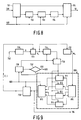
- FIG. 1 which comprises on the one hand a source coder 1 and, between this and a transmission channel 3, a channel coder 2.
- FIG. 2 which comprises on the one hand a source coder 1 and, between this and a transmission channel 3, a channel coder 2.
- FIG. 2 Symmetrically, there is at the output of channel 3 a channel decoder 4 then a source decoder 5.
- FIGS. 2 to 5 an example of a coding system according to the invention, then all that relates to the decoding part located downstream of the channel, that is to say the assembly constituted by the channel decoder and the source decoder, with reference to FIGS. 6 to 9.
- the coding system shown in FIG. 2 first comprises a variable length coding chain 10.
- This chain 10 constitutes the source encoder and essentially comprises, conventionally, an orthogonal transformation and quantization circuit, a variable length coding circuit, and a rate regulation circuit including a buffer memory.
- the coding system then comprises a channel coder 20, itself comprising in series a coding subset with selective protection and a coding subset without selective protection.
- the coding subset with selective protection comprises, more particularly, a stage 100 for coding the cumulative lengths of the code words of a block (the description will be made more concise by speaking of block lengths) originating from the coding chain 10, a stage 200 for selective protection of the information blocks from the coding chain 10, and a stage 300 for multiplexing the signals from said stages 100 and 200 for length coding and selective protection.
- blocks of information is meant subsets of signals of the same dimensions, resulting from a subdivision of the batches of information (for example television images) initially considered.
- These blocks of information after said orthogonal transformation, can, by operations of comparison with thresholds, be classified according to their more or less great activity (linked to the contours, to the contrasts, to the more or less great uniformity of the blocks), and a signal expressing this classification is then emitted by the orthogonal transformation and quantization circuit, and transmitted.
- the flow regulation circuit includes a feedback loop carrying a normalization signal which must also be transmitted.
- the block length coding stage 100 shown in FIG. 3 comprises means (101, 103) for determining the length of each block after variable length coding, means (102, 104) for counting the number of blocks, of which the length is determined, and length coding means. More precisely, this stage 100 firstly comprises a circuit 101 for counting the bits corresponding to a block and a circuit for counting blocks 102. An EOB signal at the end of the block is supplied by the orthogonal transformation circuit and quantization of the chain 10 to the block counting circuit 102, the content of which increases by one with each reception of an EOB signal.
- the block length determined by the circuit 101 is stored in a memory 103, and the counting circuit 101, reset to zero by command of the signal EOB (RS1 connection), is available for a new block length count. Writing to memory 103 (connection WR) is controlled by the signal EOB.
- a decision circuit 104 determines, by comparison with a prerecorded number, from which number of blocks - and therefore of determined lengths - the memory 103 can be read.
- This circuit 104 which is a comparator, is placed at the output of the block counting circuit 102 and delivers (connection RD) a command to read the memory 103 when the content of the circuit 102 (the number of blocks including the lengths have been determined) is equal to the pre-recorded number.
- This read command signal is also sent back to circuit 102 to reset it (RS2 connection).
- the pre-recorded number is for example equal to 4, and the reading of the memory 103 therefore occurs when four lengths have been determined and successively stored.
- This circuit 105 is a systematic linear binary coder, known as a "block" coder, chosen for its ability to correct y errors for x information received: the number x of bits received supplied by the memory 103 to the coding circuit 105 being, as we have seen, at most equal to 40, the maximum number of errors which it is desired to correct for such a number of pieces of information received is equal to 2, and the binary code then chosen is denoted C (52, 40), 40 representing the maximum number of bits received and the remaining 12 bits being parity bits.
- the output of the coding circuit 105 constitutes that of the stage 100 for coding the block lengths.
- the stage 200 for selective protection of the information blocks firstly comprises a memory 201, constituting a circuit for classifying bits according to the sensitivity of the latter to errors caused by the transmission channel. For code words resulting from variable length coding, this sensitivity is determined from prior statistical analyzes, the results of which are grouped in a table associated with the memory 201.
- the bits delivered by the coding chain 10 to variable length are stored in memory 201 and then re-read according to a sequence of addresses contained in the table, with a view to reordering these bits (generally in decreasing sensitivity order), which are then supplied to a circuit selective coding according to said classification, such as an encoder 202 called Blokh-Zyablov, chosen for its ability to allow several levels of coding according to the classification of bits performed.
- a circuit selective coding according to said classification such as an encoder 202 called Blokh-Zyablov, chosen for its ability to allow several levels of coding according to the classification of bits performed.
- this coder 202 is capable of coding at most K bits. If the length L of an information block is less than this coding capacity K, the unused (KL) bits give rise to zeroing in the information chain of length K processed by the Blokh-Zyablov coder 202. If on the contrary the length L is greater than the capacity K, only K bits are coded. The (LK) remaining bits are not coded and are multiplexed with the code words delivered by the Blokh-Zyablov coder, in the multiplexing stage 300.
- a matrix memory 215 for storing the coded output signals of these circuits, then a circuit 216 for matrix multiplication of the content of the memory 215 by the transposed matrix G t of the following matrix G:
- the matrix memory 215 comprises 4 lines, as many as levels of selective protection, and 127 columns. This format is also that of the matrix, denoted C, of the result of said matrix multiplication.
- the EOB end of block signals already mentioned provide the command to write and then read from the memory 215.
- Delay circuits 217 and 218 are interposed in the write and read command connections, respectively WR and RD, of the memory 215 to take account of the duration of the selective coding operations and to synchronize these two commands with respect to the signals to be stored then to be read.
- circuit 216 which constitutes that of encoder 202, is supplied to a shortening circuit 203, making it possible to suppress, possibly, that is to say if they exist, the (KL) bits set to zero, and the output of this circuit 203, which constitutes that of stage 200, is then sent to the multiplexing stage 300.
- the stage 300 ensures, as we have seen, not only the multiplexing of the signals coming from the length coding and selective protection stages, but also that of the excess (LK) bits which could not be coded by the coder 202.
- the multiplexing is carried out, in one or the other case, by a multiplexer 301, and the latter is followed by a buffer memory 302 provided for regulating the output signal rate of the coding sub-assembly with selective protection.
- the variable length coding chain 10 comprises a flow regulation circuit, it is possible to group these flow regulation means and said chain flow regulation circuit 10 into a single regulation sub-assembly. of debt.
- the coding subset without selective protection, referenced 400 and then provided, is generally different depending on whether or not the transmission channel has a memory.
- this coding subset is preferably a Reed-Solomon type coder, with the possible presence of an interleaver per symbol, in the transmission chain, to carry out the adaptation between the length of the error packets and the number of bits constituting the symbols of the Reed-Solomon code.
- the coding subset without selective protection is rather a binary BCH type coder, better suited to the correction of errors whose positions are completely random.
- These Reed-Solomon and BCH codes are for example described in the work "Theory and practice of error control codes", R. Blahut, Addison-Wesley Publishing Company, May 1984.
- This decoding system of FIG. 6 comprises a transmission channel decoder 40 followed by a source decoder 50.
- the channel decoder 40 itself comprises, in series, a non-selective protection decoding sub-assembly, referenced 400 , and a decoding subset with selective protection.
- the decoding sub-assembly with selective protection comprises here, more particularly, a demultiplexing stage 500 for routing the coded digital signals received by the decoding system, a length decoding stage 600, for decoding those of these coded signals received which correspond to the lengths determined in stage 100 of the channel coder 20, and a stage 700 for decoding the other coded signals received.
- the decoding sub-assembly without selective protection receives the input signals of the system, that is to say signals whose multiplexing had been carried out by stage 300 of the channel coder 20, namely: on the one hand the digital signals constituting, after coding in stage 100, the code words corresponding to the lengths of the variable parts of the blocks, on the other hand the digital signals which constitute the code words resulting from the selective protection of the blocks and coming from the stage 200.
- This decoding subset without selective protection comprises, as previously for coding, different circuits according to the type of transmission channel and can be, for example a Reed-Solomon type decoder or a binary BCH type decoder.
- the demultiplexing stage 500 comprises on the one hand means for modifying the bit rate of the signals received, here consisting of a buffer memory 501 which receives the output signals from the decoding sub-assembly without selective protection, and on the other hand signal separation means, consisting here of a demultiplexer 502 providing routing of the output signals from this memory either to the decoding stage 600 or to the decoding stage 700.
- signals received by the stage 500 are signals corresponding, after transmission and passing through the sub-assembly 400, respectively to the coded output signals of the length coding stage 100 and to the coded output signals of the selective protection stage 200.
- the length decoding stage 600 comprises means for decoding the coded signals corresponding to lengths and means for timing said decoding. More precisely, it comprises here first of all, in the embodiment described, a circuit 601 for decoding lengths ensuring the reverse operations of the coding circuit 105, that is to say, in this case, the decoding of code words corresponding to the lengths of four blocks.
- the signals thus decoded are stored in a memory 602, the reading of which takes place at each end of decoding of the decoding stage 700, on command of an end EOD signal. block decoding provided by said stage 700.
- This signal EOD is also supplied to a block counting circuit 603 which commands, after a decoding of four block lengths, the reinitialization of the process for the decoding relating to the following four blocks.
- a comparator 604 here ensures that the counting of the number of blocks stops, and it is the output of this comparator which constitutes the reset control signal, sent to the demultiplexing stage 500, as well as to the counting circuit of blocks 603 for resetting to zero (RESET), and to memory 602 as a write command (WR).
- This stage 700 firstly comprises demultiplexing means consisting here of a demultiplexing circuit 701. Indeed, it is known that, when the length L of an information block, before transmission, is greater than the capacity K of the selective protection stage 200, the remaining (LK) bits, not coded by this stage, are multiplexed with the code words resulting from the coding of the first K bits and delivered by said stage. The reverse demultiplexing operation must then be provided, in this situation, and this is the role of the circuit 701. When on the contrary the length L is not greater than K, the circuit 701 has no demultiplexing to operate and lets through all of the code words delivered by stage 200 and having then passed through the subset 400 and stage 500.
- the demultiplexing circuit 701 is followed by reverse shortening means consisting here of a so-called filling circuit 702 intended to perform a reverse processing of the so-called shortening operation carried out at the output from the Blokh-Zyablov 202 encoder (after the zeroing of (KL) unused bits, when they exist in the information chain of length K processed by this coder 202).
- the function of the circuit 702 is to complete the number of bits missing from the code word received, after the coding carried out in the Blokh-Zyablov coder 202. This lack results, it may be recalled, from the shortening process carried out on transmission when the length L of an information block is less than the capacity K of the selective protection stage.
- the circuit 702 If the number of bits of a block is less than the maximum number of bits of the code word of the encoder 202 (for example 508 bits, in the example described, for this maximum number), the number of zeros necessary to have is added. a full code word. Otherwise, the circuit 702 is transparent, it performs no processing.
- This circuit 702 is followed by selective decoding means which, in the example described, consist of a selective protection decoder such as a so-called Blokh-Zyablov decoder 703.
- This decoder 703 performs the reverse processing of the coding operations performed on transmission by the selective coding circuit.
- the decoder 703, shown in FIG. 9 and described in detail below, is followed by reclassification means consisting here of a circuit 704 for reordering in reverse order to that operated by the bit classification memory 201.
- These reclassification means are themselves followed by storage means such as a memory 705.
- the output of this memory 705 constitutes the output of the decoding stage 700, sent to the source decoder 50.
- the output signal from the memory 602, which is, as we have seen, the length of each block, is supplied, in the decoding stage 700, to the demultiplexing circuit 701, to the filling circuit 702, to the decoder 703, and to the memory 705.
- the Blokh-Zyablov decoder 703 is based on the following operating principle.
- the process thus described is implemented in the following circuits of the Blokh-Zyablov decoder 703 as shown in FIG. 9 and which here comprises four levels of selective protection.
- the output signals of the filling circuit 702, which constitute the input signals of the decoder 703, are stored in a matrix memory 730, therefore containing the expression called R above.
- This matrix memory 730 is followed by a circuit 731 for calculating R i , then by a circuit 732 for matrix multiplication to obtain the matrix expression M i , then sent to the decoding device proper of the decoder 703.
- This decoding device comprises, in a comparable manner with the coding device (210, 211, 212, 213, 214, 215) shown in FIG. 5, firstly a demultiplexing circuit 810, then, in parallel, four selective decoding circuits 811 to 814 each receiving the bits which are assigned to it by the circuit 810. At the output of the four decoding circuits 811 to 814 is then provided a matrix memory 815 for storing the decoded output signals of these circuits. The output of this memory 815 is supplied on the one hand to a circuit 733 of code word reconstruction intended for updating the expression C (k1, ..., k i-1 , 0, ..., 0) denoted by abbreviation C (.) in FIG.
- the output of the memory 815 is also sent, as an output of the Blokh-Zyablov decoder 703, to the reclassification means. , here the reverse order circuit 704.
- This circuit 734 comprises, for carrying out (n-1) error detection cycles, means of comparison between on the one hand the columns of the matrix expression R i and on the other hand, for the (n-1) levels of selective protection other than the first, the sets E2, E3, ..., E n of the words formed respectively by combination of the (n-1) last lines of the matrix G, by combination of (n -2) last lines of G, etc ..., by combination of the last two lines of G, and formed, for the n-th level of selective protection, from the last line of G.
- its address here from 1 to 127) is stored in a 735 m circuit morisation said column addresses.
- a counter 736 for the number of levels of selective protection as well as a comparator 737 ensuring the counting of the number of levels and the emission of an end EOD signal decoding.
Landscapes
- Engineering & Computer Science (AREA)
- Multimedia (AREA)
- Signal Processing (AREA)
- Compression, Expansion, Code Conversion, And Decoders (AREA)
- Error Detection And Correction (AREA)
- Detection And Prevention Of Errors In Transmission (AREA)
Claims (5)
- System zur Kodierung von digitalen Signalen in Informationsblöcken mit einem Quellenkodierer und einem nachfolgenden Übertragungskanalkodierer, dadurch gekennzeichnet, daß wenn der Quellenkodierer ein Kodierungskreis veränderlicher Länge ist, der Kanalkodierer zum selektiven Schützen der Informationen, die für Übertragungsfehler am empfindlichsten sind, eine Reihenschaltung aufweist, bestehend aus einem Hilfskodierer mit selektivem Schutz vom Typ Blokh-Zyablov mit einem nachfolgenden Kodierer ohne solchen selektiven Schutz, wobei der genannte Hilfskodierer vom Typ Blokh-Zyablov die nachfolgenden Elemente aufweist:(A) eine Kodierungsanordnung (100) zur Kodierung der Länge der Blöcke, wobei längs eines Blocks eine akkumulierte Länge von Kodeworten bestimmt wird, die von dem genannten Quellenkodierer geliefert werden und wobei die Kodierung der auf diese Weise bestimmten Blocklängen gewährleistet wird;(B) eine Schaltungsanordnung (200) zum selektiven Schützen der genannten Blöcke durch Kodierung vom Typ Blokh-Zyablov, wobei diese Schaltungsanordnung an sich die nachfolgenden Elemente aufweist:(a) eine Bitklassifikationsschaltung zum Klassifizieren in mehrere Klassen, je nach der Empfindlichkeit für Übertragungsfehler;(b) selektive Kodierungsmittel (102) je nach der genannten Klassifizierung, wobei diese Mittel an sich wieder aus einer Demultiplexerschaltung (210) und nachfolgenden, parallel dazu liegenden selektiven Kodierungsschaltungen (211, 212, 213, 214) bestehen, mit ebensovielen Kodierungspegeln, wie es auf diese Weise bestimmte Klassen gibt, und wobei sich am Ausgang der Kodierungsschaltungen ein Matrixspeicher (215) vorgesehen ist zum Speichern der auf diese Weise kodierten Signale;(c) am Ausgang der genannten selektiven Kodierungsmittel eine Matrix-Multiplizierschaltung (216) für auf diese Weise durch die transponierte Matrix Gt der nachfolgenden Matrix G gebildete kodierte Signale:
 (d) eine selektive Verkürzungsschaltung (203) für das Ausgangssignal der genannten Matrixmultiplizierschaltung, wenn die Kodierungskapazität der genannten Hilfskodierschaltung mit selektivem Schutz größer ist als die Länge der Menge zu kodierender Signale;(C) eine Multiplexerschaltung (300) mit Multiplexierungsmitteln für die Ausgangssignale der Längenkodierungsschaltungen (100, 200) mit selektivem Schutz.
 - Kodierungssystem nach Anspruch 1, dadurch gekennzeichnet, daß die Blocklängenkodierungsanordnung (100) die nachfolgenden Elemente aufweist:(A) Mittel zum Bestimmen der Länge jedes Blocks nach der Kodierung mit veränderlicher Länge, wobei diese Mittel an sind die nachfolgenden Elemente aufweisen:(a) eine Bitzählerschaltung (101) zum für jeden Block Zählen der Anzahl Bits der kodierten Signale mit veränderlicher Länge, die von dem Quellenkodierer geliefert werden zusammen mit jedem Block;(b) einen Speicher (103) zum Speichern des Ausgangssignals der genannten Bitzählerschaltung;(B) Mittel zum Zählen der Anzahl Blöcke, deren Länge bestimmt worden ist, wobei diese Mittel die nachfolgenden Elemente aufweisen:(c) eine Schaltungsanordnung (102) zum Zählen der Blöcke ausgehend von Signalen, die das Ende eines Blocks angeben und ebenfalls von dem genannten Quellenkodierer geliefert werden;(d) eine Entscheidungsschaltung (104) zur Steuerung des Auslesens des Speichers ausgehend von der Anzahl vorgespeicherter Blöcke; (C) Längenkodierungsmittel, welche die nachfolgenden Elemente aufweisen:(e) eine Kodierungsschaltung (105) zum Liefern der Worte für die Längenkodierung der genannten Blöcke.
- Kodierungssystem nach einem der Ansprüche 1 und 2, dadurch gekennzeichnet, daß die Multiplexierstufe ebenfalls Mittel (302) aufweist zur Regelung der Menge an Ausgangssignalen der genannten Multiplexierungsmittel, und daß, wenn die Länge L des betreffenden Blocks die Kodierungskapazität K der genannten selektiven Schutzstufe übersteigt, die genannten Multiplexierungsmittel ebenfalls zur Gewährleistung der Multiplexierung der nicht-kodierten (L-K) Bits vorgesehen sind.
- Kodierungssystem nach einem der Ansprüche 1 bis 3, dadurch gekennzeichnet, daß die Bitsklassifizierungsschaltung einen Speicher (201) aufweist, der dazu vorgesehen ist, in einer ersten Speicherzone die kodierten Signale mit veränderlicher Länge von dem Quellenkodierer zu empfangen und in einer zweiten Speicherzone wegen der Adressierung der ersten Speicherzone zum Liefern der genannten kodierten Signale in einer je nach der genannten Adressierung geänderten Ordnung, den Rang der genannten kodierten Signale.
- Dekodierungssystem zum Dekodieren digitaler Signale, die vorher einer Kodierung in einer Kodierungskette veränderlicher Länge ausgesetzt worden sind, mit einem nachfolgenden Kanalkodierer, der an sich wieder eine Kodierungsanordnung vom Typ Blokh-Zyablov mit selektivem Informationsschutz enthält, mit einem nachfolgenden Kodierer ohne solchen selektiven Schutz, wobei das Dekodierungssystem einen Übertragungskanaldekodierer (40) aufweist mit einem nachfolgenden Quellendekodierer (50), wie eine Dekodierungskette veränderlicher Länge, dadurch gekennzeichnet, daß der Kanaldekodierer in einer Reihenschaltung eine Hilfsdekodierschaltung (400) aufweist mit nicht selektivem Schutz, mit einer nachfolgenden Hilfsdekodierschaltung mit selektivem Schutz, die an sich wieder die nachfolgenden Elemente aufweist:(A) eine Längendekodierungsstufe (600) um es zu ermöglichen, daß während jedes Dekodierungsvorgangs diejenigen empfangenen Signale dekodiert werden, welche den Längen der genannten Blöcke entsprechen;(B) eine Dekodierungsstufe (700) für die anderen empfangenen kodierten Signale;(C) hinter den genannten Dekodierungsstufen in Parallelschaltung eine Demultiplexerschaltung (500), insbesondere zum Schalten der empfangenen kodierten digitalen Signale, entweder zu der genannten Längendekodierstufe oder zu der genannten Stufe zum Dekodieren der anderen kodierten Signale;wobei diese Dekodierstufe (700) zum Dekodieren der anderen empfangenen kodierten Signale an sich die nachfolgenden Elemente aufweist:(1) Demultiplexierungsmittel (701) zum Demultiplexen einerseits der genannten anderen kodierten Signale, und andererseits der etwaigen nicht-kodierten Signale (L-K) von der genannten Kodierung mit selektivem Schutz, wenn die Länge L eines Blocks die Kodierungskapazität K übersteigt;(2) selektive Dekodierungsmittel, die an sich einen Blokh-Zyablov-Dekodierer (703) mit n parallele selektive Dekodierungsschaltungen aufweisen, die an sich aus den nachfolgenden Elementen bestehen:(a) einem Matrixspeicher (730) zum Speichern von Ausgangssignalen der genannten Füllschaltung;(b) einer Rechenschaltung (731) zum Berechnen des Matrixausdrucks Ri = R - C (k₁, k₂, ...ki-1, 0, ... 0), wobei R der Inhalt des genannten Matrixspeichers ist und C (k₁, k₂, ...ki-1, 0, ... 0) das Kodewort, das erhalten wird, wenn alle k₁, die bisher noch nicht dekodiert wurden, als gleich Null betrachtet werden;(c) einer Matrixmultiplikationsschaltung (732) zur Bestimmung des Matrixausdrucks Mi = (Gα)⁻¹.Ri, wobei (Gα)⁻¹ die Inverse der transponierten Matrix der nachfolgenden Matrix G ist:
 (d) einer Dekodieranordnung (800), die an sich eine Demultiplexierschaltung (810) aufweist und in Parallelschaltung n selektive Dekodierschaltungen (811, 812, 813, 814), denen in Reihenschaltung aus einem Matrixspeicher (815) für dekodierte Signale an den Ausgängen der genannten Dekodierschaltungen und einer Rekonstruktionsschaltung (733) für Kodeworte folgt, wobei diese Schaltungsanordnung zur Aktualisierung des Ausdrucks C (k₁, k₂, ...ki-1, 0, ... 0) vorgesehen ist, der der genannten Schaltungsanordnung zur berechnung des Matrixausdrucks R₁ zugeführt wird; und(e) einer Übertragungsfehlerdetektionsschaltung (734) zum Korrigieren der von der genannten Dekodierschaltung durchgeführten Dekodierung, wobei diese Übertragungsfehlerdetektionsschaltung vorzugsweise eine derartige Struktur hat, daß sie zum Verwirklichen der (n-1)-Zyklen von Detektionsfehlern Mittel aufweist zum Vergleichen der Spalten des Matrixausdrucks Ri einerseits und für die (n-1) Pegel des selektiven Schutzes anders als den ersten Pegel, die Gebilde E₂, E₃, ..., En der Worte andererseits, wobei diese Worte durch Kombination der (n-1) letzten Zeilen der Matrix G gebildet werden, durch Kombination der (n-2) letzten Zeilen von G, usw......, und durch Kombination der letzten zwei Zeilen von G, bzw. die aus der letzten Zeile von G für den n. selektiven Schutzpegel gebildet werden;(3) zwischen den genannten Demultiplexermitteln und den selektiven Dekodierungsmitteln inverse Kürzungsmittel (702) zum Einstellen des Formats der zu dekodierenden Signale auf die Kapazität der genannten selektiven Dekodierungsmittel , wenn die Länge L eines Blocks kleiner ist als die genannte Kodierungskapazität K;(4) Reklassierungsmittel (704) zum Reklassieren der dekodierten Signale nach ihrer Empfindlichkeit für Übertragungsfehler;(5) Speichermittel (705) für auf diese Weise reklassierte Signale.
Applications Claiming Priority (6)
| Application Number | Priority Date | Filing Date | Title |
|---|---|---|---|
| FR8917452 | 1989-12-29 | ||
| FR8917452A FR2656754A1 (fr) | 1989-12-29 | 1989-12-29 | Systeme de codage de signaux numeriques destines a etre transmis et/ou stockes. |
| FR9001891A FR2658683A1 (fr) | 1990-02-16 | 1990-02-16 | Systeme de codage a longueur variable de signaux numeriques. |
| FR9001891 | 1990-02-16 | ||
| FR9003406 | 1990-03-16 | ||
| FR9003406A FR2659814A1 (fr) | 1990-03-16 | 1990-03-16 | Systeme de decodage de signaux numeriques ayant subi un codage a longueur variable. |
Publications (3)
| Publication Number | Publication Date |
|---|---|
| EP0436251A2 EP0436251A2 (de) | 1991-07-10 |
| EP0436251A3 EP0436251A3 (en) | 1992-01-08 |
| EP0436251B1 true EP0436251B1 (de) | 1995-09-27 |
Family
ID=27252097
Family Applications (1)
| Application Number | Title | Priority Date | Filing Date |
|---|---|---|---|
| EP90203408A Expired - Lifetime EP0436251B1 (de) | 1989-12-29 | 1990-12-18 | System zur Kodierung/Dekodierung von digitalen Signalen zur Übertragung und/oder Speicherung |
Country Status (4)
| Country | Link |
|---|---|
| US (1) | US5218622A (de) |
| EP (1) | EP0436251B1 (de) |
| JP (1) | JPH04219026A (de) |
| DE (1) | DE69022705T2 (de) |
Families Citing this family (33)
| Publication number | Priority date | Publication date | Assignee | Title |
|---|---|---|---|---|
| US5600672A (en) | 1991-03-27 | 1997-02-04 | Matsushita Electric Industrial Co., Ltd. | Communication system |
| USRE42643E1 (en) | 1991-03-27 | 2011-08-23 | Panasonic Corporation | Communication system |
| USRE40241E1 (en) | 1991-03-27 | 2008-04-15 | Matsushita Electric Industrial Co., Ltd. | Communication system |
| USRE39890E1 (en) | 1991-03-27 | 2007-10-23 | Matsushita Electric Industrial Co., Ltd. | Communication system |
| SG65702A1 (en) * | 1991-04-10 | 1999-06-22 | Mitsubishi Electric Corp | Encorder and decorder |
| JPH04358486A (ja) * | 1991-06-04 | 1992-12-11 | Toshiba Corp | 高能率符号化信号処理装置 |
| JPH05115010A (ja) * | 1991-10-22 | 1993-05-07 | Canon Inc | 画像復号化装置 |
| JPH05199122A (ja) * | 1992-01-20 | 1993-08-06 | Canon Inc | 復号回路 |
| US6724976B2 (en) * | 1992-03-26 | 2004-04-20 | Matsushita Electric Industrial Co., Ltd. | Communication system |
| USRE38513E1 (en) | 1992-03-26 | 2004-05-11 | Matsushita Electric Industrial Co., Ltd. | Communication system |
| US7158577B1 (en) | 1992-03-26 | 2007-01-02 | Matsushita Electric Industrial Co., Ltd. | Communication system |
| US5802241A (en) | 1992-03-26 | 1998-09-01 | Matsushita Electric Industrial Co., Ltd. | Communication system |
| CN1032099C (zh) * | 1992-03-26 | 1996-06-19 | 松下电器产业株式会社 | 通信系统 |
| US6728467B2 (en) * | 1992-03-26 | 2004-04-27 | Matsushita Electric Industrial Co., Ltd. | Communication system |
| US7894541B2 (en) * | 1992-03-26 | 2011-02-22 | Panasonic Corporation | Communication system |
| JPH05344162A (ja) * | 1992-06-09 | 1993-12-24 | Canon Inc | データ伝送装置 |
| JPH06125533A (ja) * | 1992-10-13 | 1994-05-06 | Sony Corp | エラー訂正コード付加装置及びエラー訂正装置 |
| US5430743A (en) * | 1993-06-29 | 1995-07-04 | Motorola, Inc. | Method and apparatus for recovering data in a radio communication system |
| ES2198452T3 (es) * | 1995-06-12 | 2004-02-01 | Siemens Aktiengesellschaft | Procedimiento e instalacion de codificacion para la transmision segura de datos por medio de codificacion de componentes multiples. |
| US6571361B1 (en) * | 1995-09-29 | 2003-05-27 | Kabushiki Kaisha Toshiba | Encoder and decoder |
| US6173431B1 (en) * | 1998-07-01 | 2001-01-09 | Motorola, Inc. | Method and apparatus for transmitting and receiving information packets using multi-layer error detection |
| DE19857677B4 (de) * | 1998-12-14 | 2008-04-24 | Siemens Ag | Verfahren und Anordnung zur Kodierung von Symbolen für eine Übertragung über eine Funkschnittstelle eines Funk-Kommunikationssystems |
| JP2001024515A (ja) * | 1999-07-07 | 2001-01-26 | Sony Corp | 信号処理方法及び装置 |
| DE19959178A1 (de) * | 1999-12-08 | 2001-06-13 | Siemens Ag | Verfahren und Anordnung zur Decodierung von Informationen |
| WO2002014981A2 (en) * | 2000-08-14 | 2002-02-21 | Audi Performance & Racing | Enhanced module chipping system |
| DE10051820A1 (de) * | 2000-10-19 | 2002-05-08 | Deutsche Telekom Ag | Verbesserung der Übertragungsqualität im Mobilfunk |
| JP3415126B2 (ja) * | 2001-09-04 | 2003-06-09 | 三菱電機株式会社 | 可変長符号多重化装置、可変長符号分離装置、可変長符号多重化方法及び可変長符号分離方法 |
| DE10252836A1 (de) * | 2002-11-13 | 2004-05-27 | Patent-Treuhand-Gesellschaft für elektrische Glühlampen mbH | Vorrichtung zum Betreiben von Entlaudungslampen |
| US7685500B2 (en) * | 2003-11-25 | 2010-03-23 | Intel Corporation | Forward error correction coding in communication networks |
| DE102006036460B4 (de) * | 2006-08-04 | 2015-04-09 | Aesculap Ag | Siebkorb |
| JP5049942B2 (ja) * | 2008-10-28 | 2012-10-17 | キヤノン株式会社 | 復号装置、復号方法、及びプログラム |
| US10484019B2 (en) * | 2017-10-30 | 2019-11-19 | Western Digital Technologies, Inc. | Adaptive encoder/decoder |
| US10691537B2 (en) * | 2018-10-12 | 2020-06-23 | Western Digital Technologies, Inc. | Storing deep neural network weights in non-volatile storage systems using vertical error correction codes |
Family Cites Families (7)
| Publication number | Priority date | Publication date | Assignee | Title |
|---|---|---|---|---|
| US3971888A (en) * | 1975-04-02 | 1976-07-27 | Bell Telephone Laboratories, Incorporated | Synchronization system for variable length encoded signals |
| DE3411962A1 (de) * | 1983-03-31 | 1984-10-31 | Sansui Electric Co., Ltd., Tokio/Tokyo | Datenuebertragungseinrichtung |
| CA1261069A (en) * | 1986-12-08 | 1989-09-26 | Mohamed S. Sabri | Two-channel coding of digital signals |
| FR2617657A1 (fr) * | 1987-07-03 | 1989-01-06 | Trt Telecom Radio Electr | Systeme de transmission de series d'echantillons numeriques codes par des mots binaires a longueurs variables |
| US4939583A (en) * | 1987-09-07 | 1990-07-03 | Hitachi, Ltd. | Entropy-coding system |
| FR2625638B1 (fr) * | 1987-12-30 | 1994-06-17 | Thomson Grand Public | Procede de synchronisation pour la transmission, sur un canal asynchrone, d'une suite d'images codees au moyen d'un code a longueur variable, et dispositif pour la mise en oeuvre de ce procede |
| JPH0810935B2 (ja) * | 1988-12-09 | 1996-01-31 | 富士写真フイルム株式会社 | 画像信号圧縮符号化装置および伸長再生装置 |
-
1990
- 1990-12-18 DE DE69022705T patent/DE69022705T2/de not_active Expired - Fee Related
- 1990-12-18 EP EP90203408A patent/EP0436251B1/de not_active Expired - Lifetime
- 1990-12-20 US US07/630,700 patent/US5218622A/en not_active Expired - Fee Related
- 1990-12-28 JP JP90418090A patent/JPH04219026A/ja active Pending
Also Published As
| Publication number | Publication date |
|---|---|
| DE69022705D1 (de) | 1995-11-02 |
| DE69022705T2 (de) | 1996-05-23 |
| US5218622A (en) | 1993-06-08 |
| EP0436251A2 (de) | 1991-07-10 |
| JPH04219026A (ja) | 1992-08-10 |
| EP0436251A3 (en) | 1992-01-08 |
Similar Documents
| Publication | Publication Date | Title |
|---|---|---|
| EP0436251B1 (de) | System zur Kodierung/Dekodierung von digitalen Signalen zur Übertragung und/oder Speicherung | |
| EP0108655B1 (de) | System zur Erkennung und Korrektur von Übertragungsfehlern in einer binären Nachricht mit einem Fehlererkennungs- und Korrekturcode des verzahnten zyklischen Reed-Solomon-Typs | |
| EP0323363B1 (de) | Verfahren zur Synchronisierung für die Übertragung über einen asynchronen Kanal einer Folge von kodierten Bildern, die mittels eines Kodes mit variabler Länge kodiert sind und Einrichtung zur Durchführung dieses Verfahrens | |
| EP0442548B1 (de) | Vorrichtungen zur variablen Längen-Kodierung und Dekodierung von digitalen Daten | |
| FR2815199A1 (fr) | Procedes de turbocodage circulaire de grande distance minimale, et systemes pour leur mise en oeuvre | |
| FR2785743A1 (fr) | Dispositif et procede d'adaptation des turbocodeurs et des decodeurs associes a des sequences de longueur variable | |
| EP0808538B1 (de) | Verfahren, modul und vorrichtung zum empfang digitaler signale mit iterativer arbeitsweise | |
| EP1332557B1 (de) | Modul, vorrichtung und verfahren zum hochbitratigen dekodieren eines verketteten codes | |
| FR2747255A1 (fr) | Procede et dispositif de codage convolutif de blocs de donnees, et procede et dispositif de decodage correspondants | |
| EP0448491A1 (de) | Verfahren zur Kodierung und Übertragung von digitalen Bildern einer Bildsequenz mit mindestens zwei Qualitätsniveaus und zugehörige GerÀ¤te | |
| FR2471094A1 (fr) | Circuit interpolateur augmentant le debit de mots d'un signal numerique du type utilise dans les systemes telephoniques a commutation numerique et joncteur de ligne equipe d'un tel circuit | |
| FR2849514A1 (fr) | Code de geometrie algebrique adapte aux erreurs en rafale | |
| WO1999057816A1 (fr) | Decodage iteratif de codes produits | |
| FR2486334A1 (fr) | Procede pour numeriser un signal video discret dans le temps avec utilisation d'une transformation d'image | |
| EP0848524A1 (de) | Punktierte, trelliskodierte QAM, mit iterativer Dekodierung | |
| FR2790621A1 (fr) | Dispositif et procede d'entrelacement pour turbocodage et turbodecodage | |
| EP2330745A1 (de) | Dekodierverfahren und Dekodiervorrichtung einer Folge von kodierten Blöcken mit Fehlerkorrekturkode, die untereinander über einen Übertragungskanal verbunden sind | |
| EP0323362B1 (de) | Adaptives Verfahren zur Transformationskodierung und -dekodierung einer Folge von Bildern und Einrichtungen zur Durchführung dieses Verfahrens | |
| EP0204635A1 (de) | Verfahren zur Übertragung von digitaler Information in Wörterblöcken | |
| CA2045882C (fr) | Circuit de decodage de codes convolutionnels pour l'execution de l'etape de stockage et d'exploration inverse des chemins survivants d'un algorithme de viterbi | |
| EP0204612A1 (de) | Verfahren zur Datenübertragung mit Möglichkeit zur Korrektur von Fehlerpaketen und Kodierungs- und Dekodierungsanordnung zur Durchführung dieses Verfahrens | |
| FR2866998A1 (fr) | Decodage et correction d'erreurs pour codes de geometrie algebrique | |
| EP0338899A1 (de) | Verfahren zur Kodierung und Dekodierung von Blockinformationen und Vorrichtung dazu | |
| EP0053064B1 (de) | Digitales Übertragungssystem mit adaptiver Codierung abgetasteter und orthogonal transformierter, analoger Informationen | |
| FR2834146A1 (fr) | Turbo-decodeur compact a haute efficacite |
Legal Events
| Date | Code | Title | Description |
|---|---|---|---|
| PUAI | Public reference made under article 153(3) epc to a published international application that has entered the european phase |
Free format text: ORIGINAL CODE: 0009012 |
|
| AK | Designated contracting states |
Kind code of ref document: A2 Designated state(s): DE FR GB |
|
| PUAL | Search report despatched |
Free format text: ORIGINAL CODE: 0009013 |
|
| AK | Designated contracting states |
Kind code of ref document: A3 Designated state(s): DE FR GB |
|
| 17P | Request for examination filed |
Effective date: 19920707 |
|
| 17Q | First examination report despatched |
Effective date: 19940502 |
|
| GRAA | (expected) grant |
Free format text: ORIGINAL CODE: 0009210 |
|
| AK | Designated contracting states |
Kind code of ref document: B1 Designated state(s): DE FR GB |
|
| REF | Corresponds to: |
Ref document number: 69022705 Country of ref document: DE Date of ref document: 19951102 |
|
| GBT | Gb: translation of ep patent filed (gb section 77(6)(a)/1977) |
Effective date: 19951215 |
|
| REG | Reference to a national code |
Ref country code: FR Ref legal event code: CJ Ref country code: FR Ref legal event code: CD |
|
| PLBE | No opposition filed within time limit |
Free format text: ORIGINAL CODE: 0009261 |
|
| STAA | Information on the status of an ep patent application or granted ep patent |
Free format text: STATUS: NO OPPOSITION FILED WITHIN TIME LIMIT |
|
| 26N | No opposition filed | ||
| PGFP | Annual fee paid to national office [announced via postgrant information from national office to epo] |
Ref country code: GB Payment date: 19971201 Year of fee payment: 8 |
|
| PGFP | Annual fee paid to national office [announced via postgrant information from national office to epo] |
Ref country code: FR Payment date: 19971223 Year of fee payment: 8 |
|
| PGFP | Annual fee paid to national office [announced via postgrant information from national office to epo] |
Ref country code: DE Payment date: 19980223 Year of fee payment: 8 |
|
| PG25 | Lapsed in a contracting state [announced via postgrant information from national office to epo] |
Ref country code: GB Free format text: LAPSE BECAUSE OF NON-PAYMENT OF DUE FEES Effective date: 19981218 |
|
| GBPC | Gb: european patent ceased through non-payment of renewal fee |
Effective date: 19981218 |
|
| PG25 | Lapsed in a contracting state [announced via postgrant information from national office to epo] |
Ref country code: FR Free format text: LAPSE BECAUSE OF NON-PAYMENT OF DUE FEES Effective date: 19990831 |
|
| REG | Reference to a national code |
Ref country code: FR Ref legal event code: ST |
|
| PG25 | Lapsed in a contracting state [announced via postgrant information from national office to epo] |
Ref country code: DE Free format text: LAPSE BECAUSE OF NON-PAYMENT OF DUE FEES Effective date: 19991001 |