EP0436368A2 - Bremsleuchte für Fahrzeuge - Google Patents
Bremsleuchte für Fahrzeuge Download PDFInfo
- Publication number
- EP0436368A2 EP0436368A2 EP90314125A EP90314125A EP0436368A2 EP 0436368 A2 EP0436368 A2 EP 0436368A2 EP 90314125 A EP90314125 A EP 90314125A EP 90314125 A EP90314125 A EP 90314125A EP 0436368 A2 EP0436368 A2 EP 0436368A2
- Authority
- EP
- European Patent Office
- Prior art keywords
- vehicle
- brake
- brake light
- braking
- braking system
- Prior art date
- Legal status (The legal status is an assumption and is not a legal conclusion. Google has not performed a legal analysis and makes no representation as to the accuracy of the status listed.)
- Withdrawn
Links
Images


Classifications
-
- B—PERFORMING OPERATIONS; TRANSPORTING
- B60—VEHICLES IN GENERAL
- B60Q—ARRANGEMENT OF SIGNALLING OR LIGHTING DEVICES, THE MOUNTING OR SUPPORTING THEREOF OR CIRCUITS THEREFOR, FOR VEHICLES IN GENERAL
- B60Q1/00—Arrangement of optical signalling or lighting devices, the mounting or supporting thereof or circuits therefor
- B60Q1/26—Arrangement of optical signalling or lighting devices, the mounting or supporting thereof or circuits therefor the devices being primarily intended to indicate the vehicle, or parts thereof, or to give signals, to other traffic
- B60Q1/44—Arrangement of optical signalling or lighting devices, the mounting or supporting thereof or circuits therefor the devices being primarily intended to indicate the vehicle, or parts thereof, or to give signals, to other traffic for indicating braking action or preparation for braking, e.g. by detection of the foot approaching the brake pedal
- B60Q1/444—Arrangement of optical signalling or lighting devices, the mounting or supporting thereof or circuits therefor the devices being primarily intended to indicate the vehicle, or parts thereof, or to give signals, to other traffic for indicating braking action or preparation for braking, e.g. by detection of the foot approaching the brake pedal with indication of the braking strength or speed changes, e.g. by changing shape or intensity of the indication
Definitions
- This invention relates to road vehicle brake lights.
- the invention is concerned with a road vehicle having a braking system, at least one brake light, and means for operating the brake light in response to operation of the braking system to indicate to road users following the vehicle that the vehicle is being braked.
- Such a system is known, and indeed has been compulsory in many countries for many years.
- a brake light of 21W power, a tail light of 5W and a fog light of 21W to be clustered together fairly closely at the rear of the vehicle, and indeed it is common for the tail and brake lights to be provided by the same bulb.
- the power of the light cluster is 26W, and when the vehicle is braked, the power rises to 47W.
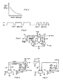
- the present invention provides a solution to the above-mentioned problem by causing the brake lights to flash, preferably with a flashing characteristic (such as the flash "on" period) which varies according to the degree of braking.
- a flashing characteristic such as the flash "on" period
- the flashing of the brake light means that a following road user will be repeatedly warned that the vehicle is being braked.
- the characteristic of the flash with changes in the degree of braking, the following road user will be given an indication of how hard the vehicle is being braked, especially if similar flashing characteristics are generally adopted in any particular country.
- a motor car 10 has a pair of rear light clusters 12, 14, each having a turn indicator 16, combined tail and brake light 18, and a reflector 20. Also, adjacent each cluster 12, 14, there is a rear fog warning light 22.
- the braking system of the car comprises a foot pedal 24 which operates a hydraulic master cylinder 26.
- An arrangement of pipes 28 connects the master cylinder 26 to four slave cylinders 30 which actuate the brake for each wheel of the car.
- the electrical brake light circuit shown in Figure 2 includes a brake switch 32 operated by the foot pedal 24 and connected on one side to the car's electrical supply.
- the circuit also includes the brake filaments of the tail/brake lights 18 which are grounded on one side. Rather than the other side of each brake light filament being connected directly to the brake switch 32, they are connected via a flasher unit 34.
- the arrangement also includes a pressure transducer 36 which is connected to the brake pipe 28 and supplies an electrical signal on the line 38 to the flasher unit 34.
- flasher unit comprises an astable multivibrator circuit having a constant time period in one state defined by resistor R1 and capacitor C1 and a variable time period in the opposite state defined by the capacitor C2 and the resistance between line 38 and the supply voltage, if a transducer 36 is used which provides a variable effective resistance between the line 38 and the supply voltage line, or by an optional resistor R2 (shown in dotted line) and the voltage on line 38 if a transducer 36 is used which provides a variable effective voltage on line 38.
- One side of the multivibrator has a simple load resistor R3, and the other side is loaded by the coil RC of a relay 40 with a reverse biased diode D included to clamp coil induced voltages.
- the positive rail 42 of the multivibrator is connected to the brake switch 32 so that the multivibrator is powered up only when the brake pedal 24 is depressed.
- the relay 40 has a switch RS connected between the positive rail 42 and the brake lights 18.
- the circuit may be set up so that the constant "off” period is, for example, in the range of 0.3 to 0.5 seconds and so that the "on” period is variable between, for example, 2 seconds for light braking and the same period as the "off" period for maximum braking, i.e. 0.3 to 0.5 seconds.
- an integrated timer circuit may be used such as type NE555V.
- the pressure transducer may be of the piezo-electric type or other suitable type.
- an electrical potentiometer 44 with on-off switch is coupled via a linkage 46 and crank 48 to the brake pedal 24.
- the on-off switch is connected between the positive supply and a line 50 to the positive rail 42 of the multivibrator, and the potentiometer is connected between the positive supply and the line 38 to the capacitor C2 of the multivibrator.
- an accelerometer 52 is used which supplies a signal on line 38 which varies with the degree of deceleration of the vehicle and therefore varies the "on" flash period in a similar manner to that described above.
- Figure 8 shows a further alternative arrangement, which is especially suitable for a vehicle which has electronic instrumentation.
- a pulse generator 54 detects rotation of a gearbox output shaft 56 of the vehicle and provides a series of pulses on line 58 having a frequency dependent on the speed of rotation.
- the signal on line 58 is processed by a circuit 60 and supplied to an odometer 62 which displays the distance travelled by the vehicle.
- the signal on line 58 is also differentiated by a circuit 64 to produce a signal on line 66 dependent on the speed of the vehicle, and this signal is processed by a circuit 68 and supplied to a speedometer 70.
- the signal on line 66 is also differentiated by a circuit 72 to produce a signal on line 74 which is dependent on the accleration of the vehicle, and this signal is processed by a circuit 76 and supplied to the timer.
- the timer also receives a signal from the brake switch 32, and when the switch is closed, operates the brake lights 18 with a characteristic which varies with the accleration or deceleration of the vehicle. It will be appreciated that a vehicle which has electronic instrumentation will already be fitted with many of the elements of the arrangement of Figure 8, indeed those to the left of the chain-dotted line, and that the only additional elements which are required to incoporate the invention are the differentiator, signal processing and time circuits 72, 76, 34, respectively.
- the vehicle may be fitted with a high-level central brake light (as is commonly fitted to, for example, Volvo (RTM) cars), and in this case the central light may be flashed as described above, whereas the left and right brake lights are lit continuously while the brake is applied.
- a high-level central brake light as is commonly fitted to, for example, Volvo (RTM) cars
- a relay may be included in the supply to the rear fog lights so that when they are on and the brake is applied, the rear fog lights flash in unison with the brake light(s).
Landscapes
- Engineering & Computer Science (AREA)
- Mechanical Engineering (AREA)
- Lighting Device Outwards From Vehicle And Optical Signal (AREA)
Applications Claiming Priority (2)
| Application Number | Priority Date | Filing Date | Title |
|---|---|---|---|
| GB9000021A GB2239701A (en) | 1990-01-02 | 1990-01-02 | Road vehicle brake lights |
| GB9000021 | 1990-01-02 |
Publications (2)
| Publication Number | Publication Date |
|---|---|
| EP0436368A2 true EP0436368A2 (de) | 1991-07-10 |
| EP0436368A3 EP0436368A3 (en) | 1992-03-04 |
Family
ID=10668747
Family Applications (1)
| Application Number | Title | Priority Date | Filing Date |
|---|---|---|---|
| EP19900314125 Withdrawn EP0436368A3 (en) | 1990-01-02 | 1990-12-21 | Road vehicle brake lights |
Country Status (2)
| Country | Link |
|---|---|
| EP (1) | EP0436368A3 (de) |
| GB (1) | GB2239701A (de) |
Cited By (12)
| Publication number | Priority date | Publication date | Assignee | Title |
|---|---|---|---|---|
| WO1993011000A1 (en) * | 1991-11-28 | 1993-06-10 | Bennett, David, Charles | Panic stop brake/hazard flasher |
| GB2269493A (en) * | 1992-08-06 | 1994-02-09 | Peter William Neale | Emergency braking warning system |
| ES2064174A1 (es) * | 1991-04-02 | 1995-01-16 | Moreno Jose Fajardo | Avisador de señalizacion optica dirigido a la seguridad vial. |
| ES2129007A1 (es) * | 1997-10-28 | 1999-05-16 | Garcia Ricardo Garcia | Sistema de señalizacion optico-luminoso producido por el pedal del freno en vehiculos a motor. |
| FR2789953A1 (fr) * | 1999-02-22 | 2000-08-25 | Serge Schlee | Avertisseur lumineux avec calculateur de pression de freinage |
| FR2797827A1 (fr) * | 1999-08-30 | 2001-03-02 | Bernard Duval | Amelioration de la securite passive des vehicules automobiles grace a differentes combinaisons de l'allumage des feux stop et/ou de detresse |
| FR2818942A1 (fr) * | 2000-12-28 | 2002-07-05 | Denis Francois Rene Michel | Dispositif de visualisation du taux de freinage d'un vehicule |
| WO2008120045A1 (en) * | 2007-03-30 | 2008-10-09 | Blc Paws, Llc | A way of controlling vehicle brake lights and a circuit designed to realize this control |
| ES2334311A1 (es) * | 2008-04-25 | 2010-03-08 | Sergio Garcia Torralba | Sistema electronico de señalizacion de frenado. |
| ES2379930A1 (es) * | 2008-09-12 | 2012-05-07 | Antena Suroeste S.L. | Indicador de intensidad de frenada. |
| US9139131B2 (en) | 2014-01-14 | 2015-09-22 | Blc Paws, Llc | Illuminated vehicle warning system |
| US9855889B1 (en) | 2014-07-17 | 2018-01-02 | B&M, L.L.C. | Brake light system for vehicles |
Families Citing this family (5)
| Publication number | Priority date | Publication date | Assignee | Title |
|---|---|---|---|---|
| DE4305186C2 (de) * | 1993-02-19 | 1996-02-01 | Gerhaher Max | Verfahren zur Reduzierung der Gefahr von Auffahrunfällen im Straßenverkehr durch eine Verzögerungswarnung und Verzögerungswarnanlage |
| US5886628A (en) | 1997-07-29 | 1999-03-23 | Alhassoon; Adel A. | Delayed auto brake light |
| GB2328092A (en) * | 1997-08-02 | 1999-02-10 | Christopher Peter Hall | Vehicle braking intensity indicator |
| GB2332041A (en) * | 1997-12-03 | 1999-06-09 | Noel Edward Harvey | Flashing brake lights for motor vehicle |
| GB2339501A (en) * | 1998-07-10 | 2000-01-26 | Paul Kirkman Sarjeant | Vehicle braking strength indicator |
Family Cites Families (6)
| Publication number | Priority date | Publication date | Assignee | Title |
|---|---|---|---|---|
| US3702459A (en) * | 1971-06-03 | 1972-11-07 | Gen Motors Corp | Vehicle deceleration circuit |
| FR2163878A5 (de) * | 1971-12-03 | 1973-07-27 | Labinal | |
| US3787808A (en) * | 1972-03-02 | 1974-01-22 | K Knopf | Automobile signalling system |
| DE3123277A1 (de) * | 1981-06-12 | 1983-01-05 | Dr. Weusthoff KG, 4000 Düsseldorf | Signalsystem fuer kraftfahrzeuge |
| DE3538886A1 (de) * | 1985-11-02 | 1987-05-07 | Frans Pannekoek | Anordnung an kraftfahrzeugen zur betaetigung der bremsleuchten |
| GB2213658A (en) * | 1987-12-09 | 1989-08-16 | Martin Stephen Richar Broadway | Variable intensity braking light |
-
1990
- 1990-01-02 GB GB9000021A patent/GB2239701A/en not_active Withdrawn
- 1990-12-21 EP EP19900314125 patent/EP0436368A3/en not_active Withdrawn
Cited By (13)
| Publication number | Priority date | Publication date | Assignee | Title |
|---|---|---|---|---|
| ES2064174A1 (es) * | 1991-04-02 | 1995-01-16 | Moreno Jose Fajardo | Avisador de señalizacion optica dirigido a la seguridad vial. |
| WO1993011000A1 (en) * | 1991-11-28 | 1993-06-10 | Bennett, David, Charles | Panic stop brake/hazard flasher |
| GB2269493A (en) * | 1992-08-06 | 1994-02-09 | Peter William Neale | Emergency braking warning system |
| ES2129007A1 (es) * | 1997-10-28 | 1999-05-16 | Garcia Ricardo Garcia | Sistema de señalizacion optico-luminoso producido por el pedal del freno en vehiculos a motor. |
| FR2789953A1 (fr) * | 1999-02-22 | 2000-08-25 | Serge Schlee | Avertisseur lumineux avec calculateur de pression de freinage |
| FR2797827A1 (fr) * | 1999-08-30 | 2001-03-02 | Bernard Duval | Amelioration de la securite passive des vehicules automobiles grace a differentes combinaisons de l'allumage des feux stop et/ou de detresse |
| FR2818942A1 (fr) * | 2000-12-28 | 2002-07-05 | Denis Francois Rene Michel | Dispositif de visualisation du taux de freinage d'un vehicule |
| WO2008120045A1 (en) * | 2007-03-30 | 2008-10-09 | Blc Paws, Llc | A way of controlling vehicle brake lights and a circuit designed to realize this control |
| US8144004B2 (en) | 2007-03-30 | 2012-03-27 | Blc Paws, Llc | Method and apparatus for controlling vehicle brake lights |
| ES2334311A1 (es) * | 2008-04-25 | 2010-03-08 | Sergio Garcia Torralba | Sistema electronico de señalizacion de frenado. |
| ES2379930A1 (es) * | 2008-09-12 | 2012-05-07 | Antena Suroeste S.L. | Indicador de intensidad de frenada. |
| US9139131B2 (en) | 2014-01-14 | 2015-09-22 | Blc Paws, Llc | Illuminated vehicle warning system |
| US9855889B1 (en) | 2014-07-17 | 2018-01-02 | B&M, L.L.C. | Brake light system for vehicles |
Also Published As
| Publication number | Publication date |
|---|---|
| EP0436368A3 (en) | 1992-03-04 |
| GB9000021D0 (en) | 1990-03-07 |
| GB2239701A (en) | 1991-07-10 |
Similar Documents
| Publication | Publication Date | Title |
|---|---|---|
| EP0436368A2 (de) | Bremsleuchte für Fahrzeuge | |
| US5594416A (en) | Deceleration warning system | |
| US6023221A (en) | System to activate automobile hazard warning lights | |
| US5404130A (en) | Sudden-stop brake-light warning system | |
| CA1338563C (en) | System for indicating that a vehicle is slowing down | |
| US20140002259A1 (en) | Automotive brake light with graduated display | |
| US3026498A (en) | Safe trailing distance warning systems for vehicles | |
| US5442333A (en) | Urgent braking device | |
| DE19729784A1 (de) | Steuerung von Signaleinrichtungen an Fahrzeugen mittels Beschleunigungssensoren | |
| JPH01127965A (ja) | 自動車に使用することができる急な減速を検知する自動的な装置 | |
| SU1245256A3 (ru) | Устройство дл регулировани тормозного давлени в автомобил х | |
| EP0053033A1 (de) | Schlupfanzeigesystem für ein Fahrzeug mit vier Treibrädern | |
| US5818332A (en) | Automobile speed indicator | |
| EP1193127B1 (de) | Integrierter bremsanzeiger für fahrzeuge | |
| WO1993011000A1 (en) | Panic stop brake/hazard flasher | |
| US4425560A (en) | Highway hazard warning sign signal | |
| EP0440468A2 (de) | Signalverfahren für Fahrzeuge | |
| GB2300908A (en) | Flashing brake lamps | |
| GB2233843A (en) | Deceleration responsive vehicle brake light system | |
| AU692020B2 (en) | Acceleration warning display unit | |
| KR100240699B1 (ko) | 오일 교환시기 경고시스템 | |
| JPS638507Y2 (de) | ||
| KR0158365B1 (ko) | 자동차의 브레이크등 자동 점멸 장치 | |
| WO1992019467A2 (en) | Sudden-stop brake-light warning system | |
| KR19980060569A (ko) | 차량의 브레이크패드 및 타이어 교체시기 표시방법 |
Legal Events
| Date | Code | Title | Description |
|---|---|---|---|
| PUAI | Public reference made under article 153(3) epc to a published international application that has entered the european phase |
Free format text: ORIGINAL CODE: 0009012 |
|
| AK | Designated contracting states |
Kind code of ref document: A2 Designated state(s): AT BE CH DE DK ES FR GB GR IT LI LU NL SE |
|
| PUAL | Search report despatched |
Free format text: ORIGINAL CODE: 0009013 |
|
| AK | Designated contracting states |
Kind code of ref document: A3 Designated state(s): AT BE CH DE DK ES FR GB GR IT LI LU NL SE |
|
| STAA | Information on the status of an ep patent application or granted ep patent |
Free format text: STATUS: THE APPLICATION IS DEEMED TO BE WITHDRAWN |
|
| 18D | Application deemed to be withdrawn |
Effective date: 19920905 |