EP0436397B1 - Synthétiseur de son - Google Patents
Synthétiseur de son Download PDFInfo
- Publication number
- EP0436397B1 EP0436397B1 EP90314403A EP90314403A EP0436397B1 EP 0436397 B1 EP0436397 B1 EP 0436397B1 EP 90314403 A EP90314403 A EP 90314403A EP 90314403 A EP90314403 A EP 90314403A EP 0436397 B1 EP0436397 B1 EP 0436397B1
- Authority
- EP
- European Patent Office
- Prior art keywords
- sets
- block
- cumulative probability
- stored
- coefficients
- Prior art date
- Legal status (The legal status is an assumption and is not a legal conclusion. Google has not performed a legal analysis and makes no representation as to the accuracy of the status listed.)
- Expired - Lifetime
Links
Images




Classifications
-
- H—ELECTRICITY
- H03—ELECTRONIC CIRCUITRY
- H03M—CODING; DECODING; CODE CONVERSION IN GENERAL
- H03M7/00—Conversion of a code where information is represented by a given sequence or number of digits to a code where the same, similar or subset of information is represented by a different sequence or number of digits
- H03M7/30—Compression; Expansion; Suppression of unnecessary data, e.g. redundancy reduction
- H03M7/3082—Vector coding
-
- G—PHYSICS
- G10—MUSICAL INSTRUMENTS; ACOUSTICS
- G10H—ELECTROPHONIC MUSICAL INSTRUMENTS; INSTRUMENTS IN WHICH THE TONES ARE GENERATED BY ELECTROMECHANICAL MEANS OR ELECTRONIC GENERATORS, OR IN WHICH THE TONES ARE SYNTHESISED FROM A DATA STORE
- G10H7/00—Instruments in which the tones are synthesised from a data store, e.g. computer organs
-
- G—PHYSICS
- G10—MUSICAL INSTRUMENTS; ACOUSTICS
- G10K—SOUND-PRODUCING DEVICES; METHODS OR DEVICES FOR PROTECTING AGAINST, OR FOR DAMPING, NOISE OR OTHER ACOUSTIC WAVES IN GENERAL; ACOUSTICS NOT OTHERWISE PROVIDED FOR
- G10K15/00—Acoustics not otherwise provided for
- G10K15/02—Synthesis of acoustic waves
-
- G—PHYSICS
- G10—MUSICAL INSTRUMENTS; ACOUSTICS
- G10H—ELECTROPHONIC MUSICAL INSTRUMENTS; INSTRUMENTS IN WHICH THE TONES ARE GENERATED BY ELECTROMECHANICAL MEANS OR ELECTRONIC GENERATORS, OR IN WHICH THE TONES ARE SYNTHESISED FROM A DATA STORE
- G10H2250/00—Aspects of algorithms or signal processing methods without intrinsic musical character, yet specifically adapted for or used in electrophonic musical processing
- G10H2250/005—Algorithms for electrophonic musical instruments or musical processing, e.g. for automatic composition or resource allocation
- G10H2250/015—Markov chains, e.g. hidden Markov models [HMM], for musical processing, e.g. musical analysis or musical composition
-
- G—PHYSICS
- G10—MUSICAL INSTRUMENTS; ACOUSTICS
- G10H—ELECTROPHONIC MUSICAL INSTRUMENTS; INSTRUMENTS IN WHICH THE TONES ARE GENERATED BY ELECTROMECHANICAL MEANS OR ELECTRONIC GENERATORS, OR IN WHICH THE TONES ARE SYNTHESISED FROM A DATA STORE
- G10H2250/00—Aspects of algorithms or signal processing methods without intrinsic musical character, yet specifically adapted for or used in electrophonic musical processing
- G10H2250/131—Mathematical functions for musical analysis, processing, synthesis or composition
- G10H2250/211—Random number generators, pseudorandom generators, classes of functions therefor
-
- G—PHYSICS
- G10—MUSICAL INSTRUMENTS; ACOUSTICS
- G10H—ELECTROPHONIC MUSICAL INSTRUMENTS; INSTRUMENTS IN WHICH THE TONES ARE GENERATED BY ELECTROMECHANICAL MEANS OR ELECTRONIC GENERATORS, OR IN WHICH THE TONES ARE SYNTHESISED FROM A DATA STORE
- G10H2250/00—Aspects of algorithms or signal processing methods without intrinsic musical character, yet specifically adapted for or used in electrophonic musical processing
- G10H2250/541—Details of musical waveform synthesis, i.e. audio waveshape processing from individual wavetable samples, independently of their origin or of the sound they represent
- G10H2250/571—Waveform compression, adapted for music synthesisers, sound banks or wavetables
- G10H2250/601—Compressed representations of spectral envelopes, e.g. LPC [linear predictive coding], LAR [log area ratios], LSP [line spectral pairs], reflection coefficients
Definitions
- This invention relates to a method of synthesizing a desired signal, comprising supplying a random noise signal as input to a recursive filter having a set of coefficient values which determine the output from the filter, while using as the set of coefficient values of the filter during each one of a sequence of block times (T) that corresponds to the duration of the desired signal a selected set of linear predictive coding (LPC) coefficients (a o , Vietnamese, a n ), each such set of LPC coefficients (a o , Vietnamese, a n ) being selected from a plurality of stored sets and supplied to the filter.
- LPC linear predictive coding
- the invention also relates to apparatus for synthesizing a desired signal.
- European patent no. 0 209 336 describes a method of the kind defined hereinbefore at the beginning.
- a desired signal for producing a sound is synthesized from stored data which are sets of the coefficients of a recursive filter where each set is applied to the filter for a fixed time period, the periods totalling the duration of the synthesized signal.
- a single analog sound transient was divided into time-blocks of equal length and for each block a set of coefficients for a linear predictive coding (LPC) circuit was obtained.
- LPC linear predictive coding
- transients The modelling of non-stationary acoustic signatures, termed transients, is of critical importance in the design of detection processors and in the accurate production of synthetic signatures for sonar trainers, and test target generators.
- Sonar training which involves the recognition of a contact's existence and maneuvering condition, requires an accurate interpretation of transient contact emissions which in turn must be faithfully generated by a contact synthesizer.
- Currently such sounds are provided by magnetic tape players which are cumbersome to use, are not synchronized with the evolving scenario, and produce distorted results due to recorded background noise.
- Transient detection processing which provides the means for identifying the otherwise quiet contacts, requires a transient signature model which not only is of high-fidelity, but, in addition, provides the basis for detection methods which are processing efficient.
- Classified as transients are those signatures of possibly several hours duration which exhibit a rapid, yet statistically regular, pattern of spectral energy fluctuation.
- Examples of the sounds to be modeled include hatch closings, shrimp snaps, ice crackling, hull groans, shifting cargo, and steering actuator emissions.
- one megabit of PAM memory will support only 45 seconds of LPC synthesized sound. The synthesis requirement exists for non-stationary sounds which last for several hours, so, clearly, additional data compression is desirable.
- a method of the kind defined hereinbefore at the beginning is characterised in that the selecting of and the supplying to the filter of each set of LPC coefficients (a o , ..., a n ) comprises the steps of:
- apparatus for synthesizing a desired signal comprising:
- the sets of coefficients include the probabilistic modelling of non-repetitive ensembles of transient sounds by means of Markov transitions over sets of vector quantized linear predictive coding (LPC) modelling coefficients.
- LPC vector quantized linear predictive coding
- a preferred embodiment of this invention provides a method of synthesizing pseudo random signatures which are non-repetitive in nature.
- Prior art synthesizers produce generated signatures which are virtually identical upon each generation instance. This repetition is not realistic. Therefore, capturing the essential patterns of variations which exist within a class of sounds is important and is provided by the preferred embodiment.
- the method of synthesis of European patent no. 0 209 336 has been extended in a preferred embodiment of this invention to include probabilistic models by means of Markov transitions derived from the non-repetitive ensemble of cluster observation sequences produced by a transient sound.
- the sound which is so characterized is considered to exhibit the two characteristic excitation states, background generation and transient generation.
- the sequential evolution of the cluster observation sequence is viewed as a Markov chain which is governed bv a time varying Markov transition matrix.
- Two different classes of sound signatures, periodic and Poisson-excitated, are modeled.
- periodic processes such as cavitation
- the transient state is continually exhibited and a periodic sequence of transition matricies repetitively characterizes the sound.
- the transient generation state is entered according to a Poisson event process. Between transient states, the background state which is characterized by a distinct transition matrix is entered. The resulting clusters together with the Markov transition matrices are employed to provide an efficient method of long term transient signature synthesis.
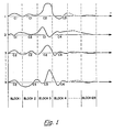
- FIG. 1 is a graphical representation of transient signals used before analysis in obtaining the probability-weighted vector quantised sets of linear prediction coefficients of a recursive filter.
- FIG. 2 shows graphically the distribution of clusters for four of the waveforms of FIG. 1.
- FIG. 3 shows the probability of a transition from one cluster in one block to one of the possible clusters of the next successive block.
- FIG. 4 shows the cumulative probability of a transition from one cluster of one block to one of the possible clusters in the next successive block.
- FIGs. 5A and 5B show a cluster transition probabilities and cumulative transition probabilities, respectively, for a different probability distribution than assumed for FIGs. 3A - 3D and 4A - 4D, respectively.
- FIG. 6 shows in block diagram form apparatus for selecting clusters from cumulative probability values to successive blocks.
- FIG. 7 illustrates the coefficients of clusters in a coefficient memory.
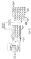
- FIG. 8 is a block diagram of a synthesizer embodying this invention.
- FIG. 9 illustrates a sequence of transition matrices.
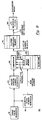
- FIG. 10 is a flow diagram of the steps used in synthesizing a signal in accordance with this invention.
- FIG. 11 is a flow diagram showing the steps for obtaining the clusters utilized in an embodiment of this invention.
- each signal waveform being produced for each closing.
- each waveform could be one period of the cavitation noise produced by a rotating propeller.
- the waveforms may be LPC analyzed to establish period starts by choosing as the start of the period that starting point which results in the minimum number of total clusters by a succession of LPC analyses using different cycle start times.
- the waveform of the analog signals produced by each closing of the hatch cover or propeller period will in general be different, the total number of different sets of coefficients which are obtained from LPC analysis of all the waveforms will be reduced in accordance with the method of this invention.
- a step toward achieving the goal of additional data compression can be taken by using vector quantization.
- vector quantization it is recognized that if the LPC coefficient sets are modified slightly, then some additional distortion will result,but that if the modification is small, then the resulting distortion will be minor.
- the measure of distortion which is utilized is related to subjective perception and is the likelihood ratio distortion measure. This measure is calculated by taking the ratio of the additional modeling error incurred by the use of a non-optimal modeling filter to that minimum error incurred by the use of the optimum filter. For any LPC coefficient set, this residual modeling error is calculated as where r a (k) is the autocorrelation of the filter coefficients a(k) which can be expressed in its un-normalized form as where p is the number of modelling filter coefficients.
- r x (k) is the data autocorrelation function; where N is the number of samples in a block of the signal being analyzed.
- the residual modeling error is E ⁇ p .
- E ⁇ p is the residual error from the optimal set of coefficients.
- a ⁇ is the optimal set of coefficients for the block, and A is one of the sets of coefficients (clusters) selected for each previous block. Typical values for D(A, A ⁇ ) are in the range of 0.5-2. These values produce synthesized signals in which the distortion is sufficiently low for the synthesized sound to be a useful replica of the original sound from which the data was obtained for the synthesis procedure.
- a process which replaces each signature data block with a cluster such that the distortion is less than a predetermined threshold. If the representation of a data block by the LPC coefficients of any of the previously determined clusters cannot produce a distortion less than the threshold, then a new cluster based on the data block being examined is established. If the threshold is not exceeded, then the cluster producing the least representation distortion is utilized.
- the result of this vector quantization process is a set of clusters, that is, a group of data blocks is represented by clusters C i , where C i ⁇ ⁇ a i i ,...,a p i ⁇ where a k i is the kth coefficient of the ith cluster.
- a cavitation signature was acceptably vector quantized using 18 coefficient sets to represent 512 blocks of data. This is a compression ratio of nearly 30:1 over that of straightforward LPC analysis. Also, the ratio is limited by the length of the signature record being analyzed since the number of clusters required does not grow linearly with record length. These 18 clusters form the set upon which further modeling abstraction by Markov processes can be accomplished. Specifically, the mapping of the data blocks into clusters can be displayed in a cluster observation sequence. The objective of Markov signature analysis is to produce a probabilistic model which accurately describes the time evolution of the signature process across cluster assignments.
- the waveforms shown in FIG. 1 are assumed to be reasonably close to the beginning of a period at the corresponding times.
- An LPC analysis on each waveform as described in the European Patent No. 0 209 336 is performed on blocks 1 - 128, where, if it is assumed that each block is 8 milliseconds in time duration, that the total time duration of the waveform to be analyzed is approximately one second, and that the number N of waveforms is ten, then 1280 sets of coefficients will be required i.e. one set of coefficients is produced from each block.
- the number of sets of coefficients will be significantly larger (sixty times in this example) and substantial memory must be utilized in order to digitally store each coefficient of each of the sets as in the referenced application.
- the sets are vector quantized so that the preceding illustration of 1280 sets of LPC coefficients for the ten waveforms are represented by a smaller number of sets (clusters) of coefficients.
- the sets of coefficients which can be replaced by one cluster are determined by the allowable limit on distortion where the threshold value is evaluated by the likelihood ratio distortion measure, as determined by the equation given hereinbefore.
- the 1280 sets of coefficients may be substantially reduced.
- Each of the waveforms 1, 2,..., N of FIG. 1 are shown divided into eight millisecond blocks labeled 1, 2, 3,..., 128.
- Each block of each waveform when subjected to the LPC analysis produces a set of coefficients.
- the vector quantizing of these sets provides clusters (representative sets of LPC coefficients) less in number than the possible 128 sets of coefficients for each waveform 1,--,N.
- the sets of coefficients for blocks 1 and 2 can be represented by one set of coefficients C1, where C1 are the coefficients calculated for block 1, the calculations of coefficients being performed by the LPC analysis.
- FIGS. 2A-2D show the distribution of clusters C1-C4 for each block 1-4 for each waveform 1-3, and N, respectively.
- FIGS. 2A-2D show that block 1 of each waveform has calculated LPC coefficients which have been replaced by the coefficients in either cluster C1 or cluster C2, whereas block 2 has calculated LPC coefficients which have been replaced by the coefficients of clusters 1, 2, or 3.
- the algorithm which has been used in the preferred embodiment of this invention is a clustering algorithm, which differs from those of the prior art and is shown in the flow diagram of Figure 11.
- the program requires, as an input the index of the initial block to be used to start the distortion analysis as well as the cluster formation distortion threshold, the number of blocks to be analyzed, the block duration, and the number of LPC coefficients. With these inputs the analysis can be limited to any contiguous sequence of blocks in the data.
- the algorithm begins by storing the first block LPC coefficient autocorrelation function (ACF) data in memory. The next block of sampled data is retrieved from memory and the LPC coefficient ACF for this block is calculated, as well as the ACF of the sample data.
- ACF LPC coefficient autocorrelation function
- the representation distortion incurred by using the first set of LPC coefficients instead of the optimal set derived by Levenson recursion is calculated. If this distortion exceeds the cluster establishment threshold, then a new cluster is established, which is represented by the LPC coefficients of the new data block. In addition, the LPC coefficient ACF for the new cluster is stored in memory. If the distortion does not exceed the limit, then the data block is assigned to the first cluster. In an iterative fashion this process is repeated. Each sampled data block is read from the memory and the process of calculating the distortion incurred by using each previously established cluster is calculated. If the cluster establishment threshold is exceeded by each existing cluster, then a new cluster is established and coefficient data is again read into memory.
- the data block is assigned to the cluster which incurs the least representation distortion.
- the LPC gain value, the block index, and the cluster assignment are read to memory so that synthesis of the vector quantized signature can be accomplished. The process is continued until all data blocks have been examined.
- the LPC coefficients for each cluster are read in index fashion to memory also for use in synthesis. It is noted that the number of clusters established by this algorithm is largely a function of the chosen cluster establishment threshold. If the maximum number of clusters allowed is exceeded before all the data is examined, then the algorithm stops and a retry with a higher cluster establishment threshold is dictated. In practice, subsequent passes with successively lower establishment thresholds are conducted until the desired number of clusters is obtained.
- This algorithm has proven extremely effective. For example, it required only fcur minutes to execute a single pass on 512 data blocks of eight millisecond duration, each containing 128 samples. It has been found that all 512 data blocks representing eight seconds of actual sound can be represented by less than two dozen coefficient sets for all of the long-term non-stationary signals examined.
- a transition matrix is a matrix of elements P k (i, j), where P k (i,j) is the probability of a transition from cluster i at block k to cluster j at block k+1.
- the initial state occupancy vector (each state being associated with a cluster) is P o (i,j).
- FIGS. 3A-3D there are shown the transition probability matrices for the transitions between one cluster to the same or a different cluster when it is desired to synthesize the waveform for the next succeeding block from a present block.
- FIGS. 2A-2D for the transition from the cluster representing block 1 to the cluster representing block 2, it is seen that for block 1 the cluster is C1 for waveforms 1 and 2 with a transition to cluster C1 for waveform 1 and a transition from cluster C1 to cluster C2 for waveform 2.
- Waveforms 3 and N are seen to have cluster C2 during block 1 with a cluster C2 for block 2 of waveform 3 and a cluster C3 for block 2 of waveform N.
- the cumulative probability matrix P k (i,j) consists of the accumulated probability densities, where k represents the data block.
- FIGS. 4A-4D are obtainable directly from each of the transition probability matrixes of FIGS. 3A-3D.
- Each column of a row of the transition probability matrix of FIG. 3 should serially accumulate probability densities as indicated in FIG. 4.
- FIG. 4 is utilized in the synthesis procedure.
- the cluster transition from one block to the succeeding block given a particular cluster representing the one block is determined in accordance with the probability matrix. For example, referring to FIG. 4B, it is assumed that block 1 utilized cluster C2 in the synthesis procedure. Whether block 2 utilizes cluster C2 or C3 in the synthesis procedure is determined by the random number generator to be discussed subsequently.
- block 2 will utilize the cluster C2 as the set of coefficients which is applied to the LPC filter during the time period corresponding to block 2.
- the random number generator had produced a number greater than .5 and equal to or less than 1, then the cluster C3 would have been utilized during the time allocated to block 2 to generate the synthesized signal. It will be apparent to those skilled in the art that the probabilities associated with FIGS. 3A-3D and 4A-4D as well as the relative frequency of occurence of clusters are dependent upon the number of clusters which are possible in the transition from one block to the next successive block.
- FIG. 3B shows the cumulative probability matrix corresponding to the transition probability matrix of FIG. 5A which when utilized in conjunction with the random number generator selects with equal probability which of the clusters C1-C4 will be utilized in the svnthesis of the signal during block 2.
- FIG. 6 represents the cumulative probability matrices for two successive blocks, block K and block K+1 in more general terms than that illustrated in FIGS. 4 and 5.
- FIG. 6 is also a representation of how the memory sectors 68, 69 which store and provide cluster data for each block K, (K+1), respectively, might be organized. It is assumed that a pointer 61 selects row 1 of a sector 68 of memory allocated to block K. The selection of row 1 provides cluster 5 for use in the LPC synthesis of block K.
- the LPC coefficients are contained in a memory 70 illustrated in FIG. 7 where the cluster number 5 designates row 5 in memory 70 which contains the LPC coefficients a 0 5 ,....a n 5 .
- Pointer 7 can be structured in the form of a ROM memory.
- Pointer 61 applied to row 1 also provides the cumulative probabilities P 11 ,..., P 15 which are provided to a comparator 62, which has another input from a pseudo random generator 63. If it is assumed that the random number provided by generator 63 falls between the cumulative probability values P12 and P13 inclusive, the comparator will provide an output corresponding to column 3, which is provided as a pointer 64 to row 3 of the memory segment corresponding to block (K+1). Pointer 64 will, at the time corresponding to block (K+1), provide cluster 25 for block (K+1) and also provide all the cumulative probability values P 31 ',...,P 36 ' to the comparator 65 for selection of one cluster for a time corresponding to block (K+2).
- a block diagram of the Markov synthesizer 80 is shown in FIG. 8.
- a timing pulse generator 81 produces a pulse every T milliseconds corresponding to a block time, where T has been chosen in this application to be 8 milliseconds.
- the pulse is provided to the pseudo random number generator 63 and to a sequential block number generator 82.
- the block number generator 82 selects a block address in sequential fashion which determines which block memory sector (such sectors 68, 69 of FIG. 6) is selected in block memory 83.
- a cluster number contained within the sector of memory 82 corresponding to block K is selected and the pdinter for block K is read out of memory 83 into the cluster coefficient memory 70 of FIG. 7.
- the cumulative probabilities provided by the same sector are provided to comparator 62, whose other input is provided by random number generator 63, to provide the cluster number and cumulative probabilities of block (K+1), and so on.
- the LPC coefficients for block K contained within memory 70 are selected by the cluster number from memory 83 block K and provided to a noise-excited LPC recursive synthesizer filter 84, described in detail in European Patent No. 0 209 336 which provides at its output the desired transient synthesized signature.
- a pseudo-random observation sequence must be generated from the Markov model discussed in the background section.
- This model is essentially a time varying Markov chain which consists of a set of states, an initial probability vector, and a set of transition matrices as shown in FIG. 9.
- Each matrix consists of rows and columns of transition probabilities, for example P ij in the K th matrix indicates the probability of entering row j on block K+1 given that the generator is in block i on block K.
- the entries are, therefore, discrete probability densities.
- Each row in addition contains an entry for the cluster set pointer. If the row is selected, then this entry points to the set of LPC coefficients to be used to synthesize the signal for block K.
- FIGs. 10 and 11 are flow diagrams of the synthesis and analysis process, respectively, of this invention which present in a different form the process steps described in the preceding specification.
- FIG. 10 illustrates, as a flow diagram, a method for synthesizing a signal from clustered linear prediction coded coefficients of blocks for the recursive filter, comprising the steps of:
Landscapes
- Engineering & Computer Science (AREA)
- Physics & Mathematics (AREA)
- Acoustics & Sound (AREA)
- Multimedia (AREA)
- Theoretical Computer Science (AREA)
- General Engineering & Computer Science (AREA)
- Health & Medical Sciences (AREA)
- Audiology, Speech & Language Pathology (AREA)
- General Health & Medical Sciences (AREA)
- Compression, Expansion, Code Conversion, And Decoders (AREA)
- Electrophonic Musical Instruments (AREA)
Claims (10)
- Procédé de synthèse d'un signal souhaité, comprenant l'application d'un signal de bruit aléatoire comme entrée d'un filtre récursif (84) ayant une série de valeurs de coefficient qui déterminent la sortie du filtre (84), tout en utilisant, en tant que série de valeurs de coefficient du filtre (84) au cours de chacun d'une séquence de temps de blocs (T) qui correspond à la durée du signal souhaité, une série sélectionnée de coefficients de codage prédictif linéaire (LPC) (a0, ..., an), que série de coefficients LPC (a0, ..., an) étant sélectionnée à partir d'une pluralité de séries stockées (70), et appliqué eau filtre (84),
caractérisé en ce que la sélection et l'application au filtre (84) de chaque série de coefficients LPC (a0, ..., an) comprend les étapes suivantes:génération (81, 63) d'une valeur de probabilité;comparaison (62) de la valeur de probabilité générée avec une série sélectionnée de valeurs de probabilité cumulatives (Pij) provenant des probabilités de transition entre les séries stockées, pour le signal souhaité, et détermination de la valeur de probabilité cumulative (Pij) indiquées par la comparaison selon un critère prédéterminé ;sélection d'une série respective des séries stockées (70) correspondant à la valeur de la probabilité cumulative (Pij) indiquée, chacune des valeurs de probabilité cumulative (Pij) étant associée à une série respective parmi les séries stockées (70);application de la série stockée sélectionnée (a0, ..., an) au filtre récursif (84) pendant la durée d'un temps de bloc (T) ; etsélection, en fonction de ladite valeur de probabilité cumulative indiquée (Pij), d'une série suivante de valeurs de probabilité cumulatives (Pij) pour la comparaison avec une valeur de probabilité générée ensuite (63). - Procédé selon la revendication 1, caractérisé en ce que chacune de ladite série de valeurs de probabilité cumulatives (Pij) est constituée à partir d'une rangée de valeurs de probabilité de transition dans une matrice stockée respective de valeurs de probabilité de transition, une matrice stockée de valeurs de probabilité de transition étant utilisée pour chaque temps de bloc (T) dans ladite séquence, et le nombre de rangées dans la seconde de chaque paire de matrices voisines en séquence étant égal au nombre de colonnes dans la première matrice de la paire.
- Procédé selon la revendication 2, caractérisé en ce qu'une seule série de valeurs de probabilité cumulatives est prévue, à partir de laquelle une première des séries stockées (70) de coefficients LPC peut être déterminée, le nombre de valeurs dans ladite seule série étant égal au nombre de rangées dans la matrice stockée pour le premier temps de bloc (T) dans la séquence.
- Procédé selon l'une quelconque des revendications précédentes, caractérisé en ce que l'étape de comparaison (62) de la valeur de probabilité générée et de détermination de la valeur de probabilité cumulative (Pij) comporte la sélection, à partir de la série sélectionnée de valeurs de probabilité cumulatives (Pij), de la plus petite valeur qui n'est pas inférieure à la valeur de probabilité générée.
- Procédé selon l'une quelconque des revendications précédentes, caractérisé en ce que l'étape de sélection d'une série respective des séries stockées (70) comporte l'accès aux séries stockées (70) avec un pointeur (Nc) associé à la valeur de probabilité cumulative indiquée (Pij).
- Procédé selon l'une quelconque des revendications précédentes, caractérisé en ce que les séries stockées (70) de coefficients LPC (a0, ..., an) et les séries de valeurs de probabilité cumulatives sont utilisées par un traitement comprenant les étapes suivantes:(i) utilisation d'une multiplicité de signaux à analyser, chaque signal à analyser ayant une durée égale à la durée du signal souhaité, et tous les signaux à analyser ayant les mêmes caractéristiques brutes, qui apparaissent sensiblement aux mêmes instants dans les signaux;(ii) échantillonnage et division de chaque signal à analyser en un nombre identique de blocs d'échantillons, chaque bloc occupant un temps de bloc (T) du signal souhaité;(iii) calcul d'une série de coefficients LPC pour le filtre récursif (84), pour chaque bloc de chacun de la multiplicité de signaux;(iv) sélection, à partir des séries calculées de coefficients LPC, d'un nombre réduit de séries calculées pour servir en tant que séries stockées (70) par :(a) sélection d'une première série à partir des séries calculées et stockage de la première série sélectionnée,(b) comparaison d'une autre des séries calculées avec la première série sélectionnée,(c) mise à l'écart de ladite autre série si la différence entre la première série sélectionnée et l'autre série n'excède pas une limite de distorsion permise, ou sélection et stockage de ladite autre série si ladite différence excède la limite de distorsion permise,(d) comparaison d'une autre des séries calculées avec les séries stockées sélectionnées et mise à l'écart de l'autre série si la différence entre l'autre série et l'une quelconque des séries stockées sélectionnées n'excède pas la limite de distorsion permise, ou sélection et stockage de ladite autre série si les différences respectives entre ladite autre série et toutes les séries stockées sélectionnées excède la limite de distorsion permise, et(e) répétition de l'étape (d) jusqu'à ce que chacune des séries calculées ait été, soit écartée, soit sélectionnée et stockée;(v) détermination d'une séquence respective des séries stockées correspondant à chaque signal à analyser;(vi) calcul, pour chaque paire voisine de blocs dans la séquence de blocs en laquelle les signaux à analyser sont divisés, de la probabilité de transition entre chaque série stockée possible de coefficients LPC pour le premier bloc séquentiellement dans la paire, et chaque série stockée possible de coefficients LPC pour le second bloc séquentiellement dans la paire; et(vii) calcul, pour chaque paire voisine de blocs, à partir des probabilités de transition calculées pour cette paire, d'une valeur de probabilité cumulative (Pij) pour chaque probabilité de transition calculée.
- Procédé selon la revendication 6, caractérisé en ce que les probabilités de transition pour chaque paire voisine de blocs sont stockées sous la forme d'une matrice, et une matrice correspondante de valeurs de probabilité cumulatives est calculée à partir de chaque matrice de probabilités de transition.
- Procédé selon la revendication 6 ou 7, caractérisé en ce que les valeurs de probabilité d'état initial, pour des séries possibles des séries stockées sélectionnées de coefficients LPC pour le premier bloc dans ladite séquence de blocs, sont calculées, et des valeurs de probabilité cumulatives à l'état initial sont calculées à partir des valeurs de probabilité à l'état initial.
- Appareil pour synthétiser un signal souhaité, comprenant:un filtre récursif (84);un moyen pour appliquer un signal de bruit aléatoire sous forme d'entrée au filtre récursif (84);un moyen (70) pour appliquer au filtre (84), pour chacun d'une séquence de temps de bloc (T), une série sélectionnée de coefficients (a0, ..., an) de codage prédictif linéaire (LPC), la séquence de temps de bloc (T) correspondant à la durée du signal souhaité, et le filtre (84) étant tel qu'il fournit une sortie déterminée par la série de coefficients LPC qui lui sont appliqués, à la suite de quoi le filtre (84) produit, au cours de la séquence de temps de bloc (T), le signal souhaité en fonction de la séquence appliquée de séries de coefficients LPC; etun moyen (70) pour stocker les séries;caractérisé en ce que le moyen pour appliquer les séries sélectionnées de coefficients LPC comprend:un moyen (81, 63) pour générer une valeur de probabilité;un moyen (81, 82, 83) pour appliquer une série sélectionnée de valeurs de probabilité cumulatives (Pij) provenant des probabilités de transition entre les séries stockées, pour le signal souhaité, au moyen de comparaison (62); etun moyen (62) pour comparer une valeur de probabilité générée avec une série sélectionnée de valeurs de probabilité cumulatives (Pij) déterminant la valeur de probabilité cumulative (Pij) indiquée par la comparaison en fonction d'un critère prédéterminé, et pour sélectionner une série respective des séries stockées de coefficients LPC correspondant à la valeur de probabilité cumulative indiquée (Pij) à appliquer au filtre (84), le moyen (81, 82, 83) pour appliquer une série sélectionnée de valeurs de probabilité cumulatives (Pij) comportant un moyen (68, 69) pour associer chacune des valeurs de probabilité cumulatives (Pij) avec une série respective des séries stockées de coefficients LPC (a0, ..., an) et pour sélectionner, en fonction de la valeur de probabilité cumulative indiquée (Pij), une série suivante de valeurs de probabilité cumulatives (Pij) pour la comparaison avec une valeur de probabilité générée suivante.
- Appareil selon la revendication 9, caractérisé en ce que le moyen pour générer une valeur de probabilité comprend un moyen (81, 63) de génération de nombre pseudo-aléatoire pour chaque temps de bloc (T).
Applications Claiming Priority (2)
| Application Number | Priority Date | Filing Date | Title |
|---|---|---|---|
| US45942090A | 1990-01-02 | 1990-01-02 | |
| US459420 | 1990-01-02 |
Publications (3)
| Publication Number | Publication Date |
|---|---|
| EP0436397A2 EP0436397A2 (fr) | 1991-07-10 |
| EP0436397A3 EP0436397A3 (en) | 1992-09-02 |
| EP0436397B1 true EP0436397B1 (fr) | 1996-10-30 |
Family
ID=23824698
Family Applications (1)
| Application Number | Title | Priority Date | Filing Date |
|---|---|---|---|
| EP90314403A Expired - Lifetime EP0436397B1 (fr) | 1990-01-02 | 1990-12-28 | Synthétiseur de son |
Country Status (4)
| Country | Link |
|---|---|
| EP (1) | EP0436397B1 (fr) |
| JP (1) | JPH03293700A (fr) |
| CA (1) | CA2031965A1 (fr) |
| DE (1) | DE69029030T2 (fr) |
Families Citing this family (3)
| Publication number | Priority date | Publication date | Assignee | Title |
|---|---|---|---|---|
| US6471420B1 (en) | 1994-05-13 | 2002-10-29 | Matsushita Electric Industrial Co., Ltd. | Voice selection apparatus voice response apparatus, and game apparatus using word tables from which selected words are output as voice selections |
| JP4736266B2 (ja) * | 2000-08-09 | 2011-07-27 | ソニー株式会社 | 音声処理装置および音声処理方法、学習装置および学習方法、並びにプログラムおよび記録媒体 |
| EP1944760B1 (fr) | 2000-08-09 | 2009-09-23 | Sony Corporation | Dispositif et procédé de traitement de données vocales |
Family Cites Families (2)
| Publication number | Priority date | Publication date | Assignee | Title |
|---|---|---|---|---|
| FR2510288B1 (fr) * | 1981-07-24 | 1986-10-31 | Labo Cent Telecommunicat | Procede et dispositif de generation de bruits sous-marins, en particulier pour la simulation de bruits sonar |
| AU588334B2 (en) * | 1985-07-18 | 1989-09-14 | Raytheon Company | Digital sound synthesizer and method |
-
1990
- 1990-12-11 CA CA002031965A patent/CA2031965A1/fr not_active Abandoned
- 1990-12-28 EP EP90314403A patent/EP0436397B1/fr not_active Expired - Lifetime
- 1990-12-28 DE DE69029030T patent/DE69029030T2/de not_active Expired - Fee Related
- 1990-12-28 JP JP2409368A patent/JPH03293700A/ja active Pending
Also Published As
| Publication number | Publication date |
|---|---|
| JPH03293700A (ja) | 1991-12-25 |
| DE69029030T2 (de) | 1997-06-05 |
| CA2031965A1 (fr) | 1991-07-03 |
| EP0436397A2 (fr) | 1991-07-10 |
| EP0436397A3 (en) | 1992-09-02 |
| DE69029030D1 (de) | 1996-12-05 |
Similar Documents
| Publication | Publication Date | Title |
|---|---|---|
| US4813074A (en) | Method of and device for segmenting an electric signal derived from an acoustic signal | |
| US4709390A (en) | Speech message code modifying arrangement | |
| US5248845A (en) | Digital sampling instrument | |
| KR0143076B1 (ko) | 다중-요소 신호 코딩 방법 및 장치 | |
| US5740320A (en) | Text-to-speech synthesis by concatenation using or modifying clustered phoneme waveforms on basis of cluster parameter centroids | |
| CA1331221C (fr) | Methode et systeme de transmission de signaux vocaux a debit variable | |
| US4802224A (en) | Reference speech pattern generating method | |
| US5119425A (en) | Sound synthesizer | |
| WO1984002992A1 (fr) | Appareil et procede de traitement et de synthese de signaux | |
| EP0397628A1 (fr) | Procédé pour le positionnement des impulsions d'excitation dans un codeur à prédiction linéaire pour signal vocal | |
| WO1990013887A1 (fr) | Analyseur et synthetiseur de sons musicaux | |
| US4945565A (en) | Low bit-rate pattern encoding and decoding with a reduced number of excitation pulses | |
| US5860062A (en) | Speech recognition apparatus and speech recognition method | |
| KR100257775B1 (ko) | 다중 펄스분석 음성처리 시스템과 방법 | |
| EP0523347B1 (fr) | Algorithme rapide pour l'obtention de prototypes acoustiques pour la reconnaissance automatique de la parole | |
| US5005204A (en) | Digital sound synthesizer and method | |
| CA2241549C (fr) | Synthese de formes d'ondes | |
| EP0436397B1 (fr) | Synthétiseur de son | |
| KR100371977B1 (ko) | 음성처리를위한개선된코드북검색방법 | |
| US4423291A (en) | Method for operating a speech recognition device | |
| EP0843874B1 (fr) | Procede de codage de la parole et appareil de reproduction de la parole codee | |
| US5826231A (en) | Method and device for vocal synthesis at variable speed | |
| EP0209336B1 (fr) | Procédé et synthétiseur digital du son | |
| Shuttleworth et al. | The recognition of musical structures using neural networks | |
| JP2560277B2 (ja) | 音声合成方式 |
Legal Events
| Date | Code | Title | Description |
|---|---|---|---|
| PUAI | Public reference made under article 153(3) epc to a published international application that has entered the european phase |
Free format text: ORIGINAL CODE: 0009012 |
|
| AK | Designated contracting states |
Kind code of ref document: A2 Designated state(s): DE FR GB IT |
|
| PUAL | Search report despatched |
Free format text: ORIGINAL CODE: 0009013 |
|
| AK | Designated contracting states |
Kind code of ref document: A3 Designated state(s): DE FR GB IT |
|
| 17P | Request for examination filed |
Effective date: 19921026 |
|
| 17Q | First examination report despatched |
Effective date: 19941104 |
|
| GRAH | Despatch of communication of intention to grant a patent |
Free format text: ORIGINAL CODE: EPIDOS IGRA |
|
| GRAH | Despatch of communication of intention to grant a patent |
Free format text: ORIGINAL CODE: EPIDOS IGRA |
|
| GRAA | (expected) grant |
Free format text: ORIGINAL CODE: 0009210 |
|
| AK | Designated contracting states |
Kind code of ref document: B1 Designated state(s): DE FR GB IT |
|
| REF | Corresponds to: |
Ref document number: 69029030 Country of ref document: DE Date of ref document: 19961205 |
|
| ITF | It: translation for a ep patent filed | ||
| ET | Fr: translation filed | ||
| PLBE | No opposition filed within time limit |
Free format text: ORIGINAL CODE: 0009261 |
|
| STAA | Information on the status of an ep patent application or granted ep patent |
Free format text: STATUS: NO OPPOSITION FILED WITHIN TIME LIMIT |
|
| 26N | No opposition filed | ||
| PGFP | Annual fee paid to national office [announced via postgrant information from national office to epo] |
Ref country code: FR Payment date: 20001130 Year of fee payment: 11 |
|
| PGFP | Annual fee paid to national office [announced via postgrant information from national office to epo] |
Ref country code: GB Payment date: 20001201 Year of fee payment: 11 |
|
| PGFP | Annual fee paid to national office [announced via postgrant information from national office to epo] |
Ref country code: DE Payment date: 20001211 Year of fee payment: 11 |
|
| PG25 | Lapsed in a contracting state [announced via postgrant information from national office to epo] |
Ref country code: GB Free format text: LAPSE BECAUSE OF NON-PAYMENT OF DUE FEES Effective date: 20011228 |
|
| REG | Reference to a national code |
Ref country code: GB Ref legal event code: IF02 |
|
| PG25 | Lapsed in a contracting state [announced via postgrant information from national office to epo] |
Ref country code: DE Free format text: LAPSE BECAUSE OF NON-PAYMENT OF DUE FEES Effective date: 20020702 |
|
| GBPC | Gb: european patent ceased through non-payment of renewal fee |
Effective date: 20011228 |
|
| PG25 | Lapsed in a contracting state [announced via postgrant information from national office to epo] |
Ref country code: FR Free format text: LAPSE BECAUSE OF NON-PAYMENT OF DUE FEES Effective date: 20020830 |
|
| REG | Reference to a national code |
Ref country code: FR Ref legal event code: ST |
|
| PG25 | Lapsed in a contracting state [announced via postgrant information from national office to epo] |
Ref country code: IT Free format text: LAPSE BECAUSE OF NON-PAYMENT OF DUE FEES;WARNING: LAPSES OF ITALIAN PATENTS WITH EFFECTIVE DATE BEFORE 2007 MAY HAVE OCCURRED AT ANY TIME BEFORE 2007. THE CORRECT EFFECTIVE DATE MAY BE DIFFERENT FROM THE ONE RECORDED. Effective date: 20051228 |