EP0436431A2 - Tieffrequenzhydrophon und Sonarantenne mit solchen Hydrophonen - Google Patents
Tieffrequenzhydrophon und Sonarantenne mit solchen Hydrophonen Download PDFInfo
- Publication number
- EP0436431A2 EP0436431A2 EP19900403741 EP90403741A EP0436431A2 EP 0436431 A2 EP0436431 A2 EP 0436431A2 EP 19900403741 EP19900403741 EP 19900403741 EP 90403741 A EP90403741 A EP 90403741A EP 0436431 A2 EP0436431 A2 EP 0436431A2
- Authority
- EP
- European Patent Office
- Prior art keywords
- ceramic
- hydrophone
- frequency
- low
- electrodes
- Prior art date
- Legal status (The legal status is an assumption and is not a legal conclusion. Google has not performed a legal analysis and makes no representation as to the accuracy of the status listed.)
- Granted
Links
Images



Classifications
-
- G—PHYSICS
- G01—MEASURING; TESTING
- G01V—GEOPHYSICS; GRAVITATIONAL MEASUREMENTS; DETECTING MASSES OR OBJECTS; TAGS
- G01V1/00—Seismology; Seismic or acoustic prospecting or detecting
- G01V1/16—Receiving elements for seismic signals; Arrangements or adaptations of receiving elements
- G01V1/20—Arrangements of receiving elements, e.g. geophone pattern
- G01V1/201—Constructional details of seismic cables, e.g. streamers
-
- B—PERFORMING OPERATIONS; TRANSPORTING
- B06—GENERATING OR TRANSMITTING MECHANICAL VIBRATIONS IN GENERAL
- B06B—METHODS OR APPARATUS FOR GENERATING OR TRANSMITTING MECHANICAL VIBRATIONS OF INFRASONIC, SONIC, OR ULTRASONIC FREQUENCY, e.g. FOR PERFORMING MECHANICAL WORK IN GENERAL
- B06B1/00—Methods or apparatus for generating mechanical vibrations of infrasonic, sonic, or ultrasonic frequency
- B06B1/02—Methods or apparatus for generating mechanical vibrations of infrasonic, sonic, or ultrasonic frequency making use of electrical energy
- B06B1/06—Methods or apparatus for generating mechanical vibrations of infrasonic, sonic, or ultrasonic frequency making use of electrical energy operating with piezoelectric effect or with electrostriction
- B06B1/0644—Methods or apparatus for generating mechanical vibrations of infrasonic, sonic, or ultrasonic frequency making use of electrical energy operating with piezoelectric effect or with electrostriction using a single piezoelectric element
Definitions
- the invention relates to low frequency hydrophones intended for use in towed linear antennas, and to sonar antennas comprising such hydrophones.
- the towed linear antennas by their great length, are used at low frequencies, typically between 50Hz and 2000Hz. They are made up of a large number of hydrophones which must have a high sensitivity, a low self-noise, a pressure resistance beyond 150 bars, a low cost because of their large number, a reduced bulk that is ie dimensions less than 50mm.
- the dynamics of noise is important. For example, sea noise decreases by 30dB between 50Hz and 1000Hz. Consequently, a hydrophone is always followed by a high-pass filter which cuts the noises at very low frequencies and by a filter which levels the sea noise, known as the "whitening" filter.
- the signals picked up by the hydrophone are previously amplified in a pre-amplifier located upstream of the filters; the dynamics of the signals being very important, this preamplifier generally saturates, and the filtering operations are not effective.
- FIG. 1 represents a capillary hydrophone according to the prior art.
- This hydrophone consists of a hollow tube 1 made of piezoelectric ceramic such as PZT, closed at its two ends by two rigid plugs 2 thus delimiting a cavity 3.
- This hydrophone is pressure balanced by means of a capillary tube 4 fixed in one of the plugs and making the internal cavity 3 communicate towards the outside of the hydrophone to equalize the slow variations in pressure.
- This capillary 4 also serves as a mechanical filter and makes it possible to reduce the dynamic range of the signals at the input of the preamplifier.
- a capillary hydrophone is difficult to produce, expensive and too large to be accommodated in towed linear antennas.
- a sparse ceramic is a composite material, one phase of which is piezoelectric (high density, high permittivity and high Young's modulus) and the other phase of which is gas (air). These so-called “dry gap ceramics” are porous and the porosity represents the gaseous volume fraction. According to a known manufacturing process it is also possible to obtain a material with open porosity.
- These ceramics are characterized by an increased hydrostatic sensitivity compared to a compact ceramic and have a lower density than conventional ceramics, for example a PZT ceramic has a density of around 7.3 and a hydrostatic sensitivity of around of 47 picoCoulombs / Newton, while a dry ceramic with a density of about 4 has a sensitivity of about 186 picoCoulombs / Newton.
- the invention relates to a low frequency hydrophone balanced in pressure and behaving like a mechanical filter at low frequencies which does not have the drawbacks of capillary hydrophones, that is to say that it is simple to produce, inexpensive and its dimensions can be adapted to the towed linear antennas, using a saturated gap ceramic resistant to high hydrostatic pressures.
- the low frequency hydrophone according to the invention is characterized in that it comprises at least one lacunar ceramic with open porosity saturated by a viscous fluid, on which electrodes have been deposited.
- the invention also relates to a sonar antenna comprising such hydrophones.
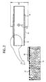
- FIG. 2 represents a sectional view of a lacunar ceramic with open porosity on which electrodes have been deposited.
- the incomplete ceramic 10, with open porosity is in the form of a disc or plate polarized along an axis called "axis 3".
- the direction of polarization of the ceramic is represented by an arrow, 11.
- a deposit was made porous silvering, 12, on the two faces of the ceramic perpendicular to the axis 3 in order to facilitate the subsequent deposition of two metal electrodes 13.
- These electrodes 13, close off part of the pores of the ceramic. Under the effect of an external stress, such as a pressure, perpendicular to the plane of the electrodes, there appears a potential difference VS between the two electrodes 13, due to the appearance of charges of piezoelectric origin.
- lacunar ceramics with open porosity have good resistance to pressure because the open porosity allows the hydrostatic pressure to balance the material and avoids the accumulation of static stresses which generally lead to depolarization of the material.
- FIG. 3 represents the variation of the sensitivity of a saturated lacunar ceramic as a function of the frequency, according to the invention.
- the hydrostatic sensitivity dh of a ceramic is a piezoelectric coefficient which measures the charge on the electrodes for a hydrostatic stress of 1 Newton.
- the hydrostatic sensitivity dh of the ceramic becomes increasing with the frequency so that intrinsically a hydrophone constituted by such a ceramic behaves like a high-pass filter because the material integrates a three-dimensional capillary, with multiple connections, constituted by the pores, in a "skeleton", constituted by the piezoelectric part of the ceramic, which has a certain elasticity.
- the cutoff frequency f1 of the filter depends on the dynamic viscosity of the fluid, ⁇ , the skeletal modulus of elasticity, s, the cross section of the three-dimensional capillary, ⁇ c , and the effective length of the three-dimensional capillary, Le.
- ⁇ the dynamic viscosity of the fluid
- ⁇ the skeletal modulus of elasticity
- s the cross section of the three-dimensional capillary
- ⁇ c the effective length of the three-dimensional capillary
- the pores of the lacunar ceramic have a low acoustic impedance and the dynamic pressure due to an incident acoustic wave penetrates into all the pores and is established without phase shift in the volume of the material. There is therefore a balance of pressures between the outside and inside of the ceramic and the sensitivity of the ceramic is low and equal to dh0
- the pores of the lacunar ceramic have a high acoustic impedance, the skeleton of the ceramic is compressed and the sensitivity of the saturated lacunar ceramic is high and equal to dh M.
- the cut-off frequency f1 can be adjusted by more or less sealing the surface of the ceramic so as to reduce the contact surface of the ceramic with the viscous fluid, in particular by modulating the surface of the electrodes.
- f1 is proportional to ⁇ c / Le2.
- this interior filling fluid is used as viscous fluid for saturate the incomplete ceramic.
- a hydrophone was produced with a disc-shaped ceramic with a disc diameter of 36mm and a height of 10mm saturated with an oil of dynamic viscosity equal to 30 centiPoises.
- the density of the incomplete ceramic is 4 and the porosity is 0.46.
- the cutoff frequency f1 is equal to 600 Hz, the dynamic range dh M / dh0 which only depends on the base material and the porosity, approximately equal to 10 (20dB).
- FIG. 4 shows a hydrophone plate, 40, which is not symmetrical, placed in a cylindrical linear antenna comprising a sealed external sheath, 41, made of polyurethane material for example, this antenna being filled with a viscous fluid 42.
- the hydrophone, 40 is made up of a patchy ceramic, 48, in the form of a plate, saturated by the viscous fluid, 42, for filling the antenna. On the two faces of the ceramic parallel to the longitudinal axis of the antenna were deposited two electrodes, 43.
- the polarization axis, 44, of the ceramic, or axis 3 is perpendicular to the longitudinal axis of the antenna to numb the hydrophone, 40, to the transverse accelerations of the antenna.
- This hydrophone, 40 is held in place by two fixing and decoupling elements, 45, themselves fixed on two carrying cables, 46, arranged along the sheath, 41, and parallel to the axis of the antenna. .
- This hydrophone, 40 is connected to a preamplifier, 47, connected to the electrodes, 43.
- FIG. 5 represents a sectional view of a symmetrical hydrophone, 50, placed in a cylindrical linear antenna, 51, filled with a viscous fluid, 52.
- This hydrophone, 50 is composed of a central metal disc, 53, forming an electrode, on either side of which are fixed two discs, 54, of sparse ceramic with open porosity saturated by the filling fluid of the antenna, such as the normal axis to the surfaces of the discs 53, 54 is parallel to the longitudinal axis of the antenna.
- the hydrophone, 50 is centered in the antenna by two elements, 55, for centering and mechanical decoupling fixed on two carrying cables, 56, arranged parallel to the longitudinal axis of the antenna and symmetrically with respect to this axis.
- each of the two discs, 54, in sparse ceramic is completely covered by an electrode, 57, so that the cut-off frequency f1 is low.
- the ceramic discs, 54, are polarized in a direction parallel to the axis of the linear antenna, the directions of polarization being directed from the outer electrodes, 57, toward the central metal disc, 53.
- the output signal from the hydrophone, 50, is amplified in a preamplifier 58.
- FIG. 6 represents a sectional view of a symmetrical hydrophone placed in a cylindrical linear antenna filled with a viscous fluid, 67.
- This hydrophone comprises two discs 61 separate in sparse ceramic with open porosity saturated by the filling fluid of the antenna and such that on the faces of each of these discs 61 are deposited two electrodes 62 of short length.
- These discs, 61 are such that the axis normal to their surfaces is parallel to the longitudinal axis of the antenna and are polarized in a direction parallel to the axis of the antenna, the directions of polarization being opposite.
- the 4 electrodes 62 are connected to a preamplifier 63 covered by a wire mesh 64 forming a Faraday cage and disposed between the two discs 61 in sparse ceramic.
- Two centering and mechanical decoupling elements 65 hold the ceramic discs 61 and the preamplifier 63 in place in the antenna.
- the surface of the gap ceramics in contact with the viscous fluid is optimized and the electrodes, 62, have a surface as small as possible so that the cut-off frequency f1 is high.
- the hydrophone is made resistant to underwater explosions.
- the invention is not limited to the embodiments precisely described; in particular, the production of a hydrophone with a deficient ceramic saturated by the viscous fluid filling the linear antenna makes it possible to obtain a hydrophone at minimum cost and particularly simple, but any other viscous fluid different from the filling fluid can be used to saturate the incomplete ceramic.
Landscapes
- Physics & Mathematics (AREA)
- Life Sciences & Earth Sciences (AREA)
- Engineering & Computer Science (AREA)
- Acoustics & Sound (AREA)
- Environmental & Geological Engineering (AREA)
- Geology (AREA)
- Remote Sensing (AREA)
- General Life Sciences & Earth Sciences (AREA)
- General Physics & Mathematics (AREA)
- Geophysics (AREA)
- Mechanical Engineering (AREA)
- Transducers For Ultrasonic Waves (AREA)
- Measurement Of Velocity Or Position Using Acoustic Or Ultrasonic Waves (AREA)
Applications Claiming Priority (2)
| Application Number | Priority Date | Filing Date | Title |
|---|---|---|---|
| FR9000077 | 1990-01-05 | ||
| FR9000077A FR2656971B1 (fr) | 1990-01-05 | 1990-01-05 | Hydrophone basse frequence et antenne sonar comportant de tels hydrophones. |
Publications (3)
| Publication Number | Publication Date |
|---|---|
| EP0436431A2 true EP0436431A2 (de) | 1991-07-10 |
| EP0436431A3 EP0436431A3 (en) | 1991-11-06 |
| EP0436431B1 EP0436431B1 (de) | 1994-03-30 |
Family
ID=9392536
Family Applications (1)
| Application Number | Title | Priority Date | Filing Date |
|---|---|---|---|
| EP90403741A Expired - Lifetime EP0436431B1 (de) | 1990-01-05 | 1990-12-21 | Tieffrequenzhydrophon und Sonarantenne mit solchen Hydrophonen |
Country Status (4)
| Country | Link |
|---|---|
| US (1) | US5144597A (de) |
| EP (1) | EP0436431B1 (de) |
| DE (1) | DE69007766T2 (de) |
| FR (1) | FR2656971B1 (de) |
Cited By (1)
| Publication number | Priority date | Publication date | Assignee | Title |
|---|---|---|---|---|
| EP0616989A1 (de) * | 1993-03-26 | 1994-09-28 | Bayer Ag | Imprägnierungsemulsion für mineralische Baustoffe |
Families Citing this family (8)
| Publication number | Priority date | Publication date | Assignee | Title |
|---|---|---|---|---|
| US5646470A (en) * | 1994-04-01 | 1997-07-08 | Benthos, Inc. | Acoustic transducer |
| DE19538678C2 (de) * | 1995-10-17 | 1998-12-10 | Endress Hauser Gmbh Co | Anordnung zur Überwachung eines vorbestimmten Füllstands einer Flüssigkeit in einem Behälter |
| FR2776161B1 (fr) | 1998-03-10 | 2000-05-26 | Thomson Marconi Sonar Sas | Antenne d'emission acoustique annulaire demontable |
| US6438070B1 (en) | 1999-10-04 | 2002-08-20 | Halliburton Energy Services, Inc. | Hydrophone for use in a downhole tool |
| FR2800229B1 (fr) | 1999-10-22 | 2002-04-05 | Thomson Marconi Sonar Sas | Transducteur acoustique sous-marin a large bande |
| FR2809580B1 (fr) | 2000-05-26 | 2002-08-30 | Thomson Marconi Sonar Sas | Transducteur electrodynamique pour acoustique sous-marine |
| US7206258B1 (en) | 2005-04-13 | 2007-04-17 | United States Of America As Represented By The Secretary Of The Navy | Dual response acoustical sensor system |
| DE102018222736A1 (de) * | 2018-12-21 | 2020-06-25 | Atlas Elektronik Gmbh | Unterwasserantenne umfassend einen mit einem Fluid gefüllten Zwischenraum und einen Unterwasser-Schallempfänger |
Family Cites Families (11)
| Publication number | Priority date | Publication date | Assignee | Title |
|---|---|---|---|---|
| BE757591A (fr) * | 1969-11-25 | 1971-03-16 | Thomson Csf | Perfectionnements aux domes de systemes sonars et procede de leur fabrication |
| US5003285A (en) * | 1972-09-08 | 1991-03-26 | The United States Of America As Represented By The Secretary Of The Navy | Transducer array |
| FR2290812A1 (fr) * | 1974-11-08 | 1976-06-04 | Thomson Csf | Transducteur electroacoustique pour immersion profonde |
| FR2589248B1 (fr) * | 1978-02-17 | 1988-01-22 | Thomson Csf | Amelioration des systemes d'autoguidage acoustique de vehicules sous-marins |
| FR2540325A1 (fr) * | 1983-01-28 | 1984-08-03 | Thomson Csf | Hydrophone de vitesse |
| DE3430186A1 (de) * | 1984-08-16 | 1986-02-27 | Siemens AG, 1000 Berlin und 8000 München | Verfahren zur herstellung eines poroesen piezoelektrischen materials und nach diesem verfahren hergestelltes material |
| US4683161A (en) * | 1985-02-28 | 1987-07-28 | Piezo Electric Products, Inc. | Ceramic body with ordered pores |
| FR2615682B1 (fr) * | 1987-05-19 | 1989-07-13 | Thomson Csf | Geophone comportant un element sensible en polymere piezoelectrique |
| US4868447A (en) * | 1987-09-11 | 1989-09-19 | Cornell Research Foundation, Inc. | Piezoelectric polymer laminates for torsional and bending modal control |
| US4876675A (en) * | 1987-09-12 | 1989-10-24 | Ngk Spark Plug Co., Ltd. | Towed piezoelectric cable |
| FR2622333B1 (fr) * | 1987-10-27 | 1990-01-26 | Thomson Csf | Revetement anechoique pour ondes acoustiques |
-
1990
- 1990-01-05 FR FR9000077A patent/FR2656971B1/fr not_active Expired - Lifetime
- 1990-12-21 EP EP90403741A patent/EP0436431B1/de not_active Expired - Lifetime
- 1990-12-21 DE DE69007766T patent/DE69007766T2/de not_active Expired - Fee Related
- 1990-12-27 US US07/634,533 patent/US5144597A/en not_active Expired - Fee Related
Cited By (2)
| Publication number | Priority date | Publication date | Assignee | Title |
|---|---|---|---|---|
| EP0616989A1 (de) * | 1993-03-26 | 1994-09-28 | Bayer Ag | Imprägnierungsemulsion für mineralische Baustoffe |
| US5531812A (en) * | 1993-03-26 | 1996-07-02 | Bayer Aktiengesellschaft | Impregnating emulsion for mineral building materials |
Also Published As
| Publication number | Publication date |
|---|---|
| DE69007766T2 (de) | 1994-07-28 |
| FR2656971B1 (fr) | 1992-09-04 |
| EP0436431A3 (en) | 1991-11-06 |
| FR2656971A1 (fr) | 1991-07-12 |
| DE69007766D1 (de) | 1994-05-05 |
| US5144597A (en) | 1992-09-01 |
| EP0436431B1 (de) | 1994-03-30 |
Similar Documents
| Publication | Publication Date | Title |
|---|---|---|
| EP0142178B2 (de) | Ultraschall-Wandler | |
| EP0436431B1 (de) | Tieffrequenzhydrophon und Sonarantenne mit solchen Hydrophonen | |
| DE2052356C3 (de) | Quarzresonator-Druckmesswertwandler | |
| EP3596825B1 (de) | Säge-resonator mit schichten zur dämpfung parasitärer wellen | |
| EP0194953B1 (de) | Integrierter kapazitiver Sensor für mechanische Grössen und dessen Fabrikationsverfahren | |
| FR2788176A1 (fr) | Dispositif a ondes acoustiques guidees dans une fine couche de materiau piezo-electrique collee par une colle moleculaire sur un substrat porteur et procede de fabrication | |
| EP0939893A1 (de) | Miniaturisiertes photoakustisches spektrometer | |
| EP2267893B1 (de) | Volumenwellenresonator mit teilweise gefüllten Kavitäten | |
| EP0297948A1 (de) | Piezoelektrischer Wandler mit mehreren koaxialen empfindlichen Elementen | |
| FR2811828A1 (fr) | Dispositif a ondes acoustiques comprenant des domaines de polarisation alternee | |
| FR2601824A1 (fr) | Filtre d'onde elastique de surface | |
| FR2650895A1 (fr) | Capteur accelerometrique a poutres vibrant en flexion | |
| FR2635247A1 (fr) | Transducteur piezoelectrique pour generer des ondes de volume | |
| FR2483598A2 (fr) | Allumeur electrique pour munitions | |
| FR3094668A1 (fr) | Assemblage constituant un matériau acoustiquement absorbant | |
| EP0375570B1 (de) | Vorrichtung zur Schwingungensabsorption mit einem piezoelektrischen Element | |
| FR2604588A1 (fr) | Hydrophone piezoelectrique | |
| FR2531217A1 (fr) | Transducteur de mesure de la pression de fluides, en particulier, fluides agressifs, a haute temperature | |
| FR2782568A1 (fr) | Filtre acoustique a deux canaux differents a compensation de rejection | |
| CA2306678A1 (fr) | Hydrophone pour la reception des ondes acoustiques ou sismiques | |
| EP0023162A1 (de) | Elektromechanische Band-Pass-Filter | |
| FR2633139A1 (fr) | Transducteur de signaux d'emission acoustique | |
| EP3979663A1 (de) | Kopfhörer mit geräuschdämpfung | |
| FR3050268A1 (fr) | Capteur de pression capacitif a membrane | |
| FR2598848A1 (fr) | Condensateur de precision a ajustement de la capacite nominale |
Legal Events
| Date | Code | Title | Description |
|---|---|---|---|
| PUAI | Public reference made under article 153(3) epc to a published international application that has entered the european phase |
Free format text: ORIGINAL CODE: 0009012 |
|
| AK | Designated contracting states |
Kind code of ref document: A2 Designated state(s): DE GB IT |
|
| PUAL | Search report despatched |
Free format text: ORIGINAL CODE: 0009013 |
|
| AK | Designated contracting states |
Kind code of ref document: A3 Designated state(s): DE GB IT |
|
| 17P | Request for examination filed |
Effective date: 19911123 |
|
| 17Q | First examination report despatched |
Effective date: 19930723 |
|
| GRAA | (expected) grant |
Free format text: ORIGINAL CODE: 0009210 |
|
| RAP1 | Party data changed (applicant data changed or rights of an application transferred) |
Owner name: THOMSON-CSF |
|
| AK | Designated contracting states |
Kind code of ref document: B1 Designated state(s): DE GB IT |
|
| RIN1 | Information on inventor provided before grant (corrected) |
Inventor name: BESOMBES, JEAN-PIERRE Inventor name: GRAGNOLATI, CLAUDE Inventor name: LAGIER, MICHEL |
|
| ITF | It: translation for a ep patent filed | ||
| REF | Corresponds to: |
Ref document number: 69007766 Country of ref document: DE Date of ref document: 19940505 |
|
| GBT | Gb: translation of ep patent filed (gb section 77(6)(a)/1977) |
Effective date: 19940511 |
|
| PLBE | No opposition filed within time limit |
Free format text: ORIGINAL CODE: 0009261 |
|
| STAA | Information on the status of an ep patent application or granted ep patent |
Free format text: STATUS: NO OPPOSITION FILED WITHIN TIME LIMIT |
|
| 26N | No opposition filed | ||
| PGFP | Annual fee paid to national office [announced via postgrant information from national office to epo] |
Ref country code: DE Payment date: 19951120 Year of fee payment: 6 |
|
| PGFP | Annual fee paid to national office [announced via postgrant information from national office to epo] |
Ref country code: GB Payment date: 19951121 Year of fee payment: 6 |
|
| PG25 | Lapsed in a contracting state [announced via postgrant information from national office to epo] |
Ref country code: GB Effective date: 19961221 |
|
| GBPC | Gb: european patent ceased through non-payment of renewal fee |
Effective date: 19961221 |
|
| PG25 | Lapsed in a contracting state [announced via postgrant information from national office to epo] |
Ref country code: DE Effective date: 19970902 |
|
| PG25 | Lapsed in a contracting state [announced via postgrant information from national office to epo] |
Ref country code: IT Free format text: LAPSE BECAUSE OF NON-PAYMENT OF DUE FEES;WARNING: LAPSES OF ITALIAN PATENTS WITH EFFECTIVE DATE BEFORE 2007 MAY HAVE OCCURRED AT ANY TIME BEFORE 2007. THE CORRECT EFFECTIVE DATE MAY BE DIFFERENT FROM THE ONE RECORDED. Effective date: 20051221 |