EP0436743A1 - Verfahren und vorrichtung zur regelung der rotierenden ringeinheit einer feinspinnmaschine oder ähnlichem - Google Patents
Verfahren und vorrichtung zur regelung der rotierenden ringeinheit einer feinspinnmaschine oder ähnlichem Download PDFInfo
- Publication number
- EP0436743A1 EP0436743A1 EP19900911875 EP90911875A EP0436743A1 EP 0436743 A1 EP0436743 A1 EP 0436743A1 EP 19900911875 EP19900911875 EP 19900911875 EP 90911875 A EP90911875 A EP 90911875A EP 0436743 A1 EP0436743 A1 EP 0436743A1
- Authority
- EP
- European Patent Office
- Prior art keywords
- rotational speed
- ring
- rotary member
- spindle
- ring rotary
- Prior art date
- Legal status (The legal status is an assumption and is not a legal conclusion. Google has not performed a legal analysis and makes no representation as to the accuracy of the status listed.)
- Withdrawn
Links
- 238000000034 method Methods 0.000 title claims abstract description 36
- 238000009987 spinning Methods 0.000 title claims description 125
- 230000007246 mechanism Effects 0.000 claims abstract description 41
- 238000007378 ring spinning Methods 0.000 claims abstract description 6
- 239000004753 textile Substances 0.000 claims description 14
- 238000004804 winding Methods 0.000 claims description 14
- 230000000052 comparative effect Effects 0.000 claims description 5
- 230000000712 assembly Effects 0.000 claims description 3
- 238000000429 assembly Methods 0.000 claims description 3
- 230000009467 reduction Effects 0.000 claims description 2
- 230000008859 change Effects 0.000 description 9
- 238000010586 diagram Methods 0.000 description 9
- 125000006850 spacer group Chemical group 0.000 description 5
- 241001589086 Bellapiscis medius Species 0.000 description 4
- 238000004519 manufacturing process Methods 0.000 description 4
- 239000000463 material Substances 0.000 description 4
- 239000000919 ceramic Substances 0.000 description 3
- 239000000835 fiber Substances 0.000 description 3
- 238000007667 floating Methods 0.000 description 3
- 239000010410 layer Substances 0.000 description 3
- 238000005299 abrasion Methods 0.000 description 2
- 230000001133 acceleration Effects 0.000 description 2
- 230000015572 biosynthetic process Effects 0.000 description 2
- 230000004907 flux Effects 0.000 description 2
- 238000002360 preparation method Methods 0.000 description 2
- 238000003825 pressing Methods 0.000 description 2
- 230000001846 repelling effect Effects 0.000 description 2
- 230000035939 shock Effects 0.000 description 2
- 229920002994 synthetic fiber Polymers 0.000 description 2
- 229910000838 Al alloy Inorganic materials 0.000 description 1
- OKTJSMMVPCPJKN-UHFFFAOYSA-N Carbon Chemical group [C] OKTJSMMVPCPJKN-UHFFFAOYSA-N 0.000 description 1
- 229920000049 Carbon (fiber) Polymers 0.000 description 1
- 229920000742 Cotton Polymers 0.000 description 1
- 229910000881 Cu alloy Inorganic materials 0.000 description 1
- XEEYBQQBJWHFJM-UHFFFAOYSA-N Iron Chemical group [Fe] XEEYBQQBJWHFJM-UHFFFAOYSA-N 0.000 description 1
- 239000004642 Polyimide Substances 0.000 description 1
- 239000004917 carbon fiber Substances 0.000 description 1
- 239000011247 coating layer Substances 0.000 description 1
- 238000001514 detection method Methods 0.000 description 1
- 239000000428 dust Substances 0.000 description 1
- 230000000694 effects Effects 0.000 description 1
- 229920006351 engineering plastic Polymers 0.000 description 1
- 239000000945 filler Substances 0.000 description 1
- 239000012530 fluid Substances 0.000 description 1
- 239000011810 insulating material Substances 0.000 description 1
- 229910052751 metal Inorganic materials 0.000 description 1
- 239000002184 metal Substances 0.000 description 1
- 239000007769 metal material Substances 0.000 description 1
- VNWKTOKETHGBQD-UHFFFAOYSA-N methane Chemical compound C VNWKTOKETHGBQD-UHFFFAOYSA-N 0.000 description 1
- 239000010445 mica Substances 0.000 description 1
- 229910052618 mica group Inorganic materials 0.000 description 1
- 239000004033 plastic Substances 0.000 description 1
- 229920003023 plastic Polymers 0.000 description 1
- 229920001721 polyimide Polymers 0.000 description 1
- 229920000642 polymer Polymers 0.000 description 1
- 239000002952 polymeric resin Substances 0.000 description 1
- 230000008569 process Effects 0.000 description 1
- 229910052761 rare earth metal Inorganic materials 0.000 description 1
- 238000007790 scraping Methods 0.000 description 1
- 238000007789 sealing Methods 0.000 description 1
- 239000010935 stainless steel Substances 0.000 description 1
- 229910001220 stainless steel Inorganic materials 0.000 description 1
- 230000001360 synchronised effect Effects 0.000 description 1
- 239000012209 synthetic fiber Substances 0.000 description 1
- 229920003002 synthetic resin Polymers 0.000 description 1
- BFKJFAAPBSQJPD-UHFFFAOYSA-N tetrafluoroethene Chemical group FC(F)=C(F)F BFKJFAAPBSQJPD-UHFFFAOYSA-N 0.000 description 1
- 230000003313 weakening effect Effects 0.000 description 1
- 229910000859 α-Fe Inorganic materials 0.000 description 1
Images



Classifications
-
- D—TEXTILES; PAPER
- D01—NATURAL OR MAN-MADE THREADS OR FIBRES; SPINNING
- D01H—SPINNING OR TWISTING
- D01H7/00—Spinning or twisting arrangements
- D01H7/02—Spinning or twisting arrangements for imparting permanent twist
- D01H7/52—Ring-and-traveller arrangements
- D01H7/58—Ring-and-traveller arrangements with driven rings ; Bearings or braking arrangements therefor
Definitions
- This invention relates to a method of controlling a rotary spinning ring assembly used in a textile machine including a ring rail and a spindle driving mechanism, such as a ring spinning frame, a ring twisting frame or the like and comprising an annular holder fixed in a horizontal posture on the ring rail, a ring rotary member supported coaxially and rotatably through a bearing mechanism by the holder, a spindle arranged coaxially in an inside space of the ring rotary member and driven by the spindle driving mechanism, and a rotation speed control means for controlling a rotational speed of the ring rotary member, and a related apparatus.
- a spindle driving mechanism such as a ring spinning frame, a ring twisting frame or the like and comprising an annular holder fixed in a horizontal posture on the ring rail, a ring rotary member supported coaxially and rotatably through a bearing mechanism by the holder, a spindle arranged coaxially in an inside space of the
- spinning machine includes all machines having a twisting mechanism in which a twist is applied to a yarn by using a ring and the spindle, including at least a machine for spinning a spun yarn, and further includes a draw twister used for manufacturing a synthetic fiber and a twisting machine used for manufacturing a covered yarn. Further all yarn like materials, such as a natural fiber yarn, a man-made fiber yarn, a metallic wire or the like, can be used as a yarn for the present invention.
- a twisting method using a spindle and ring is an ancient and well known technique.
- the ring is fixed on a ring rail in this conventional twisting technique, and a rotary ring which rotates to stably twist a yarn, even if a rotational speed of the spindle is raised to increase productivity, is known.
- Several bearing mechanisms for rotatably supporting a ring rotary member of a rotary spinning ring assembly using the rotary ring in a spinning operation have been proposed. Namely, Japanese Examined Patent Publication (Kokoku) No. 54-15934 discloses a slide type bearing mechanism having a sliding face; Japanese Examined Patent Publications (Kokoku) No. 54-13528 and No. 54-15528 disclose a pneumatic bearing formed by injecting compressed air; and Japanese Unexamined Patent Publication (Kokai) discloses a bearing using a ball bearing.
- the bearing mechanisms used in the conventional rotary spinning ring assembly have various disadvantages; for example, when a machine such as a spinning frame or the like is stopped and the rotation of the spindle is then stopped, a lowering of a rotational speed of the ring rotary member is later than a lowering of a rotational speed of the spindle, due to an inertial rotation of the ring rotary member, and thus the ring rotary member may overrun the spindle. This overrun causes a generation of snarls in a yarn being twisted, and a breaking of the yarn may be caused by the snarl upon restarting the spinning operation. Accordingly although the rotary spinning ring assembly is considered to an excellent method by which a high speed rotation of the spindle, can be followed by the rotary spinning ring assembly, such an assembly has not been put to practical use.
- the rotary spinning ring assembly has been widely expected to become a useful means of enabling a high speed rotation of the spindle, but a problem of a control of the rotational speed of the ring rotary member, arising because a rotational speed of the spindle becomes too high occurs also in a twisting operation when all of the spindles in the machine are simultaneously stopped.
- the rotational speed of the ring rotary member is increased in proportion to an increase of a rotational speed of the spindle in the rotary spinning ring assembly, and accordingly, when the rotational speed of the spindle is high, the inertia of the ring rotary member becomes large.
- a rotation speed of the traveller on a portion of the bobbin having a larger diameter of a yarn layer is slightly bigger than that at a portion of the bobbin having a smaller diameter of a yarn layer, and thus a stable winding operation is achieved.
- the ring rotary member has a much higher rotational speed, however, the above balance is lost due to an inertial rotation of the ring rotary member, and a rotational speed of the ring rotary member is synchronized with a maximum rotational speed in a chase of the traveller on the ring rotary member, and thus an irregularity in the spinning tension of the yarn arises.
- a twisting state at each spindle is different, as it is at each stage from a beginning stage to a finishing stage, i.e., a full bobbin stage. Accordingly, to obtain a stable twisting operation at all of the spindles in the machine the rotational speed of the ring rotary member must be controlled at each spindle, i.e., each ring rotary member in the machine. Nevertheless, such a control means has not been proposed.
- the same inventor as of the present application proposed a rotary spinning ring assembly enabling a high rotational speed of the ring rotary member and having a rotational speed control means for controlling the rotational speed of the ring rotary member, in Japanese Unexamined Patent Publication (Kokai) No. 2-74633, and Japanese Patent Application No. 1-107060 filed on April 26, 1990, and claiming a priority of Japanese Patent Application No. 63-282854 filed on November 8, 1988.
- the ring rotary member is rotatably supported through a magnetic bearing including an electrical magnet in at least a portion thereof with a holder.
- a motor having a permanent magnet arranged on a ring rotary member and an armature arranged on a holder is provided.
- the primary object of the present invention is to provide a method of controlling a twisting operation of a rotary spinning ring assembly, which prevents a synchronization of a rotation of a ring rotary member with a rotation of a traveller, an overrun of the ring rotary member when the machine is stopped or the like, for all of the spindles of the machine, and by controlling a rotational speed of the ring rotary member during all the spinning process, when a twisting operation is performed by using the rotary spinning ring assembly.
- the second object of the present invention is to provide a twisting operation controlling apparatus for a rotary spinning ring assembly capable of obtaining the primary object of the present invention.
- the primary object of the present invention is attained by a method of controlling a rotary spinning ring assembly, characterized in that a rotational speed of a ring rotary member and a rotational speed of a spindle are detected, respectively, the two detected rotational speed values are compared, and the rotational speed of the ring rotary member is controlled by a rotational speed control means in such a manner that the rotational speed of a ring rotary member is kept within a range of a predetermined optimum ratio of the rotational speed of the ring rotary member to the rotational speed of the spindle.
- a control program for controlling the rotational speed of the spindle from a start of the manufacture of a yarn package to a completion thereof, to a predetermined rotational speed
- another control program for controlling a rotational speed of the ring rotary member to a rotational speed determined by a predetermined optimum ratio in connection with the control program for controlling the rotational speed of the spindle are provided, whereby the control of the rotational speed of the ring rotary member controlled by an optimum ratio controlling means is performed in such a manner that a difference between the detected rotational speed of the ring rotary member and a target rotational speed of the ring rotary member set in the control program is reduced.
- the programmed control of the rotational speed of the ring rotary member is preferably performed in such a manner that the ring rotary member is rotated at a lower rotational speed than that of a traveller, and the rotation of the ring rotary member is proportionally controlled according to a ring rotary member speed-elevation curve having a speed-elevation ratio which is at least not larger than that of a spindle speed-elevation curve during a period of from a starting time to a time at which the rotational speed of the ring rotary member reaches a maximum rotational speed, the rotational speed of the ring rotary member is reduced and is kept within a region of between 40% and 60% of the rotational speed of the spindle during a period in which a half yarn package is spun, the rotational speed of the ring rotary member is raised before the rotational speed of the spindle is reduced from the maximum rotational speed thereof during a period before the yarn package becomes a full bobbin and in which a yarn breakage becomes larger, the rotational
- a start control in which a start of the rotation of the ring rotary member is applied after a slight time lag from a start of the rotation of the spindle, to ensure a first winding of the yarn on a bobbin. It is possible to apply a suitable winding tension to the bobbin by delaying the start of the rotation of the ring rotary member and thus it is possible to obtain a first winding of the yarn on the bobbin.
- a magnetic bearing can be used as the bearing mechanism.
- the magnetic bearing is constituted by annular magnets coaxially arranged, respectively, on axial and radial opposite faces of the ring rotary member and the holder, with a minute gap therebetween in such a manner that the pole of the annular magnet of the ring rotary member is arranged to be opposite the pole of the annular magnet of the holder having the same magnetic properties as that of the annular magnet of the ring rotary member.
- Each opposite face of the annular magnets may have a profile such the both opposite faces are in contact with each other by at least a portion thereof when the ring rotary member moves in the axial direction thereof toward the holder, and an electromagnet may be used to form at least a plurality of magnets arranged in the annular magnet of the holder.
- the control of the rotational speed of the ring rotary member by the rotational speed controlling means can be performed by controlling an intensity of the magnetic field of the electromagnet and adjusting a gap between the ring rotary member and the holder in the magnetic bearing, to thus control a torque generated by the rotating of the ring rotary member.
- the control of the intensity of the magnetic field of the electromagnet can be performed by changing an intensity or a direction of an electric current.
- a rotary spinning ring assembly in which the ring rotary member is rotatably supported through a bearing mechanism with a holder, wherein the bearing mechanism is formed by an annular permanent magnet arranged on the ring rotary member and an armature arranged on the holder, can be used.
- the control of the rotational speed of the ring rotary member by the rotational speed control means is performed by controlling an electric current supplied to the armature.
- the control of the electric current fed to the armature can be performed by adjusting a value of a frequency, a value of an electric current, an electric voltage or a vector of the electric current.
- a control apparatus of the rotary spinning ring assembly used for attaining the second object of the present invention can be used in a spinning machine such as a ring spinning frame and a ring twisting machine or a draw twister having a ring rail and a spindle driving mechanism, and is an apparatus for controlling each rotary spinning ring assembly of the textile machine including a plurality of the rotary spinning ring assemblies comprising, respectively, an annular holder fixed in a horizontal posture to the ring rail, a ring rotary member supported coaxially and rotatably through a bearing mechanism to the holder, a spindle arranged coaxially in an inner space of the ring rotary member and driven by the spindle driving mechanism, and a rotational speed control means of controlling a rotational speed of the ring rotary member.
- the control apparatus is characterized in that a magnetic bearing is used as the bearing mechanism, the magnetic bearing being constituted by annular magnets coaxially arranged, respectively, on axial and radial opposite faces of the ring rotary member and the holder, with a minute gap therebetween, in such a manner that a pole of the annular magnet of the ring rotary member is arranged to be opposite to a pole of the annular magnet of the holder having the same magnetic properties as that of the annular magnet of the ring rotary member, and the each opposite face of the annular magnets has a profile such that the both opposite faces are in contact with each other by at least a portion thereof, when the ring rotary member moves in the axial direction thereof toward the holder, at least a magnet in a plurality of magnets arranged in the annular magnet of the holder is an electromagnet, and the rotary spinning ring assembly control apparatus is comprised of a ring rotational speed detecting means for detecting a rotational speed of the ring rotary member, a spin
- annular permanent magnet at a region constituting the bearing mechanism of the ring rotary member and arrange an armature in the holder, to form a motor, used instead of the magnetic bearing as the bearing mechanism.
- the rotary spinning ring assembly control apparatus includes a control program setting means for setting a program in such a manner that a rotational speed of the spindle can be changed according to an advance of a formation of a cop over the whole period from the start to the completion, optimum spinning conditions of all the spinning process for the various types of yarn are stored in a program storing means, and a suppressing ratio, which is a target rotational speed ratio of the ring rotary member to the rotational speed of the spindle, is stored in a storing program thereof in such a manner that a variable speed control of the rotational speed of the spindle can be performed according to a package size ratio of the cop obtained by, for example, detecting a stretch length.
- the rotary spinning ring assembly equipped with the magnetic bearing is provided with a permanent magnet arranged in an annular state at a substantially center portion of an outer circumference of the ring rotary member and formed as one body with the ring rotary member and a magnet arranged on a fixed holder surrounding same coaxially in an annular state to the ring rotary member from an outside thereof, wherein the permanent magnet is located opposite to the magnet, with a minute annular air gap therebetween, and with the same poles of the permanent magnet and the magnet are opposite to each other, and accordingly the permanent magnet and the magnet repulse each other, and thus the ring rotary member floats in a non-contact state with the holder, and as a result, the magnetic bearing is formed.
- a part of annular magnets arranged on the holder is constituted by an electromagnet, and since this electromagnet has a component in an axial direction of the holder, an electromagnetic floating force or an electromagnetic absorbing force in the axial direction or an upper and lower direction of the ring rotary member can be changed by changing a value of the electric current or a direction of the electric current supplied to the electromagnet, and the ring rotary member moved in a direction in which the electromagnetic floating force is reduced or the electromagnetic absorbing force is increased, and thus a magnetic pole face of the ring rotary member, through a sliding member or the like, is in contact with a magnetic pole face of the holder.
- the degree of contact pressure can be controlled according to an intensity and a direction of the electric current supplied to the electromagnet of the holder, and accordingly, a braking force can be controlled by changing the contact and friction force.
- the ring rotary member When a magnet force of the ring rotary member and a magnet force of the holder are provide an equivalent support of the ring rotary member, the ring rotary member is fully floating, and thus the magnet bearing is maintained in a noncontact state whereby a rotational speed of the ring rotary member is increased to a maximum rotational speed at which the rotational speed of the ring rotary member reaches the same rotational speed as that of a traveller.
- a rotation of the ring rotary member is controlled by applying a resistance thereto caused by a difference between the magnetic forces of the poles of the magnetic bearing held in the non-contact state.
- the ring rotary member, through the sliding member is in contact with either one of an upper pole or a lower pole of the magnet of the holder and a friction is generated therebetween.
- a rotary spinning ring assembly to which a control of the present invention is applied will be described, before a method of controlling the rotary spinning ring assembly and an apparatus therefor are described.
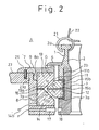
- Figure 2 is a partial axial crosssectional view illustrating an example of the rotary spinning ring assembly controlled in accordance with the present invention.
- a ring rotary member 1 is constituted by a flange rotor 2 having a ring flange portion 2a on which a traveller 21 is slidably rotated, and a lower rotor 3 is connected to the flange rotor 2 by screws 2b.
- the lower rotor 3 is made of a non-magnetic metal material such as an aluminum alloy having a magnetic resistance, a copper alloy, a stainless steel, a carbon group material or the like, and an electrical conductive synthetic material or the like, and thus a leakage of a magnetic flux is cut to a minimum value.
- the ring rotary member 1 is rotatably supported in a holder 7 by a bearing mechanism G, and the holder 7 is inserted into an attaching hole 23a of a ring rail 23 and fixed by a screw 25.
- the bearing mechanism is constituted as follows. Two annular permanent magnets 11 and 12 are fixed through a spacer 15a and 15b into a concave groove 3a formed in the lower rotor 3 of the ring rotary member 1. An outer circumference in a radial direction of the permanent magnets 11 and 15 has a tapered face 11a and 12a having an angle of around 45° relative to an axis thereof, and the magnetic pole of the tapered face 11a and 12a is an N pole.
- the spacer 15b is used as a magnetic sealing means so that a leakage of magnetic flux of the permanent magnets 11 and 12 to the outside, in particular the ring flange portion 2a and the traveller 21, is prevented.
- the holder 7 is constituted with a holder main body 8 and a cover 9 connected thereto by a screw 8a or the like.
- An annular permanent magnet 13 and an annular electromagnet 14 are fixed through a spacer 13a into a concave portion 7a formed in the holder 7.
- Tapered faces 13a and 14a having an angle of 45° relative to an axis of the ring rotary member are formed on an inside circumference in a radial direction of the permanent magnet 13 and the electromagnet 14, in such a manner that both tapered faces form a groove having a substantial V shape, and the tapered faces 13a and 14a and the tapered faces 11a and 12a are arranged in an opposite relationship with a suitable gap therebetween.
- a magnetic pole of the tapered face 13a is the same as the magnetic pole of the tapered face 11a, i.e., an N-pole, and a magnetic pole of the tapered face 14a of the electromagnet 14 is made an N pole by supplying an electric current in a normal direction, to a lead line 14b of the electromagnet 14.
- An intensity of the electromagnet 14 can be adjusted by adjusting the electric current.
- electromagnets having various structures.
- the electromagnets 11, 12 and 13 are an isotropic magnet of a metal, a ferrite (an axidate ceramic), a rare earth element, a rubber, a plastic or the like. Further, if necessary, opposite faces of the permanent magnets 11, 12 and 13 and the electromagnet 14 are provided with a cover such as a sheet, a film or a coating layer, to protect a pole surface.
- This cover may be made of a non-lubricated sliding material having a lower friction coefficient, a superior resistance to abrasion and a superior resistance to heat, e.g., a ceramic, a tetrafluoroethylene including a filler such as a carbon fiber or the like, or a high polymer engineering plastic such as a polyimide, a polyimideamide or the like.
- a non-lubricated sliding material having a lower friction coefficient, a superior resistance to abrasion and a superior resistance to heat
- a ceramic etrafluoroethylene including a filler such as a carbon fiber or the like
- a high polymer engineering plastic such as a polyimide, a polyimideamide or the like.
- a spacer 16 is made of an electrical insulating material such as mica, a high polymer resin, a ceramic or the like, to electrically insulate the electromagnet 14 from the permanent magnet 13.
- a sensor 17 is attached to a holder body 8, and a detecting member 18 for generating a pulse, i.e., a detecting signal, to the sensor 17 is arranged on an outer circumferential face of a lower rotor 3. Accordingly, by providing light and dark portions or notches, the rotational number, i.e., the rotational speed, can be detected by counting the detection signals from the sensor 17.
- the numeral 4 denotes a dust cover, and 22 a yarn supplied from a snarl wire in a ballooning state and wound on a cop (not shown).
- a magnetic pole having substantially the same intensity as that of a tapered face 13a of the permanent magnet 13 is formed on a tapered face 14a of the electromagnet 14 by supplying a suitable electric current through a lead line 14b to the electromagnet 14, and thus the permanent magnets 11 and 12 are floated from the permanent magnet 13 and the electromagnet 14, because the tapered faces 11a and 12a and the tapered faces 13a and 14a repel each other, and is in a noncontact state.
- the ring rotary member 1 can be rotated by an extremely small rotational speed and an energy loss caused by a friction or the like become extremely small, and thus the ring rotary member can be rotated at the high rotational speed by a torque applied from a traveller 21.
- the braking force can be controlled by controlling the amperage and the direction of the electric current supplied to the electromagnet 14, and thus a rotational number of the ring rotary member and a time required to stop the ring rotary member when rotating at a high rotational speed can be controlled.
- FIG. 1 is a block diagram of a controller H relating to the present invention. Note, only two spindles are illustrated in Fig. 1, but in practice all of the spindles in a spinning frame are controlled by the controller H.
- a program storing means 58 is a RAM or ROM, and is provided with a spinning program for all of the spinning process, as determined for each type and yarn count of the various yarns to be spun.
- This spinning program is an optimum range of a spinning tension for each spun yarn, and data of a standard rotational speed of a spindle 53 and the ring rotary member 1, are determined according to a size ratio of a cop and by a stretch length from a starting time to a time at which a full bobbin is wound.
- the rotational number of the spindle can be controlled on the basis of the size ratio by detecting and inputting a position of the ring rail on a linear scale or by bringing the ring rail into sequential contact with a plurality of microswitches, comparing the input data with a preinput program and then changing the rotation of the spindle.
- a data of the rotational number of the ring rotary member 1 is stored as a suppressing ratio K, i.e., a target rotational speed ratio of the ring rotary member 1 to the spindle 53.
- a rotation of the spindle drive motor 51 is controlled such that the spindle 53 is rotated at a predetermined rotational number on the basis of the data sent from the program storing means 58, by a spindle control means 50.
- a spindle drive main shaft 52 is rotated by the spindle drive motor 51, and a rotation of each spindle 53 is obtained through a belt or the like driven by the rotation of the spindle drive main shaft 53.
- the spindle drive main shaft is provided with a rotational number detector 59, such as a tachogenerator, a rotary pulse generator or the like, and a rotational number Rs of the spindle 53 is detected by a rotational number detecting circuit 60 which receives an output of the rotational number detector 59.
- the rotational number Rs of the spindle 53 detected by the rotational number detecting circuit 60 is multiplied by a suppressing ratio K output from a storing means 58, and the obtained data is output as a target rotational number Rj.
- a rotational number detecting circuit 54 detects a rotational number Rr of the ring rotary member 1 by counting pulses output by the sensor 17.
- a comparing means 56 compares the rotational number Rr detected by the rotational speed detecting circuit 54 with the target rotational number Rj output by the multiplying means 57, and outputs an adjusting signal Rh determined on the basis of the difference obtained by the comparison.
- a braking and driving circuit 56 controls an amperage and a direction of the electric current supplied to the electromagnet 14, on the basis of the adjusting signal Rh output from the comparing means 56, and adjusts a braking force in the bearing mechanism G, whereby the rotational number Rr of the ring rotary member 1 is controlled to the target rotational number Rj.
- circuits and means are realized by hardware or a microprocessor including a suitable program.
- Fig. 3 is a diagram of an example of a spinning program of a standard cotton spun yarn having a medium yarn count, e.g., 40's to 60's, and manufactured by a high speed spinning frame equipped with a controller such as a sequencer or the like.
- This spinning program is prepared in such a manner that yarn breakages are kept to a minimum in a period from the rotation of an empty bobbin, or a time at which a yarn is first wound on a bobbin, to size ratio of 0.3, and a period from a size ratio of 0.9 to a full bobbin.
- the present invention aims to provide a controlling means which can control the rotation of the ring rotary member before a control of the rotation of the spindle, and a control program thereof, in such a manner that an optimum spinning condition including an optimum spinning tension in a spinning program for every yarn type and yarn count can be obtained by applying a control of the rotational speed of the ring rotary member by using an electrically controllable rotary spinning ring assembly controlled according to a control of the rotational speed of the spindle.
- the time HS depends on various conditions, such as a total load of the yarn package or the like, use of various braking devices used in the machine, and a rotational speed of the spindle and a torque when the inertial rotation of the ring rotary member starts, but the value of HR can be reduced to around 10 sec by using an inverter and a main motor braking device.
- the value of HS is determined, it is necessary to determine the value of HR as 5 sec to 9 sec.
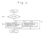
- Fig. 4 is a flow chart illustrating an example of the operation of a comparing means 56 and a braking and controlling circuit 55.
- an electric current supplied to the electromagnet 14 is controlled by multiplying a difference between the rotational number Rr and the target rotational number Rj by a gain ⁇ , to generate an increment F of a braking force caused by the electromagnet 14 in step #12.
- a command of a rotational speed of 0 is applied to a spindle drive motor 51 or a supply of an electric power is switched off and the electric current supplied to the electromagnet 14 is controlled by the braking and controlling circuit 55.
- a direction of the electric current is changed to generate an absorbing power between the permanent magnet 12 and the electromagnet 14 and suddenly increase a braking force of the bearing mechanism, and thus the rotation of the ring rotary member is controlled in such a manner that the ring rotary member is stopped at the same time or before the spindle is stopped.
- a generation of a snarl caused by a yarn winding having an opposite direction can be prevented, and it is possible to perform a suitable control of a spinning tension during a high speed spinning operation.
- a centripetal force is generated by the use of tapered faces 11a to 14a having an angle inclined to an axis thereof, and thus a fluctuation of the axis of the ring rotary member 1 and a waving rotation in a horizontal plane thereof are not generated, whereby a stable rotation can be obtained.
- No yarn breakages occur in a period between first winding the yarn and a period near to a full bobbin when the spinning operation is performed as described in the example, and thus it is possible to obtain a high speed spinning operation. Further, since it is possible to perform a stable spinning operation under a high speed in a period of around a half size ratio, by lowering a rotational speed of the ring rotary member and minimizing a variation of the spinning tension caused by a change of the speed in a chase, the productivity is increased by using less power for rotating the ring rotary member.
- the spinning program is set according to a size ratio based on a stretch length in the above-mentioned example, it is possible to set the spinning program on the basis of a time schedule which is previously known.
- a storing operation of the spinning program to a program storing means 58 may be performed by loading from a suitable external device, or may be input by a keyboard, a digital switch or the like.
- the other circuits can be adopted as a circuit of the controller H.
- the two permanent magnets 11 and 12 used in the example can be made as one body with the ring rotary member 1.
- An electromagnet 14 is used as a magnet arranged on a lower one of the magnets arranged on a holder 7, in the example, but the electromagnet 14 can be used for a magnet arranged on an upper one of the magnet, and further, both magnets in the holder can be electromagnets.
- the pole of the magnet arranged on opposite faces is N in the example, but an S-pole also can be used in this case, and it is possible to use magnets having different poles as an upper magnet and a lower magnet.
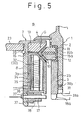
- Fig. 5 is a partial axial crosssectional view of another example B of a rotary spinning ring assembly in accordance with the present invention.
- Members having the same function in the rotary spinning ring assembly shown in Fig. 5 as that of members used in the rotary spinning ring assembly shown in Fig. 2 are given the same reference numeral, and a description thereof is omitted.
- a flange rotor 2 and a lower rotor 3 are connected by a thread 2b and are fixed through a belleville spring 31b by a locknut 31 having a tool engaging groove.
- a notch 18a is provided in a lower end of the lower rotor 3 and a sensor 17 detects the notch 18a and generates a signal denoting a rotational number.
- a holder 7 is attached with a yoke case 34, a plurality of equally spaced holes are arranged in a circumferential direction in the yoke case 34, and a wave guide 35 is accommodated in each hole.
- Electromagnets 32 and 33 having a crosssection of a circular shape or a fan-like shape, and on which a coil is wound, are accommodated in the wave guide.
- the lead lines extend from the electromagnet 32 and 33.
- the numeral 10 denotes a cover, 36 a bottom plate, 37, an end ring, 38 a stop ring, and 39 a spring used for fixing the ring.
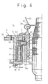
- a permanent magnet 41 adhered to the ring rotary member 1 is formed as an annular plate having a rectangular crosssection, and permanent magnets 42 and 43, and an electromagnet 44 may be arranged in such a manner that a part of an upper side and a lower side, and a side between the upper side and the lower side, form a C letter type crosssection.
- Fig. 7 shows a partial axial crosssection of another example D of the rotary spinning ring assembly in accordance with the present invention.
- a ring rotary member 1 is rotatably supported through a bearing 72 in a holder 7, a motor 71 comprised of a permanent magnet rotator 73 arranged on a substantially center portion in an axial direction in an outer circumferential portion of the ring rotary member 1, and an armature 74 arranged on a substantially center portion is an axial direction in an inner circumferential portion of the holder 7, so that the rotator 73 and the armature 74 are opposite to each other.
- This motor 71 directly drives the ring rotary member 1 and a rotational speed of the ring rotary member 1 can be changed by adjusting a frequency or an amperage of the electric current supplied to the motor 71.
- the numeral 18b denotes a detecting plate having a white portion and a black portion used for detecting a rotational speed thereof by a reflection type sensor 17, 76 is a rebound spring, 77 a spacer, and 78 a stop ring.
- this rotary spinning ring assembly D When using this rotary spinning ring assembly D, it is possible to control the assembly D by adjusting a frequency or an amperage of the electric current supplied to the motor 71 by the braking and controlling circuit 55, and coincide the rotational number Rr of the ring rotary member 1 with the target rotational number Rj.
- a rotational number Nt of a traveller 21 It is possible to calculate a rotational number Nt of a traveller 21 by detecting a delivering speed l of a yarn based on the rotational speed of the spindle and a thickness of a yarn layer on an bobbin. It is also possible to control the rotational number Rr of the ring rotary member 1 so that it does not exceed the rotational number of the traveller 21, on the basis of the above detected value. Note, since a difference between the rotational number Rs of the spindle and the rotational number Nt of the traveller is not large, a maximum value of the rotational number Rr of the ring rotary member may be roughly determined from the following equation. Rs x 0.9 ⁇ Rr
- a control of a rotation of a spindle based on an optimum spinning diagram depending on a yarn type or a yarn count of the yarn to be spun a control of the ring rotary member performed by following the control of the rotation of the spindle to make a ratio between the rotational speed of the spindle and the rotational speed of the ring rotary member an optimum value, an attaining of a maximum rotation of the machine in a minimum time, and an attaining of a stop of the machine in a minimum time
- a preparation of a spinning program whereby a spinning operation is performed at a maximum rotational speed, a maximum value can be attained, and further, it is possible to prevent a synchronization of the rotations of the ring rotary member and the traveller and an overrun of the ring rotary member when stopping the ring rotary member.
- the flange rotor 2 and the lower rotor 3 may be united as one body by pressing one member into another.
- a shape, a dimension, a structure, a material, a number of members used, and an arrangement of the members are optionally determined in accordance with the present invention.
- a control of a rotation of a spindle based on an optimum spinning diagram depending on a yarn type or a yarn count of the yarn to be spun, a control of the ring rotary member performed by the control of the rotation of the spindle to make a ratio between the rotational speed of the spindle and the rotational speed of the ring rotary member an optimum value, an attaining of an maximum rotation of the machine in a minimum time, and an attaining of a stop of the machine in a minimum time can be performed in accordance with the present invention, and accordingly, a preparation of spinning program making a spinning operation performed at a maximum rotational speed a maximum value can be attained, and further, it is possible to prevent a synchronization of the rotations of the ring rotary member and the traveller and an overrun of the ring rotary member when stopping the ring rotary member.
- the method and the apparatus in accordance with the present invention can be applied not only to a spinning frame but also to all textile machines having a twisting mechanism using a ring and a spindle, such as a twisting machine, a draw twister, a twister manufacturing a cover yarn or the like.
Landscapes
- Engineering & Computer Science (AREA)
- Mechanical Engineering (AREA)
- Textile Engineering (AREA)
- Spinning Or Twisting Of Yarns (AREA)
Applications Claiming Priority (2)
| Application Number | Priority Date | Filing Date | Title |
|---|---|---|---|
| JP20212989 | 1989-08-03 | ||
| JP202129/89 | 1989-08-03 |
Publications (2)
| Publication Number | Publication Date |
|---|---|
| EP0436743A1 true EP0436743A1 (de) | 1991-07-17 |
| EP0436743A4 EP0436743A4 (en) | 1992-01-22 |
Family
ID=16452446
Family Applications (1)
| Application Number | Title | Priority Date | Filing Date |
|---|---|---|---|
| EP19900911875 Withdrawn EP0436743A4 (en) | 1989-08-03 | 1990-08-03 | Method and apparatus for controlling rotary ring unit of fine spinning frame or the like |
Country Status (2)
| Country | Link |
|---|---|
| EP (1) | EP0436743A4 (de) |
| WO (1) | WO1991002112A1 (de) |
Cited By (3)
| Publication number | Priority date | Publication date | Assignee | Title |
|---|---|---|---|---|
| EP0443032B1 (de) * | 1989-09-11 | 1996-01-03 | Kabushikigaisha Sekogiken | Stromversorgungsvorrichtung für induktive tasten |
| IT201900019752A1 (it) * | 2019-10-24 | 2021-04-24 | Cogne Macch Tessili S P A | Metodo di controllo di un filatoio per ottenere una messa a punto automatica di tale filatoio |
| WO2023186722A1 (de) * | 2022-03-28 | 2023-10-05 | Maschinenfabrik Rieter Ag | Spinnstelle für eine ringspinnmaschine sowie verfahren zum betreiben einer spinnstelle für eine ringspinnmaschine |
Families Citing this family (2)
| Publication number | Priority date | Publication date | Assignee | Title |
|---|---|---|---|---|
| JPH0879685A (ja) * | 1994-08-31 | 1996-03-22 | Sony Corp | ニア・ビデオ・オン・デマンドシステムにおけるプログラム再生装置 |
| UA44364C2 (uk) * | 1999-06-08 | 2002-02-15 | Горлівське Відкрите Акціонерне Товариство "Концерн Стирол" | Пристрій для проведення тепло-, масообмінних і реакційних процесів |
Family Cites Families (3)
| Publication number | Priority date | Publication date | Assignee | Title |
|---|---|---|---|---|
| JPS61152835A (ja) * | 1984-12-21 | 1986-07-11 | Kanai Hiroyuki | 回転リング |
| JPH01168923A (ja) * | 1987-12-22 | 1989-07-04 | Nippon Mengiyou Gijutsu Keizai Kenkyusho | 回転リングを備えた精紡機の運転制御方法 |
| JPH0686688B2 (ja) * | 1988-09-05 | 1994-11-02 | 博史 山口 | 紡績用回転リングの軸承装置 |
-
1990
- 1990-08-03 EP EP19900911875 patent/EP0436743A4/en not_active Withdrawn
- 1990-08-03 WO PCT/JP1990/000998 patent/WO1991002112A1/ja not_active Ceased
Cited By (3)
| Publication number | Priority date | Publication date | Assignee | Title |
|---|---|---|---|---|
| EP0443032B1 (de) * | 1989-09-11 | 1996-01-03 | Kabushikigaisha Sekogiken | Stromversorgungsvorrichtung für induktive tasten |
| IT201900019752A1 (it) * | 2019-10-24 | 2021-04-24 | Cogne Macch Tessili S P A | Metodo di controllo di un filatoio per ottenere una messa a punto automatica di tale filatoio |
| WO2023186722A1 (de) * | 2022-03-28 | 2023-10-05 | Maschinenfabrik Rieter Ag | Spinnstelle für eine ringspinnmaschine sowie verfahren zum betreiben einer spinnstelle für eine ringspinnmaschine |
Also Published As
| Publication number | Publication date |
|---|---|
| EP0436743A4 (en) | 1992-01-22 |
| WO1991002112A1 (fr) | 1991-02-21 |
Similar Documents
| Publication | Publication Date | Title |
|---|---|---|
| US3785140A (en) | Device for winding threads, particularly textile threads | |
| KR920010283B1 (ko) | 개량된 회전링 방적장치 | |
| US5740666A (en) | Method and system for controlling the rotational speed of a rotary ring member | |
| JPH07502789A (ja) | 糸使用繊維機械のための糸供給装置 | |
| US5009063A (en) | Rotary ring spinning device provided with a ring motor | |
| JPS61206821A (ja) | 回転可能な軸を有する制御可能な電磁式の支承装置を使用する方法 | |
| JPH08512100A (ja) | 精紡機並びにその制御および調整装置 | |
| US2559735A (en) | Strand twisting machine | |
| CN101333712A (zh) | 用于环锭纺纱机或捻线机的设备和导纱环锭以及环锭纺纱或捻线机 | |
| US4516611A (en) | Weft yarn storage unit for jet looms | |
| JP2001500200A (ja) | ポットスピニング装置 | |
| US4689942A (en) | Device and method for assembling threads | |
| EP0963937B1 (de) | Spannungsregelungsverfahren unter Verwendung einer Flusenunterdrückungsvorrichtung | |
| US3434673A (en) | Drive mechanism | |
| US4918911A (en) | Spinning apparatus | |
| EP0933322A2 (de) | Aufwickelvorrichtung für Filamentgarn | |
| WO1991002112A1 (fr) | Procede et appareil de commande d'une unite annulaire rotative de metier a filer ou analogue | |
| EP0310848A1 (de) | Verfahren und Vorrichtung zur Herstellung von Kerngarnen | |
| JPH08324885A (ja) | 光ファイバ心線の巻取り装置 | |
| JPH0729432A (ja) | 二度撚型撚線機 | |
| CN115135824A (zh) | 用于环锭纺纱机或环锭加捻机的卷绕和加捻装置 | |
| JPWO1991002112A1 (ja) | 精紡機等における回転リング装置をコントロールする方法と装置 | |
| EP0475476A1 (de) | Vorrichtung zum Spannungswechselausgleich eines Fadens beim Abwickeln in einer Spulvorrichtung | |
| EP0475484A1 (de) | Vorrichtung zur gleichmässigen Fadenspannung beim Abwickeln in einer Spulvorrichtung | |
| EP1031525B1 (de) | Vorrichtung zum Bremsen eines Fadens oder dergleichen |
Legal Events
| Date | Code | Title | Description |
|---|---|---|---|
| PUAI | Public reference made under article 153(3) epc to a published international application that has entered the european phase |
Free format text: ORIGINAL CODE: 0009012 |
|
| 17P | Request for examination filed |
Effective date: 19910429 |
|
| AK | Designated contracting states |
Kind code of ref document: A1 Designated state(s): CH DE ES FR GB IT LI |
|
| A4 | Supplementary search report drawn up and despatched |
Effective date: 19911202 |
|
| AK | Designated contracting states |
Kind code of ref document: A4 Designated state(s): CH DE ES FR GB IT LI |
|
| RIN1 | Information on inventor provided before grant (corrected) |
Inventor name: YAMAGUCHI, MASASHI Inventor name: YAMAGUCHI, HIROSHI |
|
| 17Q | First examination report despatched |
Effective date: 19940831 |
|
| GRAG | Despatch of communication of intention to grant |
Free format text: ORIGINAL CODE: EPIDOS AGRA |
|
| GRAH | Despatch of communication of intention to grant a patent |
Free format text: ORIGINAL CODE: EPIDOS IGRA |
|
| GRAH | Despatch of communication of intention to grant a patent |
Free format text: ORIGINAL CODE: EPIDOS IGRA |
|
| RAP3 | Party data changed (applicant data changed or rights of an application transferred) |
Owner name: KIMURA, HIROSHI Owner name: YAMAGUCHI, HIROSHI |
|
| STAA | Information on the status of an ep patent application or granted ep patent |
Free format text: STATUS: THE APPLICATION IS DEEMED TO BE WITHDRAWN |
|
| 18D | Application deemed to be withdrawn |
Effective date: 19970603 |