EP0436752A1 - Trennanordnung für optische Interferenzsignale - Google Patents
Trennanordnung für optische Interferenzsignale Download PDFInfo
- Publication number
- EP0436752A1 EP0436752A1 EP90100310A EP90100310A EP0436752A1 EP 0436752 A1 EP0436752 A1 EP 0436752A1 EP 90100310 A EP90100310 A EP 90100310A EP 90100310 A EP90100310 A EP 90100310A EP 0436752 A1 EP0436752 A1 EP 0436752A1
- Authority
- EP
- European Patent Office
- Prior art keywords
- optical
- signal
- light
- interference signal
- optical interference
- Prior art date
- Legal status (The legal status is an assumption and is not a legal conclusion. Google has not performed a legal analysis and makes no representation as to the accuracy of the status listed.)
- Granted
Links
- 230000003287 optical effect Effects 0.000 title claims abstract description 171
- 238000001228 spectrum Methods 0.000 claims abstract description 19
- 230000015654 memory Effects 0.000 claims description 17
- 238000005070 sampling Methods 0.000 claims description 7
- 238000012935 Averaging Methods 0.000 claims 2
- 238000010408 sweeping Methods 0.000 abstract description 2
- 239000000284 extract Substances 0.000 abstract 1
- 230000014509 gene expression Effects 0.000 description 9
- 238000010586 diagram Methods 0.000 description 7
- 230000003595 spectral effect Effects 0.000 description 4
- 238000006243 chemical reaction Methods 0.000 description 2
- 230000004048 modification Effects 0.000 description 2
- 238000012986 modification Methods 0.000 description 2
- 238000010183 spectrum analysis Methods 0.000 description 2
- 230000009466 transformation Effects 0.000 description 2
- 238000010276 construction Methods 0.000 description 1
- 238000000034 method Methods 0.000 description 1
Images


Classifications
-
- G—PHYSICS
- G01—MEASURING; TESTING
- G01J—MEASUREMENT OF INTENSITY, VELOCITY, SPECTRAL CONTENT, POLARISATION, PHASE OR PULSE CHARACTERISTICS OF INFRARED, VISIBLE OR ULTRAVIOLET LIGHT; COLORIMETRY; RADIATION PYROMETRY
- G01J3/00—Spectrometry; Spectrophotometry; Monochromators; Measuring colours
- G01J3/28—Investigating the spectrum
- G01J3/45—Interferometric spectrometry
- G01J3/453—Interferometric spectrometry by correlation of the amplitudes
Definitions
- the present invention relates to an optical interference signal extractor for use in measuring the spectral distribution of light.
- Fig. 1 shows a conventional optical interference signal extractor.
- Reference numeral 10 indicates a light source for emitting light 11 to be measured and 20 an optical interferometer capable of sweeping an optical path difference, that is, capable of continuously changing an optical path difference.
- the optical interferometer 20 is shown to be a Michelson interferometer but may also be a Fabry-Perot interferometer.
- the Michelson interferometer 20 comprises a half mirror or semitransparent mirror 21 for splitting and combining light, a fixed mirror 22 for forming a fixed optical path 24, and a movable mirror 23 for forming a variable optical path 25.
- the light 11 emitted from the light source 10 is split by the half mirror 21 to the fixed optical path 24 and the variable optical path 25, and light from the former and light from the latter are coupled together or combined by the half mirror 21 into a beam of light, which is converted by a photodetector 30 into an electric signal SA.
- the light having passed through the fixed optical path 24 and the light having passed through the variable optical path 25 have a phase difference owing to the optical path difference, and hence interfere with each other when they are coupled together by the half mirror 21.
- the interference of light varies as the movable mirror 23 moves.
- the intensity of the interference light from the optical interferometer 20 repeatedly varies corresponding to interference fringes as the movable mirror 23 moves.
- the intensity variation of the interference light corresponding to the distance of movement ⁇ l of the movable mirror 23 from the position where the optical path difference is zero is measured by conversion into the level of an electric signal by the photodetector 30, whereby such an optical interference signal SA as shown in Fig. 2 can be obtained.
- the movement of the movable mirror 23 for the distance ⁇ l causes an optical path difference of 2 ⁇ l, but in the following description, the distance of movement ⁇ l may sometimes be referred to as the optical path difference for the sake of simplicity.
- the spectral distribution of the light to be measured 11 can be obtained.
- time t corresponding to the distance of its movement may be represented on the abscissa in Fig. 2.
- Fig. 2 shows the waveform of the interference signal SA when the optical power of the light to be measured 11 is stable.
- the optical power (indicated by SB in Fig. 2) of the light 11 is stable, an interference signal of a good SN ratio can be obtained.
- the optical power SB of the light 11 fluctuates as depicted in Fig. 3, the SN ratio of the interference signal SA becomes poor, and the results of its frequency analysis contain, as spectral, also high-order modulation components resulting from the fluctuation in the optical power of the light 11, making it impossible to accurately measure the wavelength distribution in the light 11.
- the optical interference signal extractor of the present invention has an arrangement in which interference light emitted from an optical interferometer is converted by a photodetector into an electric signal to obtain an optical interference signal, a power signal corresponding to the optical power of light to be measured which contains the optical power fluctuation component is detected, and then the optical interference signal is divided by the power signal.
- the power signal may be obtained either by applying the optical interference signal to a low-pass filter or by directly converting the light to be measured into an electric signal through use of a second photodetector.
- optical interference signal By dividing the optical interference signal by the power signal, it is possible to extract an optical interference signal which does not contain the noise resulting from the optical power variation. For example, in the case of observing a light spectrum, such a noise-free optical interference signal precludes the possibility of a noise spectrum being superimposed on the light spectrum, and consequently, the correct light spectrum can be observed.
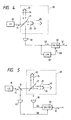
- Fig. 4 illustrates in block form an embodiment of the present invention.
- the parts corresponding to those in Fig. 1 are identified by the same reference numerals, and since the arrangement of the optical interferometer 20, which is an optical system for measuring the light 11 from the light source 10, is exactly the same as shown in Fig. 1, no description will be given of the optical interferometer 20.
- the optical interference signal SA from the photodetector 30 is branched to a low-pass filter 40, wherein a low-frequency component SB of the optical interference signal SA is extracted.
- the low-frequency component SB of the optical interference signal SA is a DC-like optical power signal SB of the light 11 containing a low-frequency variation component. That is, where the light source 10 is being excited by the commercial power line, a noise of 50 or 60 Hz, or 100 or 120 Hz gets mixed in the optical interference signal SA. Also in the case of DC lighting, a fluctuation in the DC power source voltage bring about a low-frequency optical power variation.
- the optical power signal SB containing this optical power variation as a noise component is extracted by the low-pass filter 40 and is applied to an arithmetic unit 50.
- the optical interference signal SA from the photodetector 30 is also provided to the arithmetic unit 50, wherein it is divided by the optical power signal SB, obtaining an optical interference signal SC with no noise component.
- coherency which represents interference light components at wavelengths except ⁇ 0 and varies with the distance of movement ⁇ l of the movable mirror 23.
- 2 ⁇ l/ ⁇ 0 is called a fringe frequency.
- the fluctuation component ⁇ I(t) modulates the amplitude of the optical interference signal as is evident from Expression (3), so that even if the frequency of the fluctuation component ⁇ I(t) (taken as f n ) is sufficiently lower than the fringe frequency f F , spectra of f F ⁇ f n and f F ⁇ 2f n , for example, appear as noise in the vicinity of the fringe frequency f F in the frequency band to be measured. Consequently, the waveform of the optical interference signal SA, which is actually detected by the photodetector 30, contains noise components as depicted in Fig. 3. In the embodiment shown in Fig.
- the output signal SC of the computing element 50 is free from the influence of the power fluctuation of the input light 11 as is evident from Expression (4), its waveform is substantially the same as that of the optical interference signal shown in Fig. 2 which is provided when the power of the input light 11 undergoes no fluctuation. Consequently, an accurate spectrum of the input light 11 can be obtained by a frequency analysis of the output signal SC of the arithmetic unit 50 through the fast Fourier transformation, for instance.
- the cut-off frequency of the low-pass filter 40 to be lower than the band of the fringe frequency corresponding to the spectrum measuring band, all noises attributable to fluctuation components lower than the above-mentioned cut-off frequency can be removed from the optical interference signal SA.
- the optical power signal SB corresponding to the power of the incident light 11 is extracted by the low-pass filter 40 from the optical interference signal SA which is the output of the photodetector 30, the power of the light 11 from the light source 10 may also be detected directly as the optical power signal SB.
- An embodiment therefor is depicted in Fig. 5, in which the light 11 emitted from the light source 10 is split by a half mirror 12 into light which passes through the half mirror 12 and is then incident to the optical interferometer 20 and light which is reflected by the half mirror 12 and is then incident to a second photodetector 41.
- the power signal SB corresponding to the power of the light 11 is detected by the second photodetector 41 and is provided to the arithmetic unit 50 for the division SA/SB.
- the other parts of this embodiment are the same as those in the Fig. 4 embodiment and no description will be given of them for the sake of simplicity.
- all noises attributable to fluctuation components in the entire frequency band contained in the light 11 can be removed from the optical interference signal SA.
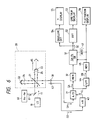
- Fig. 6 illustrates a modified form of the embodiment shown in Fig. 4.
- the optical interference signal SA is obtained at the output of the photodetector 30 as the movable mirror 23 of the optical interferometer 20 moves at a constant speed, but if the moving speed of the movable mirror 23 varies, the fringe frequency of the optical interference signal SA also fluctuates accordingly and no accurate results of spectrum analysis can be obtained.
- reference light which has a line spectrum of a stable wavelength, such as laser light, is applied to the optical interferometer 20, together with the light to be measured, and a reference optical interference signal is derived from reference interference light which is emitted from the optical interferometer 20.
- the optical interference signal of the light to be measured is sampled by a clock of the fringe frequency of the reference optical interference signal or a frequency N times higher than the fringe frequency, by which samples of the optical interference signal corresponding to the distance of movement of the movable mirror 23 are successively generated without being affected by the variation in the moving speed of the movable mirror 23.
- a reference light source 60 is provided in addition to the light source 10 and reference light 61 emitted from the reference light source 60 is applied to the optical interferometer 20, together with the light to be measured 11, as shown in Fig. 6.
- the reference light source 60 is one that is stable in wavelength and has a narrow spectrum characteristic, such as a He-Ne laser.
- the reference light 61 is also split to the fixed optical path 24 and the variable optical path 25 and both rays of light therefrom are combined by the half mirror 21 into reference interference light, which is received by a photodetector 42 for conversion into an electric signal.
- the amplitude of a reference optical interference signal SD which is provided from the photodetector 42 varies sinusoidally with a constant period, i.e. a constant fringe frequency, with respect to the distance of movement ⁇ l of the movable mirror 23.
- the reference optical interference signal SD has a peak for each fixed distance of movement of the movable mirror 23. Where the moving speed of the movable mirror 23 changes, the position of the peak also changes correspondingly on the time axis.
- the reference optical interference signal SD is provided to an N-multiplier 43, from which an N-multiplied signal is applied as a sampling clock CL to an A-D converter 31, wherein the level of the optical interference signal SA of the light to be measured 11 from the photodetector 30 is converted to a digital value for each sampling clock CL.
- the value of N of the N-multiplier 43 is selected such that the frequency of the sampling clock CL is more than twice higher than the fringe frequency of the optical interference signal SA.
- the sample data available from the A-D converter 31 is provided to a memory 32, in which sample data of one sweep of the movable mirror 23 is written in association with the sweep.
- the sample data from the A-D converter 31 is provided also to a digital low-pass filter 44, by which a low-frequency component containing the DC component and the fluctuation component of the power of the input light 11 is extracted as the optical power signal SB, and data about the optical power signal SB of one sweep of the movable mirror 23 is also written into a memory 45.
- the data SA and SB are read out of the memories 32 and 45 and provided to an arithmetic unit 51, wherein the division SA/SB described above with regard to Fig. 4 is performed to obtain the optical interference signal data SC from which the fluctuation component has been removed.
- the data SC thus obtained may be subjected to, for example, a spectrum analysis by an FFT analyzer 52, by which the spectrum of the input light 11 can be obtained.
- the optical interference signal SC obtained by the division SA/SB does not include the term of the power I B of the input light 11 as seen from Expression (4), and consequently, the spectral component obtained through frequency analysis of the result of the division SA/SB has been normalized by the power I B of the input light 11 and is unrelated to the power level of the input light 11. That is, if the spectrum distribution of the input light 11 remains unchanged, spectra of the same amplitudes are obtained irrespective of the magnitude of the power of the input light 11, and the results of analysis do not contain information about the power level of the input light 11.
- the arithmetic unit 51 multiplies the result of the division SA/SB by the power level P0 of the input light 11 as a coefficient so as to obtain a spectrum of an amplitude proportional to the power of the input light 11. Consequently, the output data SC of the arithmetic unit 51 assumes a value proportional to the power level P0 of the input light 11, and the amplitude of the spectrum obtained by the frequency analysis of the data SC becomes also proportional to the power level P0.
- the coefficient P0 that is used here is one of the data written in the memory 45, preferably, that data SB of a series of data stored in the memory 45 for one sweep which corresponds to the center position of the sweep.
- the movable mirror 23 of the optical interferometer 20 is moved for a distance from - ⁇ l to + ⁇ l in terms of the optical path difference between the fixed and movable optical paths 24 and 25, and the optical power data SB at an address corresponding to the vicinity of the position where the optical path difference is zero is read out of the memory 45 and is used as the coefficient P0.
- the optical power data SB in a predetermined number of periods before and after the position of zero optical path difference are read out of the memory 45 and averaged by an averager 47 indicated by the broken line in Fig. 6, and the resulting averager is used as the coefficient P0. In this instance, the coefficient P0 is less affected by the fluctuation component contained in the optical power.
- the computing element 51 outputs the optical interference signal SC from which the noise component has been removed.
- the optical spectrum of the light 11 to be measured can be displayed on a display 53.
- an envelope detector 54 is provided, by which a variation in the amplitude of the optical interference signal SC, that is, the coherency ⁇ in Expression (4), is detected.
- the coherency ⁇ By displaying the coherency ⁇ on a display 55 with the optical path difference ⁇ l represented on the abscissa, the coherency of the light 11 being measured can be displayed.
- fluctuations of the light 11 can be observed by displaying on a display 56 the optical power signal data SB read out of the memory 45.
- Fig. 7 illustrates another modification of the Fig. 4 embodiment, in which the method of employing the reference light 61 is applied to the Fig. 5 embodiment as is the case with the Fig. 6 embodiment.
- the parts corresponding to those in Figs. 5 and 6 are identified by the same reference numerals and characters.
- a portion of the light 11 emitted from the light source 10 is reflected by the half mirror 12 to the photodetector 41, wherein the power of the light 11 is converted to the electric signal SB, which is applied to an A-D converter 46.
- the A-D converter 46 converts the level of the optical power signal SB into a digital value upon each application thereto of the sampling clock CL derived by the N-multiplier 43 from the optical interference signal SD of the reference light 61.
- the output data of the A-D converter 46 is written into the memory 45 in association with the sweep of the movable mirror 23.
- an optical interference signal free from the fluctuation component can be obtained.
Landscapes
- Physics & Mathematics (AREA)
- Spectroscopy & Molecular Physics (AREA)
- General Physics & Mathematics (AREA)
- Spectrometry And Color Measurement (AREA)
- Instruments For Measurement Of Length By Optical Means (AREA)
Priority Applications (2)
| Application Number | Priority Date | Filing Date | Title |
|---|---|---|---|
| DE1990612083 DE69012083T2 (de) | 1990-01-08 | 1990-01-08 | Trennanordnung für optische Interferenzsignale. |
| EP19900100310 EP0436752B1 (de) | 1990-01-08 | 1990-01-08 | Trennanordnung für optische Interferenzsignale |
Applications Claiming Priority (1)
| Application Number | Priority Date | Filing Date | Title |
|---|---|---|---|
| EP19900100310 EP0436752B1 (de) | 1990-01-08 | 1990-01-08 | Trennanordnung für optische Interferenzsignale |
Publications (2)
| Publication Number | Publication Date |
|---|---|
| EP0436752A1 true EP0436752A1 (de) | 1991-07-17 |
| EP0436752B1 EP0436752B1 (de) | 1994-08-31 |
Family
ID=8203468
Family Applications (1)
| Application Number | Title | Priority Date | Filing Date |
|---|---|---|---|
| EP19900100310 Expired - Lifetime EP0436752B1 (de) | 1990-01-08 | 1990-01-08 | Trennanordnung für optische Interferenzsignale |
Country Status (2)
| Country | Link |
|---|---|
| EP (1) | EP0436752B1 (de) |
| DE (1) | DE69012083T2 (de) |
Cited By (4)
| Publication number | Priority date | Publication date | Assignee | Title |
|---|---|---|---|---|
| GB2280261A (en) * | 1993-06-30 | 1995-01-25 | Ando Electric | Optical wavemeter |
| RU2217710C1 (ru) * | 2002-05-13 | 2003-11-27 | Институт физики им. Л.В.Киренского СО РАН | Способ измерения корреляционной функции световых потоков и устройство для его осуществления |
| EP2515092A4 (de) * | 2009-12-14 | 2015-09-09 | Konica Minolta Holdings Inc | Interferometer und fourier-spektrometer damit |
| CN120651356A (zh) * | 2025-07-14 | 2025-09-16 | 上海拜安实业有限公司 | 一种干涉型光谱分析装置及分析方法 |
Citations (1)
| Publication number | Priority date | Publication date | Assignee | Title |
|---|---|---|---|---|
| FR2621753A1 (fr) * | 1987-10-13 | 1989-04-14 | Thomson Csf | Dispositif de commande automatique de gain et recepteur comportant un tel dispositif |
-
1990
- 1990-01-08 EP EP19900100310 patent/EP0436752B1/de not_active Expired - Lifetime
- 1990-01-08 DE DE1990612083 patent/DE69012083T2/de not_active Expired - Fee Related
Patent Citations (1)
| Publication number | Priority date | Publication date | Assignee | Title |
|---|---|---|---|---|
| FR2621753A1 (fr) * | 1987-10-13 | 1989-04-14 | Thomson Csf | Dispositif de commande automatique de gain et recepteur comportant un tel dispositif |
Non-Patent Citations (4)
| Title |
|---|
| APPLIED OPTICS, vol. 13, no. 4, April 1974, pages 723-725; R.J. DOUGLAS et al.: "Simple double-beam modification for far infrared interferometers" * |
| IBM TECHNICAL DISCLOSURE BULLETIN, vol. 17, no. 7, December 1974, pages 1927-1928, New York, US; F. BUCKLEY, III: "Automatic gain control system" * |
| J.E.E. JOURNAL OF ELECTRONIC ENGINEERING, vol. 23, no. 236, August 1986, pages 58-60; N. ARAKAWA: "Optical spectrum analyer: New techniques and new functions" * |
| REVIEW OF SCIENTIFIC INSTRUMENTS, vol. 59, no. 2, February 1988, pages 242-248, New York, US; F. OZANAM et al.: "Fourier transform, electromodulated, infrared spectrometer for studies at the electrochemical interface" * |
Cited By (7)
| Publication number | Priority date | Publication date | Assignee | Title |
|---|---|---|---|---|
| GB2280261A (en) * | 1993-06-30 | 1995-01-25 | Ando Electric | Optical wavemeter |
| FR2708344A1 (fr) * | 1993-06-30 | 1995-02-03 | Ando Electric | Ondemètre optique. |
| GB2280261B (en) * | 1993-06-30 | 1997-05-21 | Ando Electric | Optical wavemeter |
| RU2217710C1 (ru) * | 2002-05-13 | 2003-11-27 | Институт физики им. Л.В.Киренского СО РАН | Способ измерения корреляционной функции световых потоков и устройство для его осуществления |
| EP2515092A4 (de) * | 2009-12-14 | 2015-09-09 | Konica Minolta Holdings Inc | Interferometer und fourier-spektrometer damit |
| CN120651356A (zh) * | 2025-07-14 | 2025-09-16 | 上海拜安实业有限公司 | 一种干涉型光谱分析装置及分析方法 |
| CN120651356B (zh) * | 2025-07-14 | 2026-04-21 | 上海拜安实业有限公司 | 一种干涉型光谱分析装置及分析方法 |
Also Published As
| Publication number | Publication date |
|---|---|
| DE69012083D1 (de) | 1994-10-06 |
| DE69012083T2 (de) | 1995-01-26 |
| EP0436752B1 (de) | 1994-08-31 |
Similar Documents
| Publication | Publication Date | Title |
|---|---|---|
| US5110211A (en) | Optical interference signal extractor with device for reduced noise from optical light power variation | |
| EP0193742B1 (de) | Interferometrie mit veränderlicher Wellenlänge und Interferometer mit Laserdiode | |
| US6351309B1 (en) | Dual modulation laser line-locking technique for wavelength modulation spectroscopy | |
| GB1510827A (en) | Method of and apparatus for analyzing light | |
| US4225233A (en) | Rapid scan spectrophotometer | |
| US4549806A (en) | Method and apparatus measuring absolute rotation | |
| US5153667A (en) | Apparatus for detecting the change of light intensity | |
| US3286582A (en) | Interference technique and apparatus for spectrum analysis | |
| JPH06148072A (ja) | ガス濃度測定方法およびその測定装置 | |
| EP0436752A1 (de) | Trennanordnung für optische Interferenzsignale | |
| KR930016765A (ko) | 광 검출기의 진폭 선형성 | |
| US20190277699A1 (en) | Interference spectrophotometer and two-beam interferometer | |
| US5039222A (en) | Apparatus and method for producing fourier transform spectra for a test object in fourier transform spectrographs | |
| JP2784468B2 (ja) | 光干渉信号抽出装置 | |
| JPS6140928B2 (de) | ||
| CN115655663B (zh) | 全光纤结构激光器的线宽测量方法及系统 | |
| JP2714644B2 (ja) | 光スペクトラムアナライザ | |
| JP2889248B2 (ja) | 光スペクトラムアナライザ用光干渉計 | |
| JPS60202329A (ja) | 波長可変レーザを用いた吸収分光分析装置 | |
| JPH08101232A (ja) | 電圧測定装置 | |
| EP0737843A2 (de) | Kohärenzbeobachtungsverfahren und Apparat unter Anwendung von Interfenenzrausch | |
| US3619063A (en) | Spectrometer for the far infrared | |
| USRE27947E (en) | Interference technique and apparatus for spectrum analysis | |
| JPH06347507A (ja) | 半導体レーザの選別法 | |
| SU1732291A1 (ru) | Способ определени фазовой скорости поверхностной электромагнитной волны |
Legal Events
| Date | Code | Title | Description |
|---|---|---|---|
| PUAI | Public reference made under article 153(3) epc to a published international application that has entered the european phase |
Free format text: ORIGINAL CODE: 0009012 |
|
| 17P | Request for examination filed |
Effective date: 19900108 |
|
| AK | Designated contracting states |
Kind code of ref document: A1 Designated state(s): DE FR GB IT NL |
|
| 17Q | First examination report despatched |
Effective date: 19930318 |
|
| GRAA | (expected) grant |
Free format text: ORIGINAL CODE: 0009210 |
|
| AK | Designated contracting states |
Kind code of ref document: B1 Designated state(s): DE |
|
| REF | Corresponds to: |
Ref document number: 69012083 Country of ref document: DE Date of ref document: 19941006 |
|
| EN | Fr: translation not filed | ||
| PLBE | No opposition filed within time limit |
Free format text: ORIGINAL CODE: 0009261 |
|
| STAA | Information on the status of an ep patent application or granted ep patent |
Free format text: STATUS: NO OPPOSITION FILED WITHIN TIME LIMIT |
|
| 26N | No opposition filed | ||
| PGFP | Annual fee paid to national office [announced via postgrant information from national office to epo] |
Ref country code: DE Payment date: 20080104 Year of fee payment: 19 |
|
| PG25 | Lapsed in a contracting state [announced via postgrant information from national office to epo] |
Ref country code: DE Free format text: LAPSE BECAUSE OF NON-PAYMENT OF DUE FEES Effective date: 20090801 |