EP0737843A2 - Kohärenzbeobachtungsverfahren und Apparat unter Anwendung von Interfenenzrausch - Google Patents
Kohärenzbeobachtungsverfahren und Apparat unter Anwendung von Interfenenzrausch Download PDFInfo
- Publication number
- EP0737843A2 EP0737843A2 EP96302444A EP96302444A EP0737843A2 EP 0737843 A2 EP0737843 A2 EP 0737843A2 EP 96302444 A EP96302444 A EP 96302444A EP 96302444 A EP96302444 A EP 96302444A EP 0737843 A2 EP0737843 A2 EP 0737843A2
- Authority
- EP
- European Patent Office
- Prior art keywords
- arms
- energy
- source
- delay
- energy source
- Prior art date
- Legal status (The legal status is an assumption and is not a legal conclusion. Google has not performed a legal analysis and makes no representation as to the accuracy of the status listed.)
- Withdrawn
Links
- 238000000034 method Methods 0.000 title claims abstract description 24
- 238000005259 measurement Methods 0.000 claims abstract description 23
- 238000001228 spectrum Methods 0.000 claims description 9
- 230000001427 coherent effect Effects 0.000 claims description 3
- 230000001934 delay Effects 0.000 claims description 3
- 230000007613 environmental effect Effects 0.000 claims description 2
- 239000000126 substance Substances 0.000 claims 2
- 230000003287 optical effect Effects 0.000 description 11
- 238000010586 diagram Methods 0.000 description 9
- 230000005284 excitation Effects 0.000 description 3
- 230000005281 excited state Effects 0.000 description 3
- 230000010355 oscillation Effects 0.000 description 3
- ZLMJMSJWJFRBEC-UHFFFAOYSA-N Potassium Chemical compound [K] ZLMJMSJWJFRBEC-UHFFFAOYSA-N 0.000 description 2
- 238000005311 autocorrelation function Methods 0.000 description 2
- 230000001066 destructive effect Effects 0.000 description 2
- 238000000295 emission spectrum Methods 0.000 description 2
- 230000002452 interceptive effect Effects 0.000 description 2
- 238000005305 interferometry Methods 0.000 description 2
- 229910052700 potassium Inorganic materials 0.000 description 2
- 239000011591 potassium Substances 0.000 description 2
- 238000001237 Raman spectrum Methods 0.000 description 1
- 238000010521 absorption reaction Methods 0.000 description 1
- 238000000862 absorption spectrum Methods 0.000 description 1
- 238000007796 conventional method Methods 0.000 description 1
- 230000003247 decreasing effect Effects 0.000 description 1
- 230000003111 delayed effect Effects 0.000 description 1
- 238000013461 design Methods 0.000 description 1
- 238000001514 detection method Methods 0.000 description 1
- 230000000694 effects Effects 0.000 description 1
- 230000005283 ground state Effects 0.000 description 1
- 239000000463 material Substances 0.000 description 1
- 230000035945 sensitivity Effects 0.000 description 1
- 238000000926 separation method Methods 0.000 description 1
- 238000013519 translation Methods 0.000 description 1
Images


Classifications
-
- G—PHYSICS
- G01—MEASURING; TESTING
- G01J—MEASUREMENT OF INTENSITY, VELOCITY, SPECTRAL CONTENT, POLARISATION, PHASE OR PULSE CHARACTERISTICS OF INFRARED, VISIBLE OR ULTRAVIOLET LIGHT; COLORIMETRY; RADIATION PYROMETRY
- G01J9/00—Measuring optical phase difference; Determining degree of coherence; Measuring optical wavelength
- G01J9/02—Measuring optical phase difference; Determining degree of coherence; Measuring optical wavelength by interferometric methods
Definitions
- the present invention relates to a method and apparatus for performing interference measurements by observation of interference noise, or generally, Coherence Observation by Interference Noise (hereinafter, "COIN"). It further relates to the use of COIN for the measurement of light source autocorrelation and for the measurement of spectra.
- COIN Coherence Observation by Interference Noise
- Interference is a well-documented phenomenon in physical optics and interferometry, based on interference, has many practical applications such as the precise measurement or comparison of wavelengths, the measurement of very small distances of translation, or thicknesses, the detection of disturbances or inhomogeneities in optical media, the determination of refractive indices of materials, etc.
- a conventional interferometer such as the Michelson interferometer
- a light beam is split into two, and the two beams are made to traverse optical paths of different lengths before being recombined into a single output beam or onto a detector.
- the interference pattern is observed as a function of the optical path difference between the two arms, providing information about the mechanism producing the optical path difference.
- conventional interferometry is extremely accurate and sensitive, it is this very sensitivity to the stability (or rather, the lack thereof) of the relative phases of the two beams which imposes on any interferometric apparatus demands of rigidity and general mechanical perfection of such stringency that one tends to avoid interferometric measurements whenever possible.
- the above object is achieved by providing a method for performing interference measurements by observation of interference noise, comprising the steps of splitting an energy beam from an energy source into two beams directed into two different arms of an interferometer; using variable delay-generating means to introduce a path difference between said two arms; introducing a variable phase difference between said two arms, and recombining said two energy beams into a single beam.
- the invention further provides an apparatus for performing interference measurements by observation of interference noise, comprising a beam splitter in which an energy beam from an energy source is split into two arms; a variable delay unit in which a variable delay is imposed on one of said two arms; a constant delay unit imposing a constant delay on the other one of said two arms; a recombiner in which said two arms are recombined to form a single output beam; characterized in that a phase randomizer is interposed between said constant delay unit or said variable delay unit and said recombiner to introduce a variable optical phase difference between said two arms.
- Fig. 1 a schematic block diagram of a conventional interferometer, in which a beam 2 from a light source S is split by a beam splitter 4 into two arms 6, 6', one of which, 6, reaches a recombiner 8 via a variable delay unit 10; the other, 6', is led to the recombiner 8 via a constant delay unit 12.
- the two arms 6, 6' are superposed, producing an output interference signal 14, the intensity of which is measured at the detector 16 as a function of the relative phases between the arms and, if one arm is of a fixed length, as a function of the optical path length difference of the variable arm.
- the signal is then analyzed in an analyzer 18.
- the COIN interferometer i.e., the interferometer based on the COIN method, differs from the conventional interferometer in that a new element, a "phase randomizer" 20 has been added to one arm of the split beam, providing a random phase (between 0 and 2 ⁇ ), as can be seen in Fig. 2 (which is actually a block diagram representing a first embodiment of the invention, with elements having similar functions to those shown in Fig. 1 carrying the same reference numerals).
- the measured quantity is not the intensity of the interference signal, but rather the fluctuations in the intensity. These fluctuations are statistically analyzed, namely, a statistical measure of the noise (e.g., the variance) is derived, which is related to the interference fringe contrast for any given optical path difference between the two arms.
- the random phase is produced either by a dedicated unit, or by controlled or uncontrolled environmental fluctuations originating within or outside of the interferometer itself, or by one or more components of the system, other than a dedicated phase randomizer.
- phase randomizer 20 is seen to be interposed between the constant delay unit 12 and the recombiner 8, it could equally well be interposed between the latter and the variable delay unit 10.
- the COIN method may be used for characterizing the light itself, or may be used for characterizing a medium with which the light is interacting.
- the COIN method is used for the determination of the source autocorrelation, while in the second case, the method is used for measuring medium spectra, such as emission, absorption, or Raman spectra.
- the standard tool for autocorrelation measurements is a Michelson interferometer, where, as already mentioned, an incoming beam of light is split in two parts by a beamsplitter, the two parts being recombined after traversing different optical paths, and the resulting output interference signal being measured by a detector.
- Optical path difference is translated directly into time delay between the two recombined beams.
- the resulting interference signal will have fast oscillations at the optical frequency period, with an envelope that is the autocorrelation of the input pulse amplitude envelope function.
- the additional random relative phase will cause the disapppearance of the fast oscillations, converting them to intensity fluctuations.
- the average of the output signal will be constant, but the magnitude of its fluctuations will depend on the modulation depth at any given time delay, i.e., the difference in intensity between the nearest constructive interference peak and destructive interference trough, revealing the envelope function of the interference fringes.
- the modulation depth of the interference can be measured.
- the information obtained in this way is the square of the envelope autocorrelation function (with the autocorrelation function of any function describing the general dependence of the values of the data at one time on the values of these data at another time).
- Fig. 3 illustrates the result of a measurement of the autocorrelation of a short laser pulse by the arrangement of Fig. 2.
- the diagram shows the variance as a function of delay.
- the autocorrelation measurement may be performed on a two-color light source, where one color is the unknown light and the other is light from a source of known wavelength (e.g., a HeNe laser), internal or external to the measurement device. From the interference pattern of the two-color source, the wavelength of the unknown source may be extracted.
- a source of known wavelength e.g., a HeNe laser
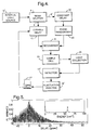
- Fig. 4 shows the block diagram of a COIN interferometer as used as a spectrometer. The differences with respect to the block diagram of Fig. 2 are obvious and self-explanatory.
- the light source S' is part of the instrument, with the recombined beam being led into a sample cell 24, and the fluorescence generated therein being collected by a light collector 26, from which the light reaches the detector 16'.
- the light sources S and S' can be a pulsed or continuous laser, an incandescent bulb or other incoherent source, or light originating in several independent light sources (coherent or incoherent).
- COIN spectrometers are based on the introduction of a random relative phase between the pair of excitation pulses, and the observation of the total fluorescence, or of the transmitted signal intensity through the sample, after each event, where an event is the excitation by one or more pairs of pulses of the same relative phase at a given delay. While in the following example fluorescence will be referred to, this term should be understood in a more general context of fluorescence or absorption as measured by the transmitted energy. At zero delay, the interference may be either fully constructive, or fully destructive, or anything in between, causing large intensity fluctuations of the fluorescence. For two identical input pulses, the emitted energy will fluctuate between zero and four times the emission produced by a single pulse.
- the second pulse encounters an atom (molecule) whose coherence is modified both by the internal dynamics and by coherent dephasing processes. As long as the atom maintains its coherence, the total population of the excited state is still affected by the quantum interference. The total fluorescence intensity will fluctuate having a noise level that depends upon the delay.
- This gradually decreasing interference noise provides the same time-resolved information as in the case where the phases of the two pulses are locked together but, as already mentioned, measurement using the COIN system does not pose the severe demands concerning rigidity of the mechanical structure of the instrument and protection against thermal effects.
- Fig. 5 depicts the exponentially decaying oscillations of the measured fluorescence variance, with the inset showing the absolute value of the Fourier transform of the data points.
- the peak corresponds to the energy splitting of the potassium doublet (57.7 cm -1 ), the two small side-bands being artifacts due to the 1 mm pitch of the mechanical lead-screw used in the motorized delay line).
- the method according to the invention is suitable for other waves capable of interfering with each other, such as quantum probabilities of atomic or molecular excitations, electromagnetic waves, acoustic waves or transverse or longitudinal waves.
Landscapes
- Physics & Mathematics (AREA)
- Spectroscopy & Molecular Physics (AREA)
- General Physics & Mathematics (AREA)
- Investigating, Analyzing Materials By Fluorescence Or Luminescence (AREA)
- Instruments For Measurement Of Length By Optical Means (AREA)
- Length Measuring Devices By Optical Means (AREA)
Applications Claiming Priority (2)
| Application Number | Priority Date | Filing Date | Title |
|---|---|---|---|
| IL11331195 | 1995-04-10 | ||
| IL113311A IL113311A (en) | 1995-04-10 | 1995-04-10 | Method and apparatus for coherence observation by interference noise |
Publications (2)
| Publication Number | Publication Date |
|---|---|
| EP0737843A2 true EP0737843A2 (de) | 1996-10-16 |
| EP0737843A3 EP0737843A3 (de) | 1997-04-09 |
Family
ID=11067342
Family Applications (1)
| Application Number | Title | Priority Date | Filing Date |
|---|---|---|---|
| EP96302444A Withdrawn EP0737843A3 (de) | 1995-04-10 | 1996-04-04 | Kohärenzbeobachtungsverfahren und Apparat unter Anwendung von Interfenenzrausch |
Country Status (4)
| Country | Link |
|---|---|
| US (1) | US5805282A (de) |
| EP (1) | EP0737843A3 (de) |
| JP (1) | JPH0989517A (de) |
| IL (1) | IL113311A (de) |
Cited By (1)
| Publication number | Priority date | Publication date | Assignee | Title |
|---|---|---|---|---|
| US6592039B1 (en) | 2000-08-23 | 2003-07-15 | International Business Machines Corporation | Digital pen using interferometry for relative and absolute pen position |
Families Citing this family (2)
| Publication number | Priority date | Publication date | Assignee | Title |
|---|---|---|---|---|
| US7675020B2 (en) * | 2006-08-28 | 2010-03-09 | Avago Technologies General Ip (Singapore) Pte. Ltd. | Input apparatus and methods having diffuse and specular tracking modes |
| WO2014055749A1 (en) * | 2012-10-04 | 2014-04-10 | Zygo Corporation | Position monitoring system with reduced noise |
Citations (1)
| Publication number | Priority date | Publication date | Assignee | Title |
|---|---|---|---|---|
| US5305333A (en) * | 1992-12-31 | 1994-04-19 | North American Philips Corporation | Method and apparatus for amplitude modulation of laser light |
Family Cites Families (5)
| Publication number | Priority date | Publication date | Assignee | Title |
|---|---|---|---|---|
| DE3371559D1 (en) * | 1982-10-08 | 1987-06-19 | Nat Res Dev | Irradiative probe system |
| US5191614A (en) * | 1988-11-14 | 1993-03-02 | Mcdonnell Douglas Corporation | Secure communication system |
| US5321501A (en) * | 1991-04-29 | 1994-06-14 | Massachusetts Institute Of Technology | Method and apparatus for optical imaging with means for controlling the longitudinal range of the sample |
| US5131748A (en) * | 1991-06-10 | 1992-07-21 | Monchalin Jean Pierre | Broadband optical detection of transient motion from a scattering surface by two-wave mixing in a photorefractive crystal |
| US5589936A (en) * | 1992-09-14 | 1996-12-31 | Nikon Corporation | Optical measuring apparatus for measuring physichemical properties |
-
1995
- 1995-04-10 IL IL113311A patent/IL113311A/xx not_active IP Right Cessation
-
1996
- 1996-04-04 EP EP96302444A patent/EP0737843A3/de not_active Withdrawn
- 1996-04-08 US US08/629,074 patent/US5805282A/en not_active Expired - Fee Related
- 1996-04-10 JP JP8087849A patent/JPH0989517A/ja active Pending
Patent Citations (1)
| Publication number | Priority date | Publication date | Assignee | Title |
|---|---|---|---|---|
| US5305333A (en) * | 1992-12-31 | 1994-04-19 | North American Philips Corporation | Method and apparatus for amplitude modulation of laser light |
Cited By (1)
| Publication number | Priority date | Publication date | Assignee | Title |
|---|---|---|---|---|
| US6592039B1 (en) | 2000-08-23 | 2003-07-15 | International Business Machines Corporation | Digital pen using interferometry for relative and absolute pen position |
Also Published As
| Publication number | Publication date |
|---|---|
| JPH0989517A (ja) | 1997-04-04 |
| EP0737843A3 (de) | 1997-04-09 |
| IL113311A0 (en) | 1995-07-31 |
| US5805282A (en) | 1998-09-08 |
| IL113311A (en) | 1997-07-13 |
Similar Documents
| Publication | Publication Date | Title |
|---|---|---|
| KR100328007B1 (ko) | 다중패스 간섭법을 사용하여 공기의 굴절률을 측정하는 슈퍼헤테 로다인 방법 및 장치 | |
| US8693004B2 (en) | Dual-etalon cavity ring-down frequency-comb spectroscopy with broad band light source | |
| KR0163627B1 (ko) | 광열변위계측에 의한 시료평가방법 | |
| US5359410A (en) | Complete diagnostics of ultrashort pulses without nonlinear process | |
| KR20000068090A (ko) | 슈퍼헤테로다인 간섭계 및 전자 주파수 증배를 사용하여 공기의굴절률을 보상하기 위한 방법 | |
| US5110211A (en) | Optical interference signal extractor with device for reduced noise from optical light power variation | |
| CN110207733B (zh) | 基于扫频激光的光纤干涉仪臂长差测量装置及方法 | |
| US3885874A (en) | Laser plasma diagnostic using ring resonators | |
| US5805282A (en) | Method and apparatus for coherence observation by interference noise | |
| JP3029757B2 (ja) | 光熱変位計測による試料評価方法 | |
| Trolinger | Ultrahigh resolution interferometry | |
| Junttila et al. | Fourier transform wavemeter | |
| CN112197878A (zh) | 基于光频域反射仪的高精度光波长检测方法及系统 | |
| WO2018005987A1 (en) | Systems and methods for interrogating parameters at a plurality of locations in a sample | |
| JP2728773B2 (ja) | 半導体多層薄膜の膜厚評価装置及び膜厚評価方法 | |
| JP4002163B2 (ja) | パルス間位相差測定方法および装置 | |
| KR0168444B1 (ko) | 열팽창진동을 이용한 시료평가방법 | |
| JP3040140B2 (ja) | 色収差測定方法及び測定装置 | |
| EP0436752A1 (de) | Trennanordnung für optische Interferenzsignale | |
| CN119316046B (zh) | 基于参考光纤相位补偿的光时域反射系统及解调方法 | |
| JP2006220600A (ja) | 光熱変換測定装置及びその方法 | |
| Mori et al. | Interferometric Method for Measuring Ultrasonic Light Diffraction Spectra | |
| RU2045004C1 (ru) | Способ измерения временных корреляционных функций флуктуаций отражательной и/или поглощательной способностей исследуемых объектов и устройство для его осуществления | |
| SU877444A1 (ru) | Способ измерени виброускорений и устройство дл его осуществлени | |
| JPH05288721A (ja) | 光熱変位計測による試料評価方法 |
Legal Events
| Date | Code | Title | Description |
|---|---|---|---|
| PUAI | Public reference made under article 153(3) epc to a published international application that has entered the european phase |
Free format text: ORIGINAL CODE: 0009012 |
|
| AK | Designated contracting states |
Kind code of ref document: A2 Designated state(s): DE FR GB IT |
|
| PUAL | Search report despatched |
Free format text: ORIGINAL CODE: 0009013 |
|
| AK | Designated contracting states |
Kind code of ref document: A3 Designated state(s): DE FR GB IT |
|
| 17P | Request for examination filed |
Effective date: 19970920 |
|
| 17Q | First examination report despatched |
Effective date: 20000426 |
|
| GRAG | Despatch of communication of intention to grant |
Free format text: ORIGINAL CODE: EPIDOS AGRA |
|
| GRAG | Despatch of communication of intention to grant |
Free format text: ORIGINAL CODE: EPIDOS AGRA |
|
| GRAH | Despatch of communication of intention to grant a patent |
Free format text: ORIGINAL CODE: EPIDOS IGRA |
|
| STAA | Information on the status of an ep patent application or granted ep patent |
Free format text: STATUS: THE APPLICATION IS DEEMED TO BE WITHDRAWN |
|
| 18D | Application deemed to be withdrawn |
Effective date: 20020723 |