EP0436767A2 - Cassette à film - Google Patents
Cassette à film Download PDFInfo
- Publication number
- EP0436767A2 EP0436767A2 EP90100655A EP90100655A EP0436767A2 EP 0436767 A2 EP0436767 A2 EP 0436767A2 EP 90100655 A EP90100655 A EP 90100655A EP 90100655 A EP90100655 A EP 90100655A EP 0436767 A2 EP0436767 A2 EP 0436767A2
- Authority
- EP
- European Patent Office
- Prior art keywords
- film
- cassette
- spool
- cassette body
- leader
- Prior art date
- Legal status (The legal status is an assumption and is not a legal conclusion. Google has not performed a legal analysis and makes no representation as to the accuracy of the status listed.)
- Withdrawn
Links
Images






Classifications
-
- G—PHYSICS
- G03—PHOTOGRAPHY; CINEMATOGRAPHY; ANALOGOUS TECHNIQUES USING WAVES OTHER THAN OPTICAL WAVES; ELECTROGRAPHY; HOLOGRAPHY
- G03B—APPARATUS OR ARRANGEMENTS FOR TAKING PHOTOGRAPHS OR FOR PROJECTING OR VIEWING THEM; APPARATUS OR ARRANGEMENTS EMPLOYING ANALOGOUS TECHNIQUES USING WAVES OTHER THAN OPTICAL WAVES; ACCESSORIES THEREFOR
- G03B17/00—Details of cameras or camera bodies; Accessories therefor
- G03B17/28—Locating light-sensitive material within camera
- G03B17/30—Locating spools or other rotatable holders of coiled film
-
- G—PHYSICS
- G03—PHOTOGRAPHY; CINEMATOGRAPHY; ANALOGOUS TECHNIQUES USING WAVES OTHER THAN OPTICAL WAVES; ELECTROGRAPHY; HOLOGRAPHY
- G03B—APPARATUS OR ARRANGEMENTS FOR TAKING PHOTOGRAPHS OR FOR PROJECTING OR VIEWING THEM; APPARATUS OR ARRANGEMENTS EMPLOYING ANALOGOUS TECHNIQUES USING WAVES OTHER THAN OPTICAL WAVES; ACCESSORIES THEREFOR
- G03B2217/00—Details of cameras or camera bodies; Accessories therefor
- G03B2217/26—Holders for containing light-sensitive material and adapted to be inserted within the camera
- G03B2217/261—Details of spools
-
- G—PHYSICS
- G03—PHOTOGRAPHY; CINEMATOGRAPHY; ANALOGOUS TECHNIQUES USING WAVES OTHER THAN OPTICAL WAVES; ELECTROGRAPHY; HOLOGRAPHY
- G03B—APPARATUS OR ARRANGEMENTS FOR TAKING PHOTOGRAPHS OR FOR PROJECTING OR VIEWING THEM; APPARATUS OR ARRANGEMENTS EMPLOYING ANALOGOUS TECHNIQUES USING WAVES OTHER THAN OPTICAL WAVES; ACCESSORIES THEREFOR
- G03B2217/00—Details of cameras or camera bodies; Accessories therefor
- G03B2217/26—Holders for containing light-sensitive material and adapted to be inserted within the camera
- G03B2217/266—Thrust-type cartridges
Definitions
- This invention relates to a film cassette containing a photographic roll film light-tight and more particularly to a film cassette in which a film leader of a film roll is fed by rotating a spool having a roll film wound on it.
- a film cassette containing a roll of 35mm photographic film strip in width is used as shown in Fig. 34.
- This 35mm type of a film cassette is designed as such that the film strip with one end thereof retained by a spool 1 made of a resin material is wound on the spool 1, the spool 1 having this roll film is rotatably contained in a metallic cassette shell or cassette body 3 and the film leader 2 of the roll film is protruded from a film withdrawing mouth 3a beforehand.
- USP4832275, USP4834306 and USP4846418 propose film cassettes in which the film leader is also taken up and kept within the cassette when the film is unused yet and the film cassette containing the film upto the film leader can be put into a camera in that state.
- These film cassette are designed such that the spool disposed within the cassette is rotated by a mechanism on the side of a camera in order to feed the film leader. As the film leader is not protruded from the cassette at all, it has such a significant advantage as that the operation for loading the film cassette into the camera is easy.
- the plush In order to smoothly feed the film leader from the film withdrawing mouth without fail by rotating the spool, it is necessary to reduce the resister applied to the film strip at the time when the film is being fed. It is also required, as in the conventional film cassette, that a shading structure is provided so that outside light does not enter into the cassette from the film withdrawing mouth. If the plush is used, as seen in the prior art, in order to meet with this requirement, the resister applied to the film leader at the time when the film is being fed becomes large. As a result, there is a fear that the film leader is bent in the middle of feeding the film and a jamming is taken place disenabling the feeding of the film. Particularly, in case light is to be shaded merely by providing the plush to the film withdrawing mouth, the plush must have a high density of distribution of pile yarns and therefore the resister applied to the film leader is much increased.
- a main object of the present invention is to provide a film cassette in which the film leader can be smoothly and surely fed from the cassette by rotating a spool having a film roll wound on it.
- Another object of the present invention is to provide a film cassette in which the film withdrawing mouth of the cassette is provided with shading means so that a large load is not incurred to the film leader when the film is being fed caused by rotation of the spool.
- a further object of the present invention is to provide a film cassette in which the friction resister between the outermost peripheral surface of the film roll and the inner wall of the cassette is reduced when the film roll is rotated within the cassette together with the spool.
- the film withdrawing mouth formed in the cassette body is closed with shading means which is designed such that the film leader can be smoothly withdrawn from the mouth.
- shading means there may be employed an open- and closeable cover member, flexible shading piece, and an arcuate passage.
- the cover member In case the cover member is employed, the cover member is moved to an open position by a mechanism on the side of the camera after the film cassette is put into the film feeding chamber and the back cover member of the camera is closed.
- the spool rotatably contained in the cassette body has a film roll wound thereon, and the terminal of the film is fixed to the film.
- the film roll When the spool is rotated by the mechanism on the side of the camera, the film roll is rotated within the cassette body together with the spool.
- the film leader of the film roll is fed outside the cassette body through the film withdrawing mouth appeared after the cover member is retreated. Since the shading of the film withdrawing mouth can be achieved by closing the cover member, it is not necessary to provide a shading plush to the film withdrawing mouth and the film leader can be smoothly fed from the film withdrawing mouth.
- the film leader is fed from the film withdrawing mouth through this film passage when the spool is rotated.
- the curved passage portion is served not only as a guide for feeding the film leader but also as means for damping the light entered from the film withdrawing mouth so as to prevent the outside light from directly reaching the film roll set in the cassette body.
- a reflection reducing treatment is applied to the inner surface of the film passage.
- a flexible shading piece is attached to or in the vicinity of the film withdrawing mouth. As the shading piece is readily deformed by the film leader when the film leaded is fed, an excessive resistance is not applied to the film leader and a smooth movement of the film leader is assured.
- the friction resistance between the inner wall of the cassette body and the film roll is made as small as possible.
- the cassette body and the spool are formed of a molded product of resin which contains a shading substance and an activator is applied to the cassette body.
- a camera using this film cassette requires a mechanism for catching and withdrawing the film leader from the cassette as the conventional sprocket mechanism or the like, and therefore the structure of the camera becomes simple. Further, even if the film is completely taken up within the cassette up to the film leader after a photograph is taken, the favorable shading ability can be maintained and the film strip can be feed simply by rotating the spool at the time when the film is developed. Accordingly, it does not take much time and labor for disassembling the camera in order to taken out an exposed film roll which is wound on the spool and a preliminary processing becomes easy at the time when the film is developed.
- a film cassette 9 comprises a cassette 10 and a film roll 12 contained in the cassette 10.
- the cassette 10 comprises a generally rectangular parallelopiped cassette body 15, a cover member 14, and a spool 11.
- a cylindrical pocket-like storing portion 13 for storing the spool 11 having the film roll 12 wound thereon is formed in the cassette body 15, and the cover member 15 is mounted on the cassette body 15 as such that the cover member 15 can be opened and closed.
- the cover member 14 is attached at one side thereof to cassette body 15 by supersonic welding. In the illustrated example of Fig. 2, the cassette body 15 is shown in a state where the cover member 14 is removed from the cassette body 15.
- the cassette body 15 is provided on its upper surface with a rectangular opening 13a, and an eaves-like projecting portion 16 is integrally formed with the upper surface of the cassette body 15 in such a manner as to protrude from one side thereof.
- the eaves-like projecting portion 16 is provided on its upper surface with a retaining projecting member 17 which, as shown in Fig. 9, is engaged in a retaining hole 39 formed in a film leader 120a in order to prevent the film leader 120a from entering into the cylindrical pocket-like storing portion 13.
- the eaves-like projecting portion 16 is also provided with a groove 21 formed on the side of its root. Furthermore, A step 20 is formed on the other three sides surrounding the opening 15a.
- the cassette body 15 has an opening 19 formed in one side surface 22 thereof and adapted to rotatably receive a driving boss 18 of the spool 11. Furthermore, the cassette body 15 is provided on both side surfaces 22 and 23 thereof with thin cutout portions 24 and 25 such that the cutout portions 24 and 25 are located at both sides of the eaves-like projecting portion 16, and projecting members 26 and 27 are projected from the cutout portions 24 and 25.
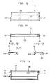
- the bottom surface of the cover member 14, as shown in Figs. 10 through 14, is provided with the retaining projecting member 17 formed on the cassette body 15, and with a recess portion 28 and a rib 29 which are formed in position corresponding to the retaining projecting member 17 and the groove 21.
- the cover member 14 includes lugs 30 and 31 projecting on the side of its lower surface in such a manner as to correspond to the cutouts 24 and 25 which are formed in the both side surfaces 22 and 23 of the cassette body 15.
- holes 32 and 33 are formed in the lugs 30 and 31 at position corresponding to the projecting members 26 and 27.
- the spool 11, as shown in Figs. 3 through 5, has a driving boss 18 which is to be inserted into an opening 19 of the cassette body 15 on its one end side.
- flanges 34 and 35 are integrally formed in such a manner as to keep slightly wider space than the width of the film roll 12.
- An annular thin portion 36 is formed on the end face of the flange 35.
- the annular thin portion 36 has a smaller diameter than that of an annular projecting member 37 which is formed on the inner wall of one side surface of the cassette body 15.
- the film strip 120 is 35mm in width and is provided with known perforations 120b along both side edges thereof. Further, the terminal end portion of the film strip 120 is provided with a retaining hole 38 which is to be retained by the spool 11, and the film leader 120a is provided with a retaining hole 39 which is to be caught by the retaining projecting member 17. This film strip 120 is wound on the spool 14 to form the film roll 12.
- the spool having the film roll 12 wound thereon is put into the cassette body 15 first.
- the flange 34 is located in the inner position of the opening 19, light entered between the opening 19 and the driving boss 18 is shaded by the flange 34.
- the retaining hole 39 of the film leader 120a is engaged with the retaining projecting member 17 formed on the eaves-like projecting member 16 of the cassette body 15.
- the cover member 14 is put on the cassette body 15 so that it covers the opening 13a.
- the piece 40 is integral with the rear end side of the cover member 14, and the piece 40 is held in alignment with the inner side of the step 20.
- a supersonic horn is urged against the cassette body 15 from outside and the piece 40 is attached to the inner wall of the cassette body 15 at a lower portion of the step 20 by means of supersonic welding.
- the lugs 32 and 33 of the cover member 14 are entered into the cutouts 24 and 25 of the cassette body 15, and the projecting members 26 and 27 are engaged in the holes 32 and 33 respectively.
- a cover member releasing mechanism (not shown) disposed on the side of the camera acts and release pins (not shown) enter into the holes 32 and 33 of the cover member 14 from the camera side. And when the release pen is moved directing upward at angles, the engagement between the holes 32 and 33 and the projecting members 26 and 27 are canceled. Then, the free end side of the cover member 14, as shown in Fig.s 17 and 19, is elastically deformed and while deforming, it is moved to the open position. By this, the film withdrawing mouth 15a is formed.
- the driving boss 18 is driven in the film feeding direction through a feeding mechanism of the camera, the retaining relation between the retaining hole 39 of the film leader 120a and the retaining projecting member 17 of the cassette 15 is canceled and the film leader 120a is fed outside the cassette passing through the film withdrawing mouth 15a. Thereafter, the film strip 120 is withdrawn from the film roll 12 by the known sprocket or takeup spool mounted on the camera. If it is designed as such that after the film leader 120a is wound on the takeup spool within the camera, the urging of the driving boss 18 is canceled, the withdrawing load of the film strip 120 can be reduced.
- the exposed film strip 120 wound on the takeup spool is rewound on the cassette body 15.
- the retaining hole 39 of the film leader 120a is caught again by the retaining projecting member 17.
- the back cover member is opened to take out the film cassette 9.
- the cassette body 15, the cover member 14 and the spool 11 were formed of a polystyrene molded product, the outside dimension was 14mm x 14mm x 42mm (the cubic measurement was about 8.1cm3), and 12 shot photographic film of leica size was used as the film roll 12.
- the weight was 8.6g.
- the flange 35 is inclined inward by pressing the spool 11 from the driving boss 18 side, and the film roll 12 is held between the flanges 35 and 34 in order to transmit the rotation of the spool 11 to the film roll 12.
- the present invention is not limited to this.
- the structure shown in Figs. 20 through 22 may be employed.
- the cassette body and the cover member shown in these drawings are substantially the same to the cassette body and the cover member shown in Figs. 1 through 19 and therefore, like reference numerals are used.
- a projecting member 42 is formed on the inner wall of one side surface 23 of the cassette body 15 besides a recess portion 41.
- the projecting member 42 causes a part of the flange 44 to be inclined inward. In this embodiment, therefore, before the film leader 120a is fed, it is not necessary that the spool 11 is pressed from the driving boss 18 side. Instead, the film leader 120a can be fed merely by rotating the spool 11.
- FIG. 21 there is shown an example, in which the other flange 46 is deformed by a projecting member 47.
- projecting members 48 and 49 for deforming the flanges 44 and 47 are integrally formed with the inner surface of the cover member 14.
- the molding materials are added with a predetermined quantity of a dimethylpolysiloxan silicone oil or a carboxyl denaturated silicone oil as well as a shading substance.
- This carboxyl denaturated silicone oil is obtained by denaturating the methyl group of the dimethylpolysiloxan to the carboxyl group.
- the slip effect is unobtainable.
- it exceeds 5.0 wt.% as the resin slips within a screw portion of a molding machine, the molding cycle becomes long and the quantity of the silicone oil oozed out on the outer surface of the cassette body is increased. As a result, the attaching strength of the supersonic seal between the cassette body 15 and the cover member 14 becomes weak.
- the silicon oil oozed out on the outer surface of the inner wall of the cassette and the outer surface of the spool 11 is attached to the film.
- the addition of the dimethylpolysiloxan silicon oil or the carboxyl denaturated oil is limited to from 0.05 wt.% to 5.0 wt.%, and preferably to from 1 wt.% to 3 wt.%.
- the viscosity of the silicone oil is preferably from 1000 to 60000 CS at 25°C. If the viscosity is less than 1000 CS at 25°C, the breed-out is hard and the photographic performance is adversely affected by it. On the contrary, if it exceeds 60000 CS, the kneading with a resin is bad and the resultant is hardly usable.
- the silicone oil there are many kinds of denaturated silicone oils such as fluorize denaturated silicone oil are commercially available besides those limited in the present invention. Most of them, however, could not be used to the cassette film because they affect adversely to the film, or they fail to render a sufficient slipping property, or heat decomposition is hard or the like.
- the resin used in the present invention includes polystyrene, shock resistance polystyrene, styreneacrylonitrile copolymer resin, ABS resin, polypropylene resin, high density polyethylene resin, etc., the present invention is not particularly limited to them.
- furnace carbon black having an average particle diameter of from 10 to 80m ⁇ , PH from 5 to 9 is preferable, and a furnace carbon black of from 15 to 50 m ⁇ , PH from 6 to 8 is particularly preferable.
- the particle diameter of the carbon black is less than 10 ⁇ m, the kneading with a resin is bad. Therefore, the shading ability and physical strength are deteriorated. On the contrary, if it exceeds 100m ⁇ , the dispersion becomes good but the shading ability is poor. When the carbon concentration was increased in order to secure this shading ability, the physical strength was decreased and the moldability was deteriorated, and therefore, the resultant was hardly usable in actual practice. Most of the carbon blacks having PH exceeding the above-mentioned range were readily photographically adversely acted and thus unusable.
- this furnace carbon black is limited to from 0.05 wt% to 3.00 wt.% in view of the securement of shading ability, injection moldability, and the securement of physical strength of the cassette. If the addition of the carbon black is less than 0.05 wt.%, the shading ability is insufficient and if it exceeds 3.00 wt.%, the physical strength of the cassette is lowered and the coefficient of water absorption is increased. Accordingly, a weld mark and a silver streak are generated at injection molding. As a result, it gives rise to such problems as that the outer appearance is badly spoiled and the surface strength is degraded.
- inorganic pigments such as titanium oxide, iron oxide red, calcium carbonate or organic dye may be jointly used besides the carbon black.
- a cassette as a comparison product A was made using a resin obtained by adding 0.5 wt.% of carbon black to the shock resistance polystyrene.
- This comparison product A is not added with the dimethylpolysiloxan silicone oil.
- a comparison product B was made in the same manner as adopted for the product of the present invention. The characteristics of these three cassettes were measured. The results are shown in Table 1.
- the present invention is not limited to those using the cover member 14.
- the type of the cover member 14 is not limited to the illustrated embodiment in which the film withdrawing mouth is opened by slightly rotating the cover member 14 in the rising direction. There may be employed various types in that the cover member 14 is greatly opened until it forms almost right angles, in that the film withdrawing mouth is formed by pushing the cover member 1 into the cassette body 15, and in that the cover member 14 is opened by being slided along the cassette body 15.
- a suitable cover member can be selected in accordance with the mechanism on the side of a camera.
- FIG. 23 shows the embodiment of a cylindrical film cassette of the present invention and like component parts of the preceding embodiment are represented by like reference numerals.
- This film cassette 50 has a similar configuration to that of the conventional film cassette and has no cover member at the film withdrawing mouth.
- a generally cylindrical cassette body 51 rotatably contains a spool 46 having the film roll 12 wound thereon, and side plates (caps) 52 and 53 are fitted to both sides of the cassette body 51.
- One of the side plates 52 and 53 may be integral with the cassette body 51.
- a projecting member 55 performing a similar action to that of the projecting member 42 shown in Fig. 20 is formed on the inner surface of the side plate 52.
- the flange 44 of the spool 11 is inclined inward to hold the film roll 12 between the flanges 44 and 46.
- the projecting member 54 contacts a part of the flange 44.
- the cassette body 51 and the side plates 52 and 53 are formed of a resin molded product as mentioned above.
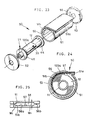
- the cassette body 51 has an arcuate guide piece 51b integrally formed with the interior thereof. By this guide piece 51b, an arcuate guide passage 56 communicated with the film withdrawing mouth 51a is formed.
- the film leader 120a as shown in Fig. 24, is thrusted in the guide passage 56.
- Fig. 25 shows the section of the guide passage 56.
- the guide passage 56 comprises a wide passage 56a and a narrow passage 56b.
- the narrow passage 56a contacts the both side edges of the film strip 120.
- the outer surface of the wide passage 56a is a mat surface on which a number of micro humps and valleys are formed.
- the guide passage 56 is formed to have an arcuate shape and the outer surface of the wide passage 56a is formed into a mat surface, even if light should enter from the film withdrawing mouth 51a, the light would be damped within the guide passage 56 and no photographic fog would be generated to the film roll 12 within the cassette body 51.
- the width W1 of the wide passage 56a is preferably 0.8mm or less in order to maintain the shading function and the width W2 of the narrow passage 56b is preferably 0.2mm or more in order to reduce the friction resistance at the time when the film is fed. Furthermore, the length of the arcuate portion of the guide passage 56 is preferably 5mm or more. Moreover, if the film leader 120a is dyed with a dye having a shading ability or if the outer surface of the film leader 120a is provided with a knurling in order to reduce the reflectance of this portion, the shading function can be more improved.
- the guide passage 56 is provided on one surface thereof with a retaining projecting member 57 and the engaging hole 39 of the film leader 120a is retained in the guide passage 56 by the retaining projecting member 57. If the spool 14 is rotated in the entraining direction of the film leader 120a, the winding diameter of the film roll 12 becomes large. Therefore, the spool 11 is difficult to rotate in this direction. In order to overcome this inconvenience, the engaging projecting member 57 may be omitted.
- the film leader 120a can be fed from the film withdrawing mouth 51a via the guide passage 56. If the rewinding is performed after a photograph is taken, the engaging hole 39 of the film leader 120a is caught by the retaining projecting member 57. Therefore, when the developing treatment is to be started, the film leader 120a can be easily fed outside the cassette body 51 from the exposed film roll 12 by rotating the spool 11.
- FIG. 26 In order to prevent light from entering from the film withdrawing mouth and maintain the film leader in the vicinity of the film withdrawing mouth, the embodiment shown in Fig. 26 may also be applied.
- An elastic shading piece 62 is firmly attached to one inner surface of a film passage 61 communicated with a film withdrawing mouth 60.
- a plastic film sheet dyed with a dye having a shading ability, for example is used. Due to its own elasticity, the shading piece 62 presses the film leader 120a against the other inner surface of the film passage 61 and held it therebetween.
- the film passage 61 may be provided therein with a retaining projecting member 57 for retaining the retaining hole 39 of the film leader 120a so that the position of the film leader 120a is regulated by the retaining projecting member 57 and the engaging hole 39 and the film withdrawing mouth 60 is shaded by the film sheet 62.
- the shading piece 62 which can be used for the above purposes, there are a plastic sheet film attached with a thin metallic plate and a metallic foil, a plastic sheet film deposited with a metal, laminations thereof, etc. This is not necessarily limited to a film-like shape. Furthermore, bent shading pieces 63, 64 and 65 as shown in Figs. 28 through 30 may be used. Moreover, a plurality of shading pieces may be disposed to one side or both sides of the film passage.
- the flange is integrally formed with the spool and the film leader is fed by transmitting the rotation of the spool to the film roll through the flange.
- the manner for feeding the film leader is not necessarily limited to this.
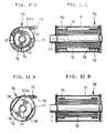
- the film cassette 70 shown in Figs. 31A and 31B is constructed such that an elastic member 72 formed of a sponge is firmly attached to the inner wall of the cassette body 71 in order to press the film roll 12 wound on the spool 11 against the spool 11.
- a lubricant layer is formed on the outer surface of the elastic member 72 in order to reduce the friction resistance between the elastic member 72 and the film.
- a favorable film feeding can be performed if the following relation is always maintained; ⁇ 2 ⁇ ⁇ 1 wherein ⁇ 1 is a coefficient of friction between the lubricant layer 74 and ⁇ 2 is a coefficient of friction between the films.
- a sponge formed of a poly urethane having a thickness of 3mm and compressed at a compressibility of 50% (50g/cm2 pressing) was favorable as a sponge used for the elastic member 72, and a lubricant obtained by attaching "mending tape 810" (merchandise name: manufactured by Sumitomo 3M Ltd. in Japan) to the elastic member 74 was favorable as the lubricant 74.
- a rod-like retaining member 75 is firmly attached to the front end of the film leader 120a in order to hold the film leader 120a at the film withdrawing mouth 73. Therefore, when the film stripe is entrained into the cassette, the film leader 120a is prevented from being drawn into the cassette by the retaining member 75 and the film withdrawing mouth 73 is shaded.
- a plate spring 78 is used as an elastic member for pressing the film roll 12 against the spool 11.
- a silicon manganese steel having a thickness of 0.1mm, for example, is suitable as a material of the plate spring 78. It is preferable that the afore-mentioned "mending tape 810" is used as the lubricant layer 79 formed on the outer surface of the plate spring 78.
- an arcuate rib 86 is integrally formed with the inner wall of the cassette body 85, and the rib 86 is contacted with the outermost periphery of the film roll 12 wound on the spool 11 under pressure. A large friction is not given to the film roll 12 by the rib 86. Also, by virtue of the provision of the rib 86, the winding of the film roll 12 cost periphery of the film roll 12 wound on the spool 11 under pressure. A large friction is not given to the film roll 12 by the rib 86.
- the winding of the film roll 12 can be prevented from being loosened by the rib 86 and when the spool 11 is rotated, the rotation is immediately transmitted to the film leader 120a.
- the film leader 120a is fed outside from the film withdrawing mouth 73 via a film passage 87 having the same configuration as the embodiment shown in Fig. 3.
- the retaining projecting member 57 may be provided to the film passage 87 as in the embodiment shown in Figs. 23 through 25.
Landscapes
- Physics & Mathematics (AREA)
- General Physics & Mathematics (AREA)
- Details Of Cameras Including Film Mechanisms (AREA)
Priority Applications (2)
| Application Number | Priority Date | Filing Date | Title |
|---|---|---|---|
| EP19900100655 EP0436767A3 (en) | 1990-01-12 | 1990-01-12 | Film cassette |
| US07/766,920 US5174519A (en) | 1990-01-12 | 1991-09-27 | Film cassette |
Applications Claiming Priority (1)
| Application Number | Priority Date | Filing Date | Title |
|---|---|---|---|
| EP19900100655 EP0436767A3 (en) | 1990-01-12 | 1990-01-12 | Film cassette |
Publications (2)
| Publication Number | Publication Date |
|---|---|
| EP0436767A2 true EP0436767A2 (fr) | 1991-07-17 |
| EP0436767A3 EP0436767A3 (en) | 1992-08-26 |
Family
ID=8203489
Family Applications (1)
| Application Number | Title | Priority Date | Filing Date |
|---|---|---|---|
| EP19900100655 Withdrawn EP0436767A3 (en) | 1990-01-12 | 1990-01-12 | Film cassette |
Country Status (1)
| Country | Link |
|---|---|
| EP (1) | EP0436767A3 (fr) |
Cited By (4)
| Publication number | Priority date | Publication date | Assignee | Title |
|---|---|---|---|---|
| EP0579228A3 (fr) * | 1992-07-16 | 1994-01-26 | Fuji Photo Film Co., Ltd. | Cassette pour pellicule photographique et procédé d'assemblage de celle-ci |
| US5296886A (en) * | 1993-03-22 | 1994-03-22 | Eastman Kodak Company | Film cassette with spool lock |
| US5317355A (en) * | 1993-03-22 | 1994-05-31 | Eastman Kodak Company | Film cassette with spool lock and light-shielding door |
| US5572272A (en) * | 1993-03-22 | 1996-11-05 | Eastman Kodak Company | Film cassette with spool lock and light-shielding door |
Family Cites Families (8)
| Publication number | Priority date | Publication date | Assignee | Title |
|---|---|---|---|---|
| US3437028A (en) * | 1967-01-25 | 1969-04-08 | Orests B Berlings | Photographic film cassettes and parts thereof |
| US3537376A (en) * | 1967-11-20 | 1970-11-03 | Eastman Kodak Co | Light lock for the entrance/exit passageway of a container for light-sensitive material |
| US3645385A (en) * | 1969-06-20 | 1972-02-29 | Eastman Kodak Co | Openable cartridge for facilitating egress and ingress of strip material |
| US4068809A (en) * | 1976-09-20 | 1978-01-17 | The Singer Company | Filmstrip cartridge with film lock |
| DE2804985A1 (de) * | 1978-02-06 | 1979-08-09 | Geimuplast Mundt Kg Peter | Rollfilmkassette |
| JPH01231045A (ja) * | 1988-03-11 | 1989-09-14 | Fuji Photo Film Co Ltd | 写真フイルムパトローネ |
| US4846418A (en) * | 1988-03-25 | 1989-07-11 | Eastman Kodak Company | Film cassette |
| US4834306A (en) * | 1988-03-25 | 1989-05-30 | Eastman Kodak Company | Film cassette |
-
1990
- 1990-01-12 EP EP19900100655 patent/EP0436767A3/en not_active Withdrawn
Cited By (6)
| Publication number | Priority date | Publication date | Assignee | Title |
|---|---|---|---|---|
| EP0579228A3 (fr) * | 1992-07-16 | 1994-01-26 | Fuji Photo Film Co., Ltd. | Cassette pour pellicule photographique et procédé d'assemblage de celle-ci |
| US5462240A (en) * | 1992-07-16 | 1995-10-31 | Fuji Photo Film Co., Ltd. | Photographic film cassette and method of assembling the photographic film cassette |
| EP0783131A3 (fr) * | 1992-07-16 | 1997-07-16 | Fuji Photo Film Co., Ltd. | Méthode d'assemblage d'une cassette pour films photographiques |
| US5296886A (en) * | 1993-03-22 | 1994-03-22 | Eastman Kodak Company | Film cassette with spool lock |
| US5317355A (en) * | 1993-03-22 | 1994-05-31 | Eastman Kodak Company | Film cassette with spool lock and light-shielding door |
| US5572272A (en) * | 1993-03-22 | 1996-11-05 | Eastman Kodak Company | Film cassette with spool lock and light-shielding door |
Also Published As
| Publication number | Publication date |
|---|---|
| EP0436767A3 (en) | 1992-08-26 |
Similar Documents
| Publication | Publication Date | Title |
|---|---|---|
| EP0414269B1 (fr) | Cassette de film photographique | |
| US5271577A (en) | Photographic film cassette | |
| US5174519A (en) | Film cassette | |
| KR960038521A (ko) | 토너저장용기, 프로세스 카트리지 및 전자사진식 화상형성장치 | |
| EP0436767A2 (fr) | Cassette à film | |
| US5261568A (en) | Apparatus for storing and dispensing pigmented marking particles | |
| JP2801656B2 (ja) | 写真フイルムパトローネ | |
| JPH0315033A (ja) | コマ送りカウント阻止機構 | |
| US5727247A (en) | Camera with film sensor and driver to initiate closing of cassette responsive to return of filmstrip to cassette | |
| US5245376A (en) | Photographic film cassette | |
| EP0406815B1 (fr) | Cassete pour film photographique | |
| US5708854A (en) | One-time-use camera has driver for closing film cassette which is removed with closed cassette to disable camera after completed use | |
| JP2749641B2 (ja) | 写真フイルムパトローネ | |
| US5381980A (en) | Light shielding container for photo-sensitive material | |
| JPH0622851Y2 (ja) | トナー補給装置 | |
| US5564644A (en) | Light shielding magazine for a film cartridge | |
| EP0442501A2 (fr) | Coffret pour bobines de film photographique | |
| JPH1165026A (ja) | 写真フイルムカートリッジ | |
| JPS60104971A (ja) | トナ−補給装置 | |
| JP3165334B2 (ja) | 写真フイルム用スプール | |
| JP2672176B2 (ja) | 写真フイルムパトローネ | |
| JPH03237454A (ja) | 写真フイルムパトローネ | |
| KR100500647B1 (ko) | 렌즈부착사진필름유니트 | |
| JPH028269Y2 (fr) | ||
| US7255298B2 (en) | Magazine and image recording apparatus in which magazine is used |
Legal Events
| Date | Code | Title | Description |
|---|---|---|---|
| PUAI | Public reference made under article 153(3) epc to a published international application that has entered the european phase |
Free format text: ORIGINAL CODE: 0009012 |
|
| AK | Designated contracting states |
Kind code of ref document: A2 Designated state(s): DE FR GB |
|
| PUAL | Search report despatched |
Free format text: ORIGINAL CODE: 0009013 |
|
| AK | Designated contracting states |
Kind code of ref document: A3 Designated state(s): DE FR GB |
|
| STAA | Information on the status of an ep patent application or granted ep patent |
Free format text: STATUS: THE APPLICATION IS DEEMED TO BE WITHDRAWN |
|
| 18D | Application deemed to be withdrawn |
Effective date: 19930227 |