EP0436788A1 - Protection de la colonne vertébrale pour motocycliste en cas d'accident - Google Patents
Protection de la colonne vertébrale pour motocycliste en cas d'accident Download PDFInfo
- Publication number
- EP0436788A1 EP0436788A1 EP90120496A EP90120496A EP0436788A1 EP 0436788 A1 EP0436788 A1 EP 0436788A1 EP 90120496 A EP90120496 A EP 90120496A EP 90120496 A EP90120496 A EP 90120496A EP 0436788 A1 EP0436788 A1 EP 0436788A1
- Authority
- EP
- European Patent Office
- Prior art keywords
- spinal
- plate elements
- base body
- armor according
- armor
- Prior art date
- Legal status (The legal status is an assumption and is not a legal conclusion. Google has not performed a legal analysis and makes no representation as to the accuracy of the status listed.)
- Granted
Links
- 239000000463 material Substances 0.000 claims abstract description 9
- 238000012856 packing Methods 0.000 claims abstract description 5
- 229920006327 polystyrene foam Polymers 0.000 claims abstract description 5
- 239000000945 filler Substances 0.000 claims description 24
- 210000003734 kidney Anatomy 0.000 claims description 9
- 239000002984 plastic foam Substances 0.000 claims description 7
- 241000719239 Oligoplites altus Species 0.000 claims description 4
- 230000000295 complement effect Effects 0.000 claims description 4
- 238000004026 adhesive bonding Methods 0.000 claims description 3
- 239000004698 Polyethylene Substances 0.000 claims description 2
- -1 polyethylene Polymers 0.000 claims description 2
- 229920000573 polyethylene Polymers 0.000 claims description 2
- 239000006260 foam Substances 0.000 claims 1
- 230000006378 damage Effects 0.000 abstract description 5
- 230000002265 prevention Effects 0.000 abstract 1
- 239000004033 plastic Substances 0.000 description 3
- 229920003023 plastic Polymers 0.000 description 3
- 239000004793 Polystyrene Substances 0.000 description 2
- 239000011358 absorbing material Substances 0.000 description 2
- 229920002223 polystyrene Polymers 0.000 description 2
- 230000035939 shock Effects 0.000 description 2
- 101100008049 Caenorhabditis elegans cut-5 gene Proteins 0.000 description 1
- 239000012634 fragment Substances 0.000 description 1
- 238000004519 manufacturing process Methods 0.000 description 1
Images

Classifications
-
- A—HUMAN NECESSITIES
- A63—SPORTS; GAMES; AMUSEMENTS
- A63B—APPARATUS FOR PHYSICAL TRAINING, GYMNASTICS, SWIMMING, CLIMBING, OR FENCING; BALL GAMES; TRAINING EQUIPMENT
- A63B71/00—Games or sports accessories not covered in groups A63B1/00 - A63B69/00
- A63B71/08—Body-protectors for players or sportsmen, i.e. body-protecting accessories affording protection of body parts against blows or collisions
-
- A—HUMAN NECESSITIES
- A41—WEARING APPAREL
- A41D—OUTERWEAR; PROTECTIVE GARMENTS; ACCESSORIES
- A41D13/00—Professional, industrial or sporting protective garments, e.g. surgeons' gowns or garments protecting against blows or punches
- A41D13/05—Professional, industrial or sporting protective garments, e.g. surgeons' gowns or garments protecting against blows or punches protecting only a particular body part
- A41D13/0531—Spine
Definitions
- the invention relates to a spinal armor, in particular as accident protection for motorcyclists, with plate elements arranged one behind the other in the longitudinal direction of the spine and curved outwards, made of deformable material and supported by a deformable base body, which protrude laterally from the spine and at least partially overlap or with little Are spaced from each other.
- Such a spinal armor is known and e.g. described and illustrated in DE 34 41 876 A1.
- This spinal armor is designed essentially in the manner of a kidney belt and carries several, essentially rigid and vertically arranged elements. Each element consists of a slightly convex plate and a molded end piece that is covered by the adjacent element.
- Such a spinal armor is worn on the back in the manner of a kidney belt and protects it in the event of a fall against external forces that can injure the spine.
- This spine armor can be used advantageously by motorcyclists. Only then can the well-known spinal armor function properly meet if the plates, which consist of rigid or semi-rigid and deformable material, can absorb the energy of the shocks as far as possible.
- the plate elements can also be destroyed, whereby they can break into parts with sharp breaking edges. This often leads to considerable cuts because the relatively soft base body does not provide adequate protection. In addition, the plate elements absorb the energy of the impact unfavorably.
- the object is achieved according to the invention in that cavities are formed between the plate elements and the base body and that these cavities are filled with an impact-absorbing filler made of plastic foam.
- the invention is achieved in any case if the base body carries such plate elements which absorb the impact energy in connection with the impact-absorbing filler bodies arranged in between, the destruction of which is certainly accepted.
- the filler absorbs the shock even more by absorbing or converting energy through its deformation or destruction. Fractures of the plate elements do not reach the body directly through the base body of the user.
- the filler between the plate elements and the base body is a kind of intermediate buffer that intercepts the fragments of the plate elements and keeps them away from the body in order to avoid cuts.
- the base body of which has a width that is greater than the width of the plate elements it is expedient if the plate elements have an outwardly concave, material-receiving section, to each of which a leg is connected laterally , which is firmly connected to the base body.
- a further expedient embodiment provides that the respective lower edge of the plate elements, which runs transversely to the longitudinal direction of the spine, has a collar which is at a greater distance from the base body than the concave section and which partially accommodates the transverse upper edge of the adjacent plate element and covers.
- a design of the plate elements makes it possible to cover the spine continuously with polystyrene.
- the areas between the plate elements simultaneously define a type of joint, which are not necessarily connected to one another.
- Another expedient embodiment provides that the plate elements have the same shape.
- a further expedient embodiment provides that the areas of the base body covered by the plate elements have a greater thickness than the areas thereof protruding beyond the plate elements.
- the side of the plate elements facing the base body is provided with a covering or a layer of tear-resistant but deformable material.
- the main task of the covering or the layer is to ensure a good connection between the plate elements and the base body or the filler body in the cavities.
- the filling element can be introduced into the cavities in such a way that the filling element is foamed into the concave portion of the plate elements and is firmly connected to it, or that the filling elements of the plate elements that are lined up are combined to form a one-piece strip which is formed in a hinge-like manner between adjacent plate elements.
- the filler body can also support the entire plate elements towards the base body if it is provided that the filler body also extends over the lateral legs of the plate elements and forms a flat connecting surface towards the base body.
- the spinal armor can be integrated into a jacket as accident protection or designed and worn as a kidney belt.
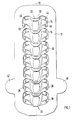
- a spinal armor is shown, which can be incorporated into a leather jacket.
- the spinal armor has plate elements 14, 15, 16 and 18 which are arranged one behind the other in the longitudinal direction 10 of the spine and which are curved outwards and are made of deformable material and are supported by an elastically deformable base body 12 and project laterally beyond the spine.
- the adjacent plate elements 14 and 15 overlap at the transverse edges, the upper plate element, eg 14, and the lower plate element, eg 15, of the spinal armor partially covering each.
- Cavities 20 are formed between the plate elements 14, 15, 16 and 18 connected to the base body 12 and the base body 12 itself. These cavities 20 are filled with an impact-absorbing filler 11 with a low specific weight.
- the base body 12 has a width which is greater than the width of the plate elements 14, 15, 16 and 18.
- the plate elements which are preferably made of elastic plastic, have a concave portion 24 which receives the filler body 11 and on each side of which a leg 26 is located and 28 connects, which is connected to the base body 12 by means of rivets 44, 46, 48 and 50.
- the lower, transverse edge of the plate element 14, 15, 16 and 18 has a collar 30 which is at a greater distance from the base body 12 than the section 24, so that this collar 30 can receive a tapered section 31 of the adjacent plate element.
- the section 24 is completely filled with the filler 11 which is in the form of polystyrene foam and which can be foamed into the section 24 and firmly connected to the plate element 14, 15, 16 and 18.
- Fig. 1 also reveals that the individual plate elements 14, 15, 16 and 18 are themselves connected to one another in the manner of a spine, the tapering section 31 of the one plate element, e.g. 14, from the collar 30 of the adjacent plate element, e.g. 15, is at least partially included.
- the plate elements 14, 15, 16 and 18 can have different shapes. It is crucial that they form a cavity 20 towards the base body 12, which can be easily filled with a filler 11 made of polystyrene foam.
- the base body 12 additionally has two laterally projecting legs 40 and 42, which on the one hand increase the protection of the kidneys and on the other hand can serve as a support for the kidney belt.
- the base body 12 is e.g. from two congruent cuts of plastic foam layers, e.g. are firmly connected by gluing.
- the plate elements 14, 15, 16 and 18 there is a continuous cavity which can also be filled with a single elastically deformable strip as the filler body 11.
- This strip can be designed hinge-like between adjacent plate elements.
- the legs 26 and 28 projecting laterally from the section 24 of the plate elements 14, 15, 16 and 18 lie snugly against the base body 12 and are firmly connected to it.
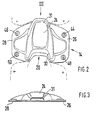
- the plate element 17 has a concavely curved section 70 which can be filled with an impact-absorbing filler 11. Connect to this section 70 there are two laterally projecting legs 66 and 68, which are used for connection to the base body 12. In the axial direction, the plate element 17 has a tapering section 52 on the upper edge, which is connected to the base body 12 by means of the rivets 54 and 56. On the lower edge of the plate element 17, two further projections 62 and 64 are formed, which are connected to the base body 12 by means of the rivets 58 and 60.
- the raised collar 72 is designed such that it covers the section 52 of the adjacent plate element.
- the filling body 11 made of impact-absorbing material can be introduced into each plate element 14, 15, 16 and 18 or 70 in such a way that it forms a flat fastening surface with the legs 26 and 28 or 66 and 68 to the base body 12, as is the cut 5 shows. If the sections 31 and 52 are designed such that a continuous cavity is formed over the spinal armor, then a strip of impact-absorbing material can also be introduced as a filler 11, which extends over all plate elements. The filler 11 can also extend over the legs 26 and 28 or 66 and 68 of the plate elements 14 to 18 and thus support the entire plate elements against the base body 12. This increases the security against additional injuries when the plate elements break.
- the base body 12 itself can be produced as a blank from a plastic foam layer and can also be constructed in multiple layers.
- the spine armor can be incorporated as a unit in the manufacture of a leather jacket, but it can also be designed and worn like a kidney belt as a part separate from the clothing.
- FIGS. 6 and 7 show a spinal armor, the base body 9 of which is made of elastically deformable material and has a series of plate elements 17 and 19, which are lined up, and fillers 8.
- the plate elements 17 and 19 consist of elastically deformable plastic and have rivet bolts 21 which can be inserted into the openings 13. The free ends of the plastic rivet bolts are thermally processed and deformed after attachment of the plate elements 17 and 19, so that a firm connection between the plate elements 17, 19 and the base body 9 is established.
- Each base body 17, 19 has a recess 22 and a projection 23, which is complementary to the recess 22, so that the adjacent plate elements 17, 19 are strung together in at least one position of the spinal armor. It can be seen that the plate elements 17, 19 are essentially V-shaped in their plan view.
- the fillers 8 are shaped such that they fill the cavity 20 between the base body 9 and the respective plate element 17.
- the fillers 8 each have a recess 25 tapering toward the base body 8 with flanks 32, 33 and a respective projection 27 tapering towards the projection 23 of the plate element 17.
- the projection 27 is complementary to the recess 25.
- the abutting surface of two adjacent filler bodies 8 drops from the base body 9 at an angle of approximately 45 °. In this way it is ensured that there is an overlap only with the packing elements, but not with the plate elements 17, 19.
- the packing elements are on all sides of the plate elements surrounded, so that their destruction can only take place if the plate elements are destroyed or extremely deformed.
Landscapes
- Health & Medical Sciences (AREA)
- General Health & Medical Sciences (AREA)
- Physical Education & Sports Medicine (AREA)
- Orthopedic Medicine & Surgery (AREA)
- Engineering & Computer Science (AREA)
- Textile Engineering (AREA)
- Orthopedics, Nursing, And Contraception (AREA)
- Prostheses (AREA)
- Surgical Instruments (AREA)
- Professional, Industrial, Or Sporting Protective Garments (AREA)
Applications Claiming Priority (2)
| Application Number | Priority Date | Filing Date | Title |
|---|---|---|---|
| DE3935828A DE3935828A1 (de) | 1989-10-27 | 1989-10-27 | Wirbelsaeulenpanzer, insbesondere als unfallschutz fuer motorradfahrer |
| DE3935828 | 1989-10-27 |
Publications (2)
| Publication Number | Publication Date |
|---|---|
| EP0436788A1 true EP0436788A1 (fr) | 1991-07-17 |
| EP0436788B1 EP0436788B1 (fr) | 1994-12-21 |
Family
ID=6392368
Family Applications (1)
| Application Number | Title | Priority Date | Filing Date |
|---|---|---|---|
| EP90120496A Expired - Lifetime EP0436788B1 (fr) | 1989-10-27 | 1990-10-25 | Protection de la colonne vertébrale pour motocycliste en cas d'accident |
Country Status (5)
| Country | Link |
|---|---|
| US (1) | US5140995A (fr) |
| EP (1) | EP0436788B1 (fr) |
| AT (1) | ATE115834T1 (fr) |
| DE (1) | DE3935828A1 (fr) |
| ES (1) | ES2066088T3 (fr) |
Cited By (4)
| Publication number | Priority date | Publication date | Assignee | Title |
|---|---|---|---|---|
| WO1994024893A1 (fr) * | 1993-05-05 | 1994-11-10 | Sueur Alexandra C Le | Protection pour le corps |
| ES2070090A1 (es) * | 1993-10-07 | 1995-05-16 | Garcia Juan Garcia | Protector integral de la columna vertebral. |
| EP2062487A2 (fr) | 2007-11-20 | 2009-05-27 | Planet Knox Limited | Protège-dos |
| US7770233B2 (en) | 2002-07-11 | 2010-08-10 | Thomas Rex Haskell | Energy absorbing garment |
Families Citing this family (58)
| Publication number | Priority date | Publication date | Assignee | Title |
|---|---|---|---|---|
| YU50591A (sh) * | 1991-03-22 | 1994-06-10 | Branislav Stojanović | Uredjaj za energetsko aktiviranje sistema kičme |
| US6071257A (en) * | 1991-03-22 | 2000-06-06 | Stojanovic; Branislov | Linkably segmented device having protruding contact elements |
| FR2676178A1 (fr) * | 1991-05-06 | 1992-11-13 | Chevalier Nicolas | Dispositif de protection d'un corps notamment humain ou a animal. |
| DE4228423C1 (fr) * | 1992-08-31 | 1993-09-16 | Fanatic Sports Gmbh & Co Kg, 56242 Selters, De | |
| CA2091140C (fr) * | 1993-03-05 | 2003-01-28 | Frank Arnold Kapounek | Dispositif de protection de la colonne vertebrale |
| US5459878A (en) * | 1993-06-18 | 1995-10-24 | Kombi Ltd. | In-line skate glove suspension system |
| US5586561A (en) * | 1993-12-06 | 1996-12-24 | Entropy Racing, Inc. | Back guard with tunnel for spinal column |
| US5400801A (en) * | 1993-12-06 | 1995-03-28 | Entropy Racing | Back guard |
| DE4415876C2 (de) * | 1994-05-05 | 1998-05-20 | Bayerische Motoren Werke Ag | Rückenprotektor |
| US5840051A (en) * | 1995-08-24 | 1998-11-24 | Towsley; Harold E. | Flexible back, neck and shoulder brace |
| US5724992A (en) * | 1996-01-05 | 1998-03-10 | Ip; Kai | Intra-operative body immobilizer |
| USD435109S (en) * | 1996-01-11 | 2000-12-12 | Branislav Stojanovic | Therapeutic treatment device |
| DE19601151A1 (de) * | 1996-01-15 | 1997-07-17 | Sportema Gmbh | Rückenschutz |
| FI105647B (fi) * | 1996-05-09 | 2000-09-29 | Fashion Group Oy L | Moottoripyöräilijän selkäsuoja |
| US5794261A (en) * | 1997-03-12 | 1998-08-18 | Rawlings Sporting Goods Company, Inc. | Protective joint guard |
| IT243480Y1 (it) * | 1997-07-24 | 2002-03-04 | Dainese Spa | Protettore per la schiena in particolare per motociclisti. |
| US5855561A (en) * | 1997-09-15 | 1999-01-05 | Glidden; Shawn | Back support with freedom of rotary motion |
| US6305031B1 (en) * | 1998-06-12 | 2001-10-23 | Armadillo Sports Design Limited | Protective appliance |
| US6397402B1 (en) * | 1999-08-19 | 2002-06-04 | Hemisphere Group, Inc. | Protective uniform for combination football and skating game and other high-impact applications |
| IT248598Y1 (it) * | 1999-09-10 | 2003-02-06 | Spidi Sport Srl | Scudo per la protezione dorsale. |
| IT1316208B1 (it) * | 2000-09-11 | 2003-04-03 | Dainese Spa | Protettore dorsale a guscio perfezionato, in particolare permotociclisti. |
| ITTV20010113A1 (it) * | 2001-08-10 | 2003-02-10 | Alpinestars Res Srl | Dispositivo liberamente snodato di protezione contro gli urti della schiena |
| US6687920B2 (en) | 2001-09-07 | 2004-02-10 | Salomon, S.A. | Spinal and back protection system |
| USD489845S1 (en) | 2002-07-31 | 2004-05-11 | Dainese S.P.A. | Articulating structure for protecting the spine |
| US7247145B2 (en) * | 2002-09-11 | 2007-07-24 | Studio Moderna Sa | Therapeutic treatment apparatus and method |
| ITPD20020248A1 (it) * | 2002-09-27 | 2004-03-28 | Spyke Srl | Struttura di capo di abbigliamento protettivo. |
| USD512779S1 (en) | 2003-03-07 | 2005-12-13 | Studio Moderna Sa | Multi-column therapeutic treatment device |
| DE10350448B4 (de) * | 2003-10-30 | 2006-11-09 | Adidas International Marketing B.V. | Verstärkungselement |
| GB0327295D0 (en) | 2003-11-24 | 2003-12-24 | Np Aerospace Ltd | Plate assembly |
| USD499846S1 (en) | 2004-02-13 | 2004-12-14 | Studio Moderna Sa | Sports belt |
| US7721348B2 (en) * | 2005-03-08 | 2010-05-25 | Adidas International Marketing B.V. | Protective element |
| US8341763B2 (en) * | 2005-03-30 | 2013-01-01 | Adidas International Marketing B.V. | Reinforcing element |
| DE102005014470B3 (de) * | 2005-03-30 | 2006-09-21 | Adidas International Marketing B.V. | Handschuhverstärkungselement |
| US20080167591A1 (en) * | 2007-01-10 | 2008-07-10 | Ahmed Yahya | Back support |
| US20080282438A1 (en) * | 2007-04-12 | 2008-11-20 | Zine-Eddine Boutaghou | Protective wear having discrete reinforcing elements for improved mobility |
| AU2008243788B2 (en) * | 2007-04-30 | 2012-08-30 | Leatt Corporation | Accessory for inhibiting back injury |
| US20080295231A1 (en) * | 2007-06-01 | 2008-12-04 | Mark Wright | Armored outer garment |
| DE202008007593U1 (de) * | 2008-06-06 | 2009-10-22 | POLO EXPRESSVERSAND Gesellschaft für Motorradbekleidung und Sportswear mbH | Protektor, der am menschlichen Körper getragen wird, mit mehreren schützenden Schichten |
| US8082602B2 (en) * | 2008-08-15 | 2011-12-27 | Sport Maska Inc. | Upper body protective garment |
| JP5117323B2 (ja) * | 2008-08-27 | 2013-01-16 | 本田技研工業株式会社 | 胸部プロテクタ |
| US8074294B2 (en) * | 2008-11-17 | 2011-12-13 | Larry R. Bowlus | Wearable spinal protective apparatus |
| US20110010829A1 (en) * | 2009-07-16 | 2011-01-20 | David Malcolm Norman | Combined neck and upper body protective garment |
| USD626655S1 (en) * | 2009-12-11 | 2010-11-02 | John Rambo | Gravity-operated spine stretcher |
| IT1398462B1 (it) * | 2010-01-28 | 2013-02-22 | Dainese Spa | Dispositivo indossabile di protezione |
| EP2672851B1 (fr) * | 2011-02-07 | 2015-06-17 | Gavin Reay | Armure de protection souple |
| DE102011004039B4 (de) | 2011-02-14 | 2013-02-21 | Adidas Ag | Handgelenkschutz für einen Sporthandschuh |
| DE102011084974B4 (de) * | 2011-10-21 | 2014-01-16 | Uvex Sports Gmbh & Co. Kg | Rückenprotektor mit punktuell fixiertem Dämpfungselement |
| ITVR20120114A1 (it) * | 2012-06-05 | 2013-12-06 | Dainese Spa | Dispositivo indossabile di protezione. |
| US9162090B2 (en) * | 2013-08-01 | 2015-10-20 | Honeywell International Inc. | Lumbar wear-pad |
| US9700122B2 (en) * | 2013-10-22 | 2017-07-11 | Dept. Of The Navy, A U.S. Government Agency, By The U.S. Marine Corps | Central osteoarticular relief and performance structured load distribution system device and modular scalable vest system |
| MY170466A (en) * | 2013-12-10 | 2019-08-02 | Cleary Dolcetti Joseph | Exercise weights |
| USD748420S1 (en) * | 2015-02-23 | 2016-02-02 | Sung Chol Kim | Back and lumbar support |
| WO2017079827A1 (fr) * | 2015-11-09 | 2017-05-18 | Smart Armour Inc. | Dispositif de support vertébral |
| US20180180387A1 (en) * | 2016-12-22 | 2018-06-28 | C.I.A. Miguel Caballero Sas | Body Armor |
| JP7704394B2 (ja) | 2017-05-05 | 2025-07-08 | カプサル テック コープ. | 保護物品とその方法 |
| US11357338B2 (en) * | 2020-05-31 | 2022-06-14 | Paul Anthony Fulcher, JR. | Wearable baby carriers with multiple operation modes, and baby support systems comprising such wearable baby carriers |
| KR102630159B1 (ko) * | 2021-07-16 | 2024-01-29 | 최준혁 | 맞춤형 척추지지장치가 구비된 상의 |
| USD1102669S1 (en) * | 2023-09-12 | 2025-11-18 | INA International Ltd. | Hockey protective pad for back |
Citations (5)
| Publication number | Priority date | Publication date | Assignee | Title |
|---|---|---|---|---|
| DE3319053A1 (de) * | 1983-05-26 | 1984-11-29 | Manfred 5900 Siegen Münker | Sicherheits-oberbekleidungsstueck fuer zweiradfahrer |
| DE8426849U1 (de) * | 1984-09-12 | 1984-12-06 | Frohberg, Holger | Schutzbekleidungsstück, insbesondere Schutzweste für Fahrer und Beifahrer von Krafträdern |
| EP0134727A1 (fr) * | 1983-09-02 | 1985-03-20 | Pierre Verreault | Couverture protectrice pour le dos |
| DE3441876A1 (de) * | 1983-11-23 | 1985-05-30 | Dainese S.P.A., Molvena | Schutzgurt |
| EP0212206A1 (fr) * | 1985-08-02 | 1987-03-04 | Adolf Weigl | Protection de la colonne vertébrale en cas d'accident |
Family Cites Families (11)
| Publication number | Priority date | Publication date | Assignee | Title |
|---|---|---|---|---|
| US2250267A (en) * | 1940-04-02 | 1941-07-22 | Carl G Lins | Back supporter |
| US2342005A (en) * | 1942-06-17 | 1944-02-15 | Mittag George | Luminescent warning device |
| US2418009A (en) * | 1944-12-30 | 1947-03-25 | Berman Hyman | Back-protective surgical suspender vest |
| DE3401111A1 (de) * | 1984-01-14 | 1985-07-18 | Gyula 7032 Sindelfingen Haber | Sicherheitspolster fuer zweiradfahrer, insbesondere motorradfahrer |
| US4599747A (en) * | 1984-09-10 | 1986-07-15 | Robinson Brian W | Breakdance apparel |
| DE3533816A1 (de) * | 1985-09-21 | 1987-04-16 | Adolf Weigl | Unfallschutz-koerperpanzerung |
| US5065457A (en) * | 1987-08-21 | 1991-11-19 | Albion Hat & Cap Company Pty., Ltd. | Body protector |
| US5072738A (en) * | 1989-04-14 | 1991-12-17 | Sorex Medical, A Division Of Sorenson Development, Inc. | Apparatus for protection a wound |
| US5029341A (en) * | 1989-08-22 | 1991-07-09 | Riddell, Inc. | Football shoulder pad |
| US5020156A (en) * | 1989-11-14 | 1991-06-04 | Wilson Sporting Goods Co. | Baseball catcher's chest protector |
| US5056158A (en) * | 1991-04-17 | 1991-10-15 | Liberty Bell Sports Equipment, Inc. | Baseball catcher's hand protector |
-
1989
- 1989-10-27 DE DE3935828A patent/DE3935828A1/de active Granted
-
1990
- 1990-10-25 ES ES90120496T patent/ES2066088T3/es not_active Expired - Lifetime
- 1990-10-25 EP EP90120496A patent/EP0436788B1/fr not_active Expired - Lifetime
- 1990-10-25 AT AT90120496T patent/ATE115834T1/de not_active IP Right Cessation
-
1991
- 1991-04-18 US US07/688,083 patent/US5140995A/en not_active Expired - Fee Related
Patent Citations (5)
| Publication number | Priority date | Publication date | Assignee | Title |
|---|---|---|---|---|
| DE3319053A1 (de) * | 1983-05-26 | 1984-11-29 | Manfred 5900 Siegen Münker | Sicherheits-oberbekleidungsstueck fuer zweiradfahrer |
| EP0134727A1 (fr) * | 1983-09-02 | 1985-03-20 | Pierre Verreault | Couverture protectrice pour le dos |
| DE3441876A1 (de) * | 1983-11-23 | 1985-05-30 | Dainese S.P.A., Molvena | Schutzgurt |
| DE8426849U1 (de) * | 1984-09-12 | 1984-12-06 | Frohberg, Holger | Schutzbekleidungsstück, insbesondere Schutzweste für Fahrer und Beifahrer von Krafträdern |
| EP0212206A1 (fr) * | 1985-08-02 | 1987-03-04 | Adolf Weigl | Protection de la colonne vertébrale en cas d'accident |
Cited By (4)
| Publication number | Priority date | Publication date | Assignee | Title |
|---|---|---|---|---|
| WO1994024893A1 (fr) * | 1993-05-05 | 1994-11-10 | Sueur Alexandra C Le | Protection pour le corps |
| ES2070090A1 (es) * | 1993-10-07 | 1995-05-16 | Garcia Juan Garcia | Protector integral de la columna vertebral. |
| US7770233B2 (en) | 2002-07-11 | 2010-08-10 | Thomas Rex Haskell | Energy absorbing garment |
| EP2062487A2 (fr) | 2007-11-20 | 2009-05-27 | Planet Knox Limited | Protège-dos |
Also Published As
| Publication number | Publication date |
|---|---|
| EP0436788B1 (fr) | 1994-12-21 |
| DE3935828C2 (fr) | 1991-11-07 |
| ATE115834T1 (de) | 1995-01-15 |
| ES2066088T3 (es) | 1995-03-01 |
| US5140995A (en) | 1992-08-25 |
| DE3935828A1 (de) | 1991-05-02 |
Similar Documents
| Publication | Publication Date | Title |
|---|---|---|
| EP0436788B1 (fr) | Protection de la colonne vertébrale pour motocycliste en cas d'accident | |
| EP1632273B1 (fr) | Protège-doigt et gant de sport incorporant ledit protège-doigt | |
| EP0104185B1 (fr) | Amortissement pour skis | |
| DE2707885C2 (de) | Energieabsorbierende Stoßstange für Fahrzeuge, insbesondere Kraftfahrzeuge | |
| DE4409000C2 (de) | Schützer | |
| EP0212206A1 (fr) | Protection de la colonne vertébrale en cas d'accident | |
| DE4302914C2 (de) | Hammer mit stoß-absorbierendem Hammerstiel | |
| DE4430372A1 (de) | Hammer | |
| DE2431302A1 (de) | Energieaksorbierende stosstange | |
| DE2608195C3 (de) | Kinderschaukelsitz | |
| DE102014015536A1 (de) | Haube für eine Kraftfahrzeugkarosserie | |
| DE3228746A1 (de) | Sporthelm | |
| DE6943965U (de) | Armstuetze fuer den innenraum eines kraftfahrzeuges | |
| DE3232762A1 (de) | Schutzhelm | |
| DE3533816C2 (fr) | ||
| DE2850723A1 (de) | Stossfaenger fuer fahrzeuge | |
| DE8324815U1 (de) | Ummantelung von Pfosten, Rohren, Trägern und anderen Hindernissen | |
| DE3709035C2 (fr) | ||
| DE202011109220U1 (de) | Oberkörperprotektor für Nackenprotektoren | |
| DE8912742U1 (de) | Wirbelsäulenpanzer, insbesondere als Unfallschutz für Motorradfahrer | |
| DE3011566C2 (fr) | ||
| DE2258181A1 (de) | Energie absorbierende stosstangenvorrichtung | |
| DE102019207223B4 (de) | Hufeisen | |
| DE9213124U1 (de) | Protektor | |
| DE19825562C2 (de) | Schützer für Sportler |
Legal Events
| Date | Code | Title | Description |
|---|---|---|---|
| PUAI | Public reference made under article 153(3) epc to a published international application that has entered the european phase |
Free format text: ORIGINAL CODE: 0009012 |
|
| 17P | Request for examination filed |
Effective date: 19910405 |
|
| AK | Designated contracting states |
Kind code of ref document: A1 Designated state(s): AT BE CH ES FR GB IT LI LU NL |
|
| 17Q | First examination report despatched |
Effective date: 19930816 |
|
| GRAA | (expected) grant |
Free format text: ORIGINAL CODE: 0009210 |
|
| AK | Designated contracting states |
Kind code of ref document: B1 Designated state(s): AT BE CH ES FR GB IT LI LU NL |
|
| REF | Corresponds to: |
Ref document number: 115834 Country of ref document: AT Date of ref document: 19950115 Kind code of ref document: T |
|
| ITF | It: translation for a ep patent filed | ||
| ET | Fr: translation filed | ||
| GBT | Gb: translation of ep patent filed (gb section 77(6)(a)/1977) |
Effective date: 19950112 |
|
| REG | Reference to a national code |
Ref country code: CH Ref legal event code: PFA Free format text: HEIN GERICKE GMBH |
|
| PGFP | Annual fee paid to national office [announced via postgrant information from national office to epo] |
Ref country code: ES Payment date: 19951023 Year of fee payment: 6 Ref country code: CH Payment date: 19951023 Year of fee payment: 6 |
|
| PLBE | No opposition filed within time limit |
Free format text: ORIGINAL CODE: 0009261 |
|
| STAA | Information on the status of an ep patent application or granted ep patent |
Free format text: STATUS: NO OPPOSITION FILED WITHIN TIME LIMIT |
|
| 26N | No opposition filed | ||
| REG | Reference to a national code |
Ref country code: ES Ref legal event code: PC2A Owner name: HEIN GERICKE GMBH |
|
| NLS | Nl: assignments of ep-patents |
Owner name: HEIN GERICKE G.M.B.H. |
|
| PG25 | Lapsed in a contracting state [announced via postgrant information from national office to epo] |
Ref country code: ES Free format text: LAPSE BECAUSE OF EXPIRATION OF PROTECTION Effective date: 19961026 |
|
| PG25 | Lapsed in a contracting state [announced via postgrant information from national office to epo] |
Ref country code: LI Effective date: 19961031 Ref country code: CH Effective date: 19961031 |
|
| PGFP | Annual fee paid to national office [announced via postgrant information from national office to epo] |
Ref country code: LU Payment date: 19961101 Year of fee payment: 9 |
|
| REG | Reference to a national code |
Ref country code: CH Ref legal event code: PL |
|
| PGFP | Annual fee paid to national office [announced via postgrant information from national office to epo] |
Ref country code: GB Payment date: 19971006 Year of fee payment: 8 |
|
| PGFP | Annual fee paid to national office [announced via postgrant information from national office to epo] |
Ref country code: FR Payment date: 19971016 Year of fee payment: 8 |
|
| PGFP | Annual fee paid to national office [announced via postgrant information from national office to epo] |
Ref country code: BE Payment date: 19971021 Year of fee payment: 8 Ref country code: AT Payment date: 19971021 Year of fee payment: 8 |
|
| PGFP | Annual fee paid to national office [announced via postgrant information from national office to epo] |
Ref country code: NL Payment date: 19971029 Year of fee payment: 8 |
|
| PG25 | Lapsed in a contracting state [announced via postgrant information from national office to epo] |
Ref country code: LU Free format text: LAPSE BECAUSE OF NON-PAYMENT OF DUE FEES Effective date: 19981025 Ref country code: GB Free format text: LAPSE BECAUSE OF NON-PAYMENT OF DUE FEES Effective date: 19981025 Ref country code: AT Free format text: LAPSE BECAUSE OF NON-PAYMENT OF DUE FEES Effective date: 19981025 |
|
| PG25 | Lapsed in a contracting state [announced via postgrant information from national office to epo] |
Ref country code: BE Free format text: LAPSE BECAUSE OF NON-PAYMENT OF DUE FEES Effective date: 19981031 |
|
| BERE | Be: lapsed |
Owner name: HEIN GERICKE G.M.B.H. Effective date: 19981031 |
|
| PG25 | Lapsed in a contracting state [announced via postgrant information from national office to epo] |
Ref country code: NL Free format text: LAPSE BECAUSE OF NON-PAYMENT OF DUE FEES Effective date: 19990501 |
|
| GBPC | Gb: european patent ceased through non-payment of renewal fee |
Effective date: 19981025 |
|
| PG25 | Lapsed in a contracting state [announced via postgrant information from national office to epo] |
Ref country code: FR Free format text: LAPSE BECAUSE OF NON-PAYMENT OF DUE FEES Effective date: 19990630 |
|
| NLV4 | Nl: lapsed or anulled due to non-payment of the annual fee |
Effective date: 19990501 |
|
| REG | Reference to a national code |
Ref country code: ES Ref legal event code: FD2A Effective date: 19990601 |
|
| REG | Reference to a national code |
Ref country code: FR Ref legal event code: ST |
|
| PG25 | Lapsed in a contracting state [announced via postgrant information from national office to epo] |
Ref country code: IT Free format text: LAPSE BECAUSE OF NON-PAYMENT OF DUE FEES;WARNING: LAPSES OF ITALIAN PATENTS WITH EFFECTIVE DATE BEFORE 2007 MAY HAVE OCCURRED AT ANY TIME BEFORE 2007. THE CORRECT EFFECTIVE DATE MAY BE DIFFERENT FROM THE ONE RECORDED. Effective date: 20051025 |