EP0436843A1 - Reduzierung einer durch Relaxation induzierter Spannungsvariation in Befestigungselementen - Google Patents
Reduzierung einer durch Relaxation induzierter Spannungsvariation in Befestigungselementen Download PDFInfo
- Publication number
- EP0436843A1 EP0436843A1 EP90123537A EP90123537A EP0436843A1 EP 0436843 A1 EP0436843 A1 EP 0436843A1 EP 90123537 A EP90123537 A EP 90123537A EP 90123537 A EP90123537 A EP 90123537A EP 0436843 A1 EP0436843 A1 EP 0436843A1
- Authority
- EP
- European Patent Office
- Prior art keywords
- torque
- fastener
- rec
- predetermined number
- joint
- Prior art date
- Legal status (The legal status is an assumption and is not a legal conclusion. Google has not performed a legal analysis and makes no representation as to the accuracy of the status listed.)
- Withdrawn
Links
Images

Classifications
-
- B—PERFORMING OPERATIONS; TRANSPORTING
- B25—HAND TOOLS; PORTABLE POWER-DRIVEN TOOLS; MANIPULATORS
- B25B—TOOLS OR BENCH DEVICES NOT OTHERWISE PROVIDED FOR, FOR FASTENING, CONNECTING, DISENGAGING, OR HOLDING
- B25B23/00—Details of, or accessories for, spanners, wrenches, screwdrivers
- B25B23/14—Arrangement of torque limiters or torque indicators in wrenches or screwdrivers
-
- G—PHYSICS
- G05—CONTROLLING; REGULATING
- G05D—SYSTEMS FOR CONTROLLING OR REGULATING NON-ELECTRIC VARIABLES
- G05D17/00—Control of torque; Control of mechanical power
- G05D17/02—Control of torque; Control of mechanical power characterised by the use of electric means
-
- Y—GENERAL TAGGING OF NEW TECHNOLOGICAL DEVELOPMENTS; GENERAL TAGGING OF CROSS-SECTIONAL TECHNOLOGIES SPANNING OVER SEVERAL SECTIONS OF THE IPC; TECHNICAL SUBJECTS COVERED BY FORMER USPC CROSS-REFERENCE ART COLLECTIONS [XRACs] AND DIGESTS
- Y10—TECHNICAL SUBJECTS COVERED BY FORMER USPC
- Y10T—TECHNICAL SUBJECTS COVERED BY FORMER US CLASSIFICATION
- Y10T29/00—Metal working
- Y10T29/49—Method of mechanical manufacture
- Y10T29/49764—Method of mechanical manufacture with testing or indicating
- Y10T29/49766—Method of mechanical manufacture with testing or indicating torquing threaded assemblage or determining torque herein
- Y10T29/49767—Determining relative number of threaded member rotations
-
- Y—GENERAL TAGGING OF NEW TECHNOLOGICAL DEVELOPMENTS; GENERAL TAGGING OF CROSS-SECTIONAL TECHNOLOGIES SPANNING OVER SEVERAL SECTIONS OF THE IPC; TECHNICAL SUBJECTS COVERED BY FORMER USPC CROSS-REFERENCE ART COLLECTIONS [XRACs] AND DIGESTS
- Y10—TECHNICAL SUBJECTS COVERED BY FORMER USPC
- Y10T—TECHNICAL SUBJECTS COVERED BY FORMER US CLASSIFICATION
- Y10T29/00—Metal working
- Y10T29/49—Method of mechanical manufacture
- Y10T29/49826—Assembling or joining
- Y10T29/49863—Assembling or joining with prestressing of part
Definitions
- This invention relates to tightening methods for threaded fasteners and in particular to a tightening method for reducing the variation in fastener tensions resulting from relaxation.
- threaded fasteners include: bolts and nuts, bolts received in tapped holes, studs with nuts, and the like.
- the fasteners and the elements that are fastened together are collectively termed a joint.
- fastener tension may be preferred as limited by the proof strength of the fastener.
- fastener tension In joints subject to axial load, i.e., directed along the shank of the fastener, fastener tension must be limited so that the yield strength of the fastener is not exceeded under peak loads. Fluctuating axial loads, which may induce fatigue in the fastener, place different limits on the optimal tension in the fastener.
- Fastener tension is difficult to measure directly. Instrumented bolts, load washers and certain ultrasonic techniques have all been used to provide essentially direct indications of fastener tension, however, these techniques are expensive or time consuming and generally not feasible in production environments. Fastener tension is instead, more typically deduced from measurements of fastener torque, such as in “torque control methods” or measurements of the angle of rotation of the fastener, such as in "turn-of-the-nut methods". Both fastener torque and angle of rotation can be easily observed during the assembly of the joint.
- fastener torque and tension is highly dependant on the coefficient of friction between the fastener and the elements of the joint to be fastened. This coefficient of friction varies considerably between joints for reasons including variations in surface coatings or lubrication of the fastener as well as imperfections in the fastener threads.
- angle of rotation of the fastener and the fastener tension is correspondingly dependant on the relative stiffness of the joint elements and the fastener, quantities that also vary considerably between joints.
- LRM logarithmic rate method
- uniformity of fastener tension is also critical. Uniform fastener tension prevents distortion of the joint elements and ensures that each fastener efficiently shares the load placed on the joint. Sophisticated fastener tightening schedules, such as LRM, improve uniformity of fastener tension by increasing the accuracy of fastener tension under variations in joint friction and stiffness.
- Tension relaxation appears to have two components which may be termed: “quick relaxation” and “time relaxation”. Quick relaxation occurs very shortly after the applied torque is removed from the fastener 36 and is thought to result from a slight unwinding of the fastener 36 produced from relaxation of torsional stress in the fastener shank. Second order elasticity terms in the elasticity of the fastener shank, as opposed to the first order term of Hook's law, may also produce this loss of tension with loss of torsion.
- Time relaxation occurs over a longer period of time and is believed to be caused by plastic flow or creep of the joint 34 materials themselves, including gasket 42 , and may occur over the span of several minutes to several days.
- Dynamic torque as used herein, will be defined as the final torque achieved in the initial tightening of the fastener yet while the fastener is still turning at a tightening speed which is substantially higher than the previously mentioned reference speed of the static audit.
- a static audit is ordinarily conducted with a hand-held torque wrench.
- the torque on the fastener is slowly increased until the fastener breaks free.
- the maximum torque on the wrench is then recorded. Measurements of static torque will vary depending on the speed with which the fastener is turned and the distance it travels, neither of which may be easily controlled by hand. Joints that break violently, or very hard joints requiring large torques (200 Nm or greater) can be difficult to audit by hand. Operator fatigue may lead to errors.
- the torque wrench only records only a single peak torque, so it cannot be determined whether the breakaway torque or the torque rise due to angular advance was measured.
- the present invention relates to a tightening method that includes a torque recovery cycle appended to the end of an initial tightening cycle of a threaded fastener.
- the breaking of the joint is ensured by measuring the dynamic torque last applied to the fastener during the initial tightening cycle. After the relaxation time, an increasing torque is applied to the fastener and this torque is periodically sampled. When a predetermined number of torque samples measure higher than the dynamic torque last applied to the fastener, the fastener is rotated through an additional predetermined angle.
- This method of ensuring that the joint breaks also ensures that fasteners with low torques are retorqued to at least the dynamic torque.
- the torque recovery cycle is performed at a low reference speed, and torque and angle data are sampled and stored. From these samples, a point of minimum curvature between adjacent samples may be determined. The highest torque sample following a predetermined number of samples after this point of minimum curvature is recorded as the static torque value. This method eliminates reporting the breakaway torque which could be substantially higher than the torque values that follow.
- a joint 34 is comprised of a bolt 36 extending through a hole in a top plate 40 and received by a threaded hole in a chassis 44. Sandwiched between the top plate 40 and the chassis 44 is, in some applications, a gasket 42. The head of the bolt 36 is received by a socket 38 attached to an instrumented electric nutrunner 10, of a type commercially available and to be described below.
- the nutrunner 10 suitable for practice of the present invention, includes a brushless DC motor 12 controlled by motor controller 22.
- Motor controller 22 applies power from power supply 24 to the motor 12 windings (not shown) according to rotor position signals 18 received from a resolver 16 connected to one end of the motor 12 by shaft 25.
- the rotor position signal 18 may be processed by the motor controller 22 to produce a tachometer signal to provide feedback control of the speed of the nutrunner 10 as is understood in the art.
- the other end of the motor 12 is connected by shaft 25 to the nutrunner socket 38 through a torque transducer/reduction gearbox 14 which provides a torque signal 20 from a strain gauge torque sensor (not shown) incorporated in the torque transducer/reduction gearbox 14 and produces a digital angle signal 19 via an angle encoder (also not shown).
- the torque signal 20 and the digital angle signal 19 are transmitted to the spindle module 26.
- the torque transducer/reduction gearbox 14 also reduces the relative speed of the rotation of socket 38 with respect to the motor shaft 25 by means of a planetary gear train (not shown).
- the resolution of the angle signal 19 varies between approximately 0.1 and 2.0 degrees of socket 38 rotation depending on the gearing of the planetary gear train incorporated into the torque transducer/reduction gearbox 14 and the desired value as imput to the station controller 28.
- the digital angle signal 19 is produced by a hall effect magnetic sensor as is understood in the art.
- the spindle module 26 interprets, samples and stores the torque and angle signals 20 and 19 respectively.
- the spindle module 26 contains a 68000 CMOS microprocessor manufactured by Motorola, 16 kilobytes of static random access memory (“SRAM”) for torque and angle data storage, and 64 kilobytes of erasable programmable read only memory (“EPROM”) for program instruction.
- SRAM static random access memory
- EPROM erasable programmable read only memory
- the spindle module 26 contains 2 kilobytes of non-volatile random access memory (“RAM”) for parameter storage to be described below.
- the spindle module 26 receives instructions from a station controller module 28 through a "down load” process.
- the spindle module 26 controls the fastener tightening cycle and the torque recovery cycle by means of a program, described below only with respect to the torque recovery cycle.
- the fastener tightening cycle and torque recovery cycle program receive inputs of fastener torque and angle from the nutrunner 10.
- the station controller module 28 also incorporates a CMOS 68000 microprocessor, 192 kilobytes of non volatile RAM and 512 kilobytes of EPROM for program storage as is generally understood in the art.
- the station controller module 28 has two RS-232 serial ports for connecting to configuration terminals 30 and an RS-485 port for linking the station controller module 28 to a network 32 to provide fastening data access from remote terminals 30.
- the configuration terminal 30 may be used by an operator to select various tightening and torque recovery parameters, the latter to be discussed below.
- the initial tightening of the fastener 36 shows a general upward slope as the torque increases with increasing turn of the fastener 36.
- This increasing torque results, principally, from the increasing compression of the joint 34.
- the rotation of the fastener 36 will stop at some angle 50 and at some dynamic torque, T d , at or near a target or set point torque T sp .
- the dynamic torque T d is defined as the resistive torque counteracting the torque of the nutrunner 10 at typical production tightening speeds.
- the initial tightening cycle may be performed under any of a variety of methods including torque control, turn-of-the-nut, and the LRM systems referred to above.
- curve 48 Following the relaxation time, torque is re-applied to the fastener 36 as represented by curve 48.
- the initial portion of curve 48 represents nutrunner 10 "wind-up" and corresponds to the elastic deflection of the nutrunner 10 transmission components under torsional stress. During this wind-up, the fastener 36 is not moving, however the windup causes the angle encoder 14 to register a slight angular advance.
- T b the fastener 36 begins to move and the torque drops to a minimum static value T s0 .
- the static torque is the fastener's resistive torque at a low reference rotational speed that is much lower than the tightening speed producing T d .
- the static torque T s0 is defined at angle 0 , the angle at which the fastener begins to move.after breakaway torque T b . This definition reflects the fact that static torque will continue to increase with increasing fastener rotation.
- T s0 is shown lower than T b , in some cases, T s0 will be equal to T b .
- T s0 also is shown lower than T d , in part, as a result of relaxation of the joint. As a general rule, if there is no relaxation the converse will be true: the dynamic torque T d will be lower than the static torque T s .
- the torque rapidly increases over the next few degrees of fastener rotation to a peak static torque value T s ⁇ .
- the static torque T s ⁇ is defined in terms of an angle ⁇ reflecting the fact that static torque will continue to increase with increasing fastener rotation.
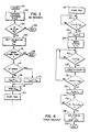
- the torque recovery cycle of the present invention is controlled by a program running on the spindle module 26, with input torque and angle data from the nutrunner 10 as processed by the spindle module 26, and with parameters input by the operator through configuration terminal 30.
- the torque recovery cycle starts after the initial fastener tightening cycle of the joint 34 as represented by process block 102.
- This initial tightening cycle 102 may be performed according to any number of methods known in the art including torque control, turn-of-the-nut and LRM, as previously described, provided that the final dynamic torque value T d , reached by the fastener 34, may be measured.
- a recovery flag is examined to see if torque recovery should be executed.
- the torque recovery cycle is optional and may be omitted in situations where little advantage is derived.
- the torque recovery flag is stored in the station controller module memory and may be set or reset by command from the operator via the configuration terminal 30.
- the torque recovery program proceeds to process block 108.
- the program waits for a length of time equal to a relaxation time parameter t rec , which may be set by the operator. Longer periods t rec are preferable, all else being equal, as they allow more time for relaxation to occur and hence allow more complete torque recovery. Shorter periods t rec , however, may be required to maintain practical production rates because t rec directly affects cycle time. As noted, however, significant reductions in torque scatter may be obtained with a t rec value of 2 to 5 seconds.
- the program exits as indicated by exit block 106.
- any error flags that were set in the fastener tightening cycle 102 are inspected.
- the error flags are stored in the spindle module 26 and if set indicate that an error occurred in the fastener tightening cycle.
- the particular errors that are possible depend on the tightening strategy adopted in process block 102 but may include, for example, indications of: cross threading of the fastener 36 or metal chips in the threads causing galling; collapse of the joint 34 as in the case of a clevis joint; or a broken or missing fastener 36.
- Such errors are generally detected by observing the fastener tightening cycle torque-angle curve or "signature" according to methods known in the art.
- the program is exited at process block 106, except if the error is one of "low final torque" alone. Most errors obviate the need for a torque recovery cycle, however, the error of low final torque may be remedied.
- a recovery torque variable T rec is set equal to the set point torque T sp used in the initial fastener tightening cycle 102, per process block 114. Otherwise, if there are no errors, the recovery torque variable T rec is set equal to the final dynamic torque T d experienced by the fastener in the initial tightening cycle 102, per process block 116. In certain tightening strategies, such as turn-of-the-nut, there is no T sp value produced. In these situations, there will be no corresponding low torque error. If there is, then T sp is defined as the minimum allowable torque T rec .
- T rec is used to identify the point at which the joint breaks, which is generally near T d , the final torque value of the joint. If the joint torque is too low, torque reocvery first re-torques the fastener 36 to the correct torque value and then adds the angle of advance ⁇ rec. Setting T rec equal to T sp accomplishes this torque correction as will be seen.
- the maximum angular velocity of the nutrunner 10 is set equal to a recovery speed indicated by parameter N rec which again may be set by the operator.
- N rec is chosen to be a low speed commensurate with the measurement of static rather than dynamic torque. N rec should be sufficiently low so that "impacting" and subsequent torque transients are minimized.
- a typical value for N rec is 5 rpm.
- the nutrunner is energized per process block 120 to continue to turn in the direction of "tightening" of the fastener.
- instantaneous torque values T i from the torque transducer 14, as processed by the spindle module 26, are compared to a value equal to 1 ⁇ 4 T rec per process block 122. If the values of T i do not exceed 1 ⁇ 4 T rec within a given time as determined by a watchdog time value, the program exits (not shown).
- the watch dog time value prevents endless loops of the program in the event that the nutrunner 10 is no longer engaged with the fastener 36, for example.
- the frequency of the sampling of torque and angle values may be controlled by the operator but are generally equal to approximately one sample per 0.5 degrees.
- variable ⁇ e like the watch dog timer value is also used to prevent endless loops of the program at decision blocks 126, 130 and 136 discussed below. If the torque recovery cycle is not accomplished within 120° of ⁇ e the program is exited under the assumption that either the joint is yielding or engagement is lost.
- the torque values T i and angle values ⁇ i are now stored in the spindle RAM per process block 124 for later processing to determine the static torque T s ⁇ as will be described below.
- the storing process is carried on as a background task (not shown in Figure 4) and includes the comparison of values ⁇ i to ⁇ e to detect endless loops of the program as described above.
- a count variable previously set to zero, is incremented for each time a torque sample T i equals or exceeds T rec .
- this count variable is compared to a parameter n rec and if count is less than n rec then the program loops back to decision block 126 to evaluate the next torque sample T i .
- Decision block 130 therefore, evaluates the number of samples T i which have had values greater than T rec . Note that the samples T i need not be consecutive.
- n rec number of torque samples T i be greater than T rec before the program advances is intended to confirm that all relaxation is taken up before advancing by ⁇ rec .
- the parameter n rec has a typical value of three but this value may be changed by the operator through the configuration terminal 30 depending on the characteristics of the torque-angle curve produced by the joint 34.
- n rec torque values T i greater than T rec have been observed then the program loops back to decision block 126 to evaluate the next torque sample T i . Otherwise, the program proceeds to process block 132 and the current angular position of the fastener ⁇ i is stored at ⁇ 0 .
- the variable ⁇ 0 is the angular reference point for breaking the joint 34.
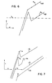
- the torque-angle curves 160 and 162 of two example joints are shown.
- the points at which torque and angle samples T i and ⁇ i are taken are shown by dots and the points ⁇ 0 for these curves are also shown.
- ⁇ 0 is assigned to the third point where T i is greater than T d regardless of whether there are intervening points T i less than T d .
- the difference between ⁇ 0 and the current ⁇ i is evaluated. If this difference is greater than ⁇ rec then the nutrunner 10 is deenergized and the torque recovery cycle is complete per process block 138. If the difference between ⁇ 0 and the current ⁇ i is less than parameter ⁇ rec then the nutrunner motion is continued. The net effect is that the nutrunner advances by angle ⁇ rec after n rec torque samples T i have exceeded T rec .
- a typical value for ⁇ rec is 3°, however this value may be changed by the operator by means of configuration console 30.
- ⁇ rec should be as small a value as possible that ensures that the joint 34 will break. This value will vary depending on the joint characteristics, but typically ranges from 1° to 6°.
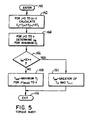
- the "n" samples of torque and angle data T i and ⁇ i acquired in the torque recovery cycle are stored for determining the static torque of the joint T s ⁇ for quality control purposes.
- the index value "j m " corresponding to the minimum curvature C j is determined per process block 144.
- the curvature value C j may be understood to be a discrete point equivalent to the second derivative of torque with respect to angle: If the torque-angle curve near T j is concave in a downward direction, the C j associated with T j will be negative. If the torque-angle curve near T j is concave in an upward direction, the C j associated with T j will be positive. Sharper bends in the torque-angle curve will have higher-magnitude C j values.
- the point of minimum curvature considering the sign as well as the magnitude of the curvature C j , is shown for three example torque-angle curves near the point at which the joint 34 breaks.
- Curve 170 shows a joint 34 exhibiting a steady increase in torque with angle.
- the point of minimum curvature j m is at the transition between high slope and low slope, or the "kink", on this curve.
- Torque-angle curve 176 is representative of a more typical joint where the torque increases to the breakpoint and then decreases again finally rising slowly.
- the point of minimum curvature j m for this curve is the local torque maximum between the rising and falling sections of the curve.
- Curve 174 shows a torque angle curve with slip sticking: an undulating curve with several local maxima. Here the sharpest local maximum will be the point of minimum curvature j m . This latter type of curve 174 may not yield consistent static torque measurements under the present method, however it may be possible to reduce tool recovery speed N rec to reduce such chattering.
- the index value of minimum curvature j m is found, it is evaluated to determine its location within the sample points. If j m +2 is less than or equal to the total number of sampled points "n", as evaluated per decision block 146, then the static torque T s ⁇ is set equal to the maximum torque sample T i following index value j m +2 as indicated by process block 150. On the other hand, if j m +2 is greater than the total number of sampled points "n", then the static torque T s ⁇ is assigned the maximum torque of T n-1 and T n , the last two sampled torque values, as indicated by process block 148. The reason for this method of peak torque detection is to exclude the breakaway which is not a good indication of the initial torque applied.
- the improvement in scatter as represented by the standard deviation is 3.69:1, and 3.38:1 as represented by the range.
- the improvement in scatter as represented by the standard deviation is 1.67:1 and 1.62:1 as represented by the range.
Landscapes
- Engineering & Computer Science (AREA)
- Physics & Mathematics (AREA)
- General Physics & Mathematics (AREA)
- Automation & Control Theory (AREA)
- Mechanical Engineering (AREA)
- Details Of Spanners, Wrenches, And Screw Drivers And Accessories (AREA)
- Force Measurement Appropriate To Specific Purposes (AREA)
Applications Claiming Priority (2)
| Application Number | Priority Date | Filing Date | Title |
|---|---|---|---|
| US461633 | 1990-01-08 | ||
| US07/461,633 US4995145A (en) | 1990-01-08 | 1990-01-08 | Reduction of relaxation induced tension scatter in fasteners |
Publications (1)
| Publication Number | Publication Date |
|---|---|
| EP0436843A1 true EP0436843A1 (de) | 1991-07-17 |
Family
ID=23833342
Family Applications (1)
| Application Number | Title | Priority Date | Filing Date |
|---|---|---|---|
| EP90123537A Withdrawn EP0436843A1 (de) | 1990-01-08 | 1990-12-07 | Reduzierung einer durch Relaxation induzierter Spannungsvariation in Befestigungselementen |
Country Status (3)
| Country | Link |
|---|---|
| US (1) | US4995145A (de) |
| EP (1) | EP0436843A1 (de) |
| JP (1) | JPH04152071A (de) |
Cited By (4)
| Publication number | Priority date | Publication date | Assignee | Title |
|---|---|---|---|---|
| EP0572330A3 (de) * | 1992-05-19 | 1993-12-08 | GOVERNMENT OF THE UNITED STATES OF AMERICA as represented by THE ADMINISTRATOR OF THE NATIONAL AERONAUTICS AND SPACE ADM. | Auswertungsvorrichtung für Bolzen und Mutter |
| EP0771250A4 (de) * | 1994-05-12 | 1997-03-13 | A Erich Neuffer | Dual-spitzendrehmoment messeinrichtung |
| WO2000038879A1 (en) * | 1998-12-29 | 2000-07-06 | Atlas Copco Tools Ab | Method for pretensioning a joint containing two or more threaded fasteners |
| EP1008423A3 (de) * | 1998-12-10 | 2001-05-02 | Atlas Copco Tools Ab | Angetriebenes Werkzeug mit programmierbarer Steuerungseinheit |
Families Citing this family (21)
| Publication number | Priority date | Publication date | Assignee | Title |
|---|---|---|---|---|
| GB8901918D0 (en) * | 1989-01-28 | 1989-03-15 | Franks Casing Crews Uk Limited | Control system |
| US5216795A (en) * | 1989-09-22 | 1993-06-08 | Atlas Copco Tools Ab | Method for tightening threaded joints |
| US5383370A (en) * | 1991-04-09 | 1995-01-24 | Sanyo Machine America Corporation | Device for verifying a minimum torque value |
| US5315501A (en) * | 1992-04-03 | 1994-05-24 | The Stanley Works | Power tool compensator for torque overshoot |
| SE506118C2 (sv) * | 1993-09-02 | 1997-11-10 | Atlas Copco Tools Ab | Metod för åtdragning av gängade förband till en önskad förspänningsnivå med hjälp av en manuellt manövrerad kraftmutterdragare innefattande en nedgängningsfas och en förspänningsfas, avkänning av momentmotståndet i förbandet samt avbrytande av rotationen vid uppnådd önskad förspänningsnivå |
| US5581042A (en) * | 1995-12-11 | 1996-12-03 | Ingersoll-Rand Company | Method for torque wrench non-contact angle measurement |
| US20080178713A1 (en) * | 2007-01-31 | 2008-07-31 | Robert Earl Long | Fastener tightening system utilizing identification technology |
| DE102007019409B3 (de) * | 2007-04-23 | 2008-11-13 | Lösomat Schraubtechnik Neef Gmbh | Kraftschrauber |
| SE532792C2 (sv) * | 2007-07-13 | 2010-04-13 | Atlas Copco Tools Ab | Regulator för kraftverktyg |
| US8269612B2 (en) | 2008-07-10 | 2012-09-18 | Black & Decker Inc. | Communication protocol for remotely controlled laser devices |
| JP2012045665A (ja) * | 2010-08-26 | 2012-03-08 | Toyota Motor Corp | 打撃式締め付け工具 |
| US9908182B2 (en) | 2012-01-30 | 2018-03-06 | Black & Decker Inc. | Remote programming of a power tool |
| US20130327552A1 (en) | 2012-06-08 | 2013-12-12 | Black & Decker Inc. | Power tool having multiple operating modes |
| US8919456B2 (en) | 2012-06-08 | 2014-12-30 | Black & Decker Inc. | Fastener setting algorithm for drill driver |
| US9022135B2 (en) * | 2012-10-02 | 2015-05-05 | Stanley Black & Decker, Inc. | Torque-applying tool and torque controller therefor |
| US10011006B2 (en) | 2013-08-08 | 2018-07-03 | Black & Decker Inc. | Fastener setting algorithm for drill driver |
| US10513018B2 (en) | 2014-09-18 | 2019-12-24 | Atlas Copco Tools & Assembly Systems, Llc | Adaptive U-bolt joint stabilization process |
| US9839998B2 (en) * | 2015-04-07 | 2017-12-12 | General Electric Company | Control system and apparatus for power wrench |
| CN108746733B (zh) * | 2018-05-30 | 2019-09-24 | 中国航发动力股份有限公司 | 一种航空发动机盘件孔内壁表面完整性加工过程监控方法 |
| CN109693103B (zh) * | 2019-03-01 | 2024-02-27 | 西格迈股份有限公司 | 底阀螺母定扭力锁紧设备及其使用方法 |
| SE545829C2 (en) * | 2022-10-20 | 2024-02-13 | Atlas Copco Ind Technique Ab | Control device and method for determining a joint identity of a tightened joint |
Citations (5)
| Publication number | Priority date | Publication date | Assignee | Title |
|---|---|---|---|---|
| US4305471A (en) * | 1979-04-19 | 1981-12-15 | Rockwell International Corporation | Simplified fastening technique using the logarithmic rate method |
| US4403663A (en) * | 1981-04-13 | 1983-09-13 | Wolff Manufacturing Company | Power-operated torque wrench |
| DE3230642A1 (de) * | 1982-08-18 | 1984-02-23 | Volkswagenwerk Ag, 3180 Wolfsburg | Verfahren und vorrichtung zum anziehen eines ein gewinde tragenden verbindungselements |
| EP0291215A2 (de) * | 1987-05-11 | 1988-11-17 | Ingersoll-Rand Company | Anziehen einer Dichtungsverbindung |
| EP0340999A1 (de) * | 1988-05-02 | 1989-11-08 | Ingersoll-Rand Company | Regelung der Dichtungsstärkeverminderung mit spannungsabhängiger Rückkopplung |
Family Cites Families (15)
| Publication number | Priority date | Publication date | Assignee | Title |
|---|---|---|---|---|
| US4000782A (en) * | 1974-09-19 | 1977-01-04 | Standard Pressed Steel Co. | Tightening system with quality control apparatus |
| US3973434A (en) * | 1974-09-19 | 1976-08-10 | Standard Pressed Steel Co. | Tightening system with quality control apparatus |
| US4095325A (en) * | 1974-12-24 | 1978-06-20 | Sanyo Machine Works, Ltd. | Method for tightening bolts |
| US4023406A (en) * | 1976-03-31 | 1977-05-17 | Standard Pressed Steel Co. | Tightening system with torque-time control |
| US4106570A (en) * | 1977-02-07 | 1978-08-15 | Rockwell International Corporation | Angle sensing tool for applying torque |
| US4198737A (en) * | 1976-08-09 | 1980-04-22 | Rockwell International Corporation | Tension control of fasteners |
| US4228576A (en) * | 1979-04-19 | 1980-10-21 | Rockwell International Corporation | Tension control of fasteners |
| US4245381A (en) * | 1979-04-19 | 1981-01-20 | Rockwell International Corporation | Tension control of fasteners |
| US4400785A (en) * | 1980-09-02 | 1983-08-23 | Chicago Pneumatic Tool Company | Microprocessor monitoring system for fastener tightening |
| US4450727A (en) * | 1982-04-29 | 1984-05-29 | Gse, Inc. | Digital retorque measuring apparatus |
| US4426887A (en) * | 1982-04-29 | 1984-01-24 | Gse, Inc. | Method of measuring previously applied torque to a fastener |
| DE3422522A1 (de) * | 1984-06-16 | 1985-12-19 | Deutsche Gardner-Denver GmbH, 7084 Westhausen | Streckgrenzgesteuertes anziehverfahren fuer verschraubungen |
| JPS6144582A (ja) * | 1984-08-07 | 1986-03-04 | マツダ株式会社 | ナツトランナ−における塑性締め良否判定方法 |
| US4791838A (en) * | 1986-05-30 | 1988-12-20 | Raymond Engineering Inc. | Apparatus and method for determining torque, presenting digital torque readout and automatic cycling and termination of wrench operation in a torque wrench system |
| JPH01171777A (ja) * | 1987-12-23 | 1989-07-06 | Honda Motor Co Ltd | ナツトランナーの制御方法及び装置 |
-
1990
- 1990-01-08 US US07/461,633 patent/US4995145A/en not_active Expired - Fee Related
- 1990-12-07 EP EP90123537A patent/EP0436843A1/de not_active Withdrawn
-
1991
- 1991-01-07 JP JP3000153A patent/JPH04152071A/ja active Pending
Patent Citations (5)
| Publication number | Priority date | Publication date | Assignee | Title |
|---|---|---|---|---|
| US4305471A (en) * | 1979-04-19 | 1981-12-15 | Rockwell International Corporation | Simplified fastening technique using the logarithmic rate method |
| US4403663A (en) * | 1981-04-13 | 1983-09-13 | Wolff Manufacturing Company | Power-operated torque wrench |
| DE3230642A1 (de) * | 1982-08-18 | 1984-02-23 | Volkswagenwerk Ag, 3180 Wolfsburg | Verfahren und vorrichtung zum anziehen eines ein gewinde tragenden verbindungselements |
| EP0291215A2 (de) * | 1987-05-11 | 1988-11-17 | Ingersoll-Rand Company | Anziehen einer Dichtungsverbindung |
| EP0340999A1 (de) * | 1988-05-02 | 1989-11-08 | Ingersoll-Rand Company | Regelung der Dichtungsstärkeverminderung mit spannungsabhängiger Rückkopplung |
Non-Patent Citations (1)
| Title |
|---|
| DESIGN ENGINEERING. March 1984, LONDON GB pages 51 - 54; "Controlling fastener pre-load" * |
Cited By (5)
| Publication number | Priority date | Publication date | Assignee | Title |
|---|---|---|---|---|
| EP0572330A3 (de) * | 1992-05-19 | 1993-12-08 | GOVERNMENT OF THE UNITED STATES OF AMERICA as represented by THE ADMINISTRATOR OF THE NATIONAL AERONAUTICS AND SPACE ADM. | Auswertungsvorrichtung für Bolzen und Mutter |
| EP0771250A4 (de) * | 1994-05-12 | 1997-03-13 | A Erich Neuffer | Dual-spitzendrehmoment messeinrichtung |
| EP1008423A3 (de) * | 1998-12-10 | 2001-05-02 | Atlas Copco Tools Ab | Angetriebenes Werkzeug mit programmierbarer Steuerungseinheit |
| US6390205B2 (en) | 1998-12-10 | 2002-05-21 | Atlas Copco Tools Ab | Power tool system with programmable control unit |
| WO2000038879A1 (en) * | 1998-12-29 | 2000-07-06 | Atlas Copco Tools Ab | Method for pretensioning a joint containing two or more threaded fasteners |
Also Published As
| Publication number | Publication date |
|---|---|
| JPH04152071A (ja) | 1992-05-26 |
| US4995145A (en) | 1991-02-26 |
Similar Documents
| Publication | Publication Date | Title |
|---|---|---|
| US4995145A (en) | Reduction of relaxation induced tension scatter in fasteners | |
| CA1130422A (en) | Tension control of fasteners | |
| US4179786A (en) | Tension control of fasteners | |
| US4280380A (en) | Tension control of fasteners | |
| US4969105A (en) | Gasket compression control method having tension-related feedback | |
| US5591919A (en) | Method and apparatus for monitoring and controlling tightening of prevailing torque fasteners | |
| US4361945A (en) | Tension control of fasteners | |
| CA1091329A (en) | Simplified apparatus for and method of tightening fasteners | |
| DE2813565A1 (de) | Verfahren und vorrichtung zum festziehen eines verbindungselements | |
| US4530143A (en) | Ultrasonic bolt tensioner | |
| US7036407B2 (en) | Wrench with controlled tightening | |
| USRE31569E (en) | Tension control of fasteners | |
| GB2096361A (en) | Method and apparatus for automatically tensioning threaded fasteners | |
| US4219920A (en) | Tension control of fasteners | |
| EP0405705B1 (de) | Verfahren und Vorrichtung zum Anziehen von Schraubverbindungen | |
| US4267629A (en) | Tension control of fasteners | |
| US4285112A (en) | Tension control of fasteners | |
| US4228576A (en) | Tension control of fasteners | |
| US4235006A (en) | Tension control of fasteners | |
| EP0967053B1 (de) | Verfahren zum Feststellen der Axiallast eines mit Gewinde versehenen Befestigungsmittels, wenn dieses über den Streckgrenz-Punkt hinaus angezogen wird | |
| WO1994014577A1 (en) | Angular motion detector | |
| US4259775A (en) | Tension control of fasteners | |
| US6314817B1 (en) | Method for tightening a threaded fastener above its yield point | |
| US4244095A (en) | Tension control of fasteners | |
| US4233723A (en) | Tension control of fasteners |
Legal Events
| Date | Code | Title | Description |
|---|---|---|---|
| PUAI | Public reference made under article 153(3) epc to a published international application that has entered the european phase |
Free format text: ORIGINAL CODE: 0009012 |
|
| AK | Designated contracting states |
Kind code of ref document: A1 Designated state(s): DE FR GB IT SE |
|
| 17P | Request for examination filed |
Effective date: 19920117 |
|
| 17Q | First examination report despatched |
Effective date: 19921105 |
|
| STAA | Information on the status of an ep patent application or granted ep patent |
Free format text: STATUS: THE APPLICATION IS DEEMED TO BE WITHDRAWN |
|
| 18D | Application deemed to be withdrawn |
Effective date: 19941005 |
|
| K1C1 | Correction of patent application (title page) published |
Effective date: 19910717 |