EP0436870A2 - Système dynamique de suspension de véhicules avec moteur commuté électroniquement - Google Patents
Système dynamique de suspension de véhicules avec moteur commuté électroniquement Download PDFInfo
- Publication number
- EP0436870A2 EP0436870A2 EP90124309A EP90124309A EP0436870A2 EP 0436870 A2 EP0436870 A2 EP 0436870A2 EP 90124309 A EP90124309 A EP 90124309A EP 90124309 A EP90124309 A EP 90124309A EP 0436870 A2 EP0436870 A2 EP 0436870A2
- Authority
- EP
- European Patent Office
- Prior art keywords
- assembly
- vehicle
- suspension system
- wheel assembly
- rotatable
- Prior art date
- Legal status (The legal status is an assumption and is not a legal conclusion. Google has not performed a legal analysis and makes no representation as to the accuracy of the status listed.)
- Ceased
Links
Images


Classifications
-
- B—PERFORMING OPERATIONS; TRANSPORTING
- B60—VEHICLES IN GENERAL
- B60G—VEHICLE SUSPENSION ARRANGEMENTS
- B60G13/00—Resilient suspensions characterised by arrangement, location or type of vibration dampers
- B60G13/14—Resilient suspensions characterised by arrangement, location or type of vibration dampers having dampers accumulating utilisable energy, e.g. compressing air
-
- B—PERFORMING OPERATIONS; TRANSPORTING
- B60—VEHICLES IN GENERAL
- B60G—VEHICLE SUSPENSION ARRANGEMENTS
- B60G17/00—Resilient suspensions having means for adjusting the spring or vibration-damper characteristics, for regulating the distance between a supporting surface and a sprung part of vehicle or for locking suspension during use to meet varying vehicular or surface conditions, e.g. due to speed or load
- B60G17/015—Resilient suspensions having means for adjusting the spring or vibration-damper characteristics, for regulating the distance between a supporting surface and a sprung part of vehicle or for locking suspension during use to meet varying vehicular or surface conditions, e.g. due to speed or load the regulating means comprising electric or electronic elements
- B60G17/0152—Resilient suspensions having means for adjusting the spring or vibration-damper characteristics, for regulating the distance between a supporting surface and a sprung part of vehicle or for locking suspension during use to meet varying vehicular or surface conditions, e.g. due to speed or load the regulating means comprising electric or electronic elements characterised by the action on a particular type of suspension unit
- B60G17/0157—Resilient suspensions having means for adjusting the spring or vibration-damper characteristics, for regulating the distance between a supporting surface and a sprung part of vehicle or for locking suspension during use to meet varying vehicular or surface conditions, e.g. due to speed or load the regulating means comprising electric or electronic elements characterised by the action on a particular type of suspension unit non-fluid unit, e.g. electric motor
-
- H—ELECTRICITY
- H02—GENERATION; CONVERSION OR DISTRIBUTION OF ELECTRIC POWER
- H02K—DYNAMO-ELECTRIC MACHINES
- H02K7/00—Arrangements for handling mechanical energy structurally associated with dynamo-electric machines, e.g. structural association with mechanical driving motors or auxiliary dynamo-electric machines
- H02K7/06—Means for converting reciprocating motion into rotary motion or vice versa
-
- B—PERFORMING OPERATIONS; TRANSPORTING
- B60—VEHICLES IN GENERAL
- B60G—VEHICLE SUSPENSION ARRANGEMENTS
- B60G2202/00—Indexing codes relating to the type of spring, damper or actuator
- B60G2202/30—Spring/Damper and/or actuator Units
- B60G2202/32—The spring being in series with the damper and/or actuator
-
- B—PERFORMING OPERATIONS; TRANSPORTING
- B60—VEHICLES IN GENERAL
- B60G—VEHICLE SUSPENSION ARRANGEMENTS
- B60G2202/00—Indexing codes relating to the type of spring, damper or actuator
- B60G2202/40—Type of actuator
- B60G2202/41—Fluid actuator
- B60G2202/413—Hydraulic actuator
-
- B—PERFORMING OPERATIONS; TRANSPORTING
- B60—VEHICLES IN GENERAL
- B60G—VEHICLE SUSPENSION ARRANGEMENTS
- B60G2202/00—Indexing codes relating to the type of spring, damper or actuator
- B60G2202/40—Type of actuator
- B60G2202/41—Fluid actuator
- B60G2202/416—Fluid actuator using a pump, e.g. in the line connecting the lower chamber to the upper chamber of the actuator
-
- B—PERFORMING OPERATIONS; TRANSPORTING
- B60—VEHICLES IN GENERAL
- B60G—VEHICLE SUSPENSION ARRANGEMENTS
- B60G2202/00—Indexing codes relating to the type of spring, damper or actuator
- B60G2202/40—Type of actuator
- B60G2202/42—Electric actuator
-
- B—PERFORMING OPERATIONS; TRANSPORTING
- B60—VEHICLES IN GENERAL
- B60G—VEHICLE SUSPENSION ARRANGEMENTS
- B60G2300/00—Indexing codes relating to the type of vehicle
- B60G2300/50—Electric vehicles; Hybrid vehicles
-
- B—PERFORMING OPERATIONS; TRANSPORTING
- B60—VEHICLES IN GENERAL
- B60G—VEHICLE SUSPENSION ARRANGEMENTS
- B60G2400/00—Indexing codes relating to detected, measured or calculated conditions or factors
- B60G2400/10—Acceleration; Deceleration
-
- B—PERFORMING OPERATIONS; TRANSPORTING
- B60—VEHICLES IN GENERAL
- B60G—VEHICLE SUSPENSION ARRANGEMENTS
- B60G2400/00—Indexing codes relating to detected, measured or calculated conditions or factors
- B60G2400/10—Acceleration; Deceleration
- B60G2400/102—Acceleration; Deceleration vertical
-
- B—PERFORMING OPERATIONS; TRANSPORTING
- B60—VEHICLES IN GENERAL
- B60G—VEHICLE SUSPENSION ARRANGEMENTS
- B60G2400/00—Indexing codes relating to detected, measured or calculated conditions or factors
- B60G2400/20—Speed
-
- B—PERFORMING OPERATIONS; TRANSPORTING
- B60—VEHICLES IN GENERAL
- B60G—VEHICLE SUSPENSION ARRANGEMENTS
- B60G2400/00—Indexing codes relating to detected, measured or calculated conditions or factors
- B60G2400/25—Stroke; Height; Displacement
- B60G2400/252—Stroke; Height; Displacement vertical
-
- B—PERFORMING OPERATIONS; TRANSPORTING
- B60—VEHICLES IN GENERAL
- B60G—VEHICLE SUSPENSION ARRANGEMENTS
- B60G2400/00—Indexing codes relating to detected, measured or calculated conditions or factors
- B60G2400/25—Stroke; Height; Displacement
- B60G2400/256—Stroke; Height; Displacement horizontal
-
- B—PERFORMING OPERATIONS; TRANSPORTING
- B60—VEHICLES IN GENERAL
- B60G—VEHICLE SUSPENSION ARRANGEMENTS
- B60G2400/00—Indexing codes relating to detected, measured or calculated conditions or factors
- B60G2400/60—Load
-
- B—PERFORMING OPERATIONS; TRANSPORTING
- B60—VEHICLES IN GENERAL
- B60G—VEHICLE SUSPENSION ARRANGEMENTS
- B60G2400/00—Indexing codes relating to detected, measured or calculated conditions or factors
- B60G2400/80—Exterior conditions
- B60G2400/82—Ground surface
-
- B—PERFORMING OPERATIONS; TRANSPORTING
- B60—VEHICLES IN GENERAL
- B60G—VEHICLE SUSPENSION ARRANGEMENTS
- B60G2401/00—Indexing codes relating to the type of sensors based on the principle of their operation
- B60G2401/17—Magnetic/Electromagnetic
- B60G2401/172—Hall effect
-
- B—PERFORMING OPERATIONS; TRANSPORTING
- B60—VEHICLES IN GENERAL
- B60G—VEHICLE SUSPENSION ARRANGEMENTS
- B60G2500/00—Indexing codes relating to the regulated action or device
- B60G2500/02—Supply or exhaust flow rates; Pump operation
-
- B—PERFORMING OPERATIONS; TRANSPORTING
- B60—VEHICLES IN GENERAL
- B60G—VEHICLE SUSPENSION ARRANGEMENTS
- B60G2500/00—Indexing codes relating to the regulated action or device
- B60G2500/10—Damping action or damper
-
- B—PERFORMING OPERATIONS; TRANSPORTING
- B60—VEHICLES IN GENERAL
- B60G—VEHICLE SUSPENSION ARRANGEMENTS
- B60G2500/00—Indexing codes relating to the regulated action or device
- B60G2500/30—Height or ground clearance
-
- B—PERFORMING OPERATIONS; TRANSPORTING
- B60—VEHICLES IN GENERAL
- B60G—VEHICLE SUSPENSION ARRANGEMENTS
- B60G2600/00—Indexing codes relating to particular elements, systems or processes used on suspension systems or suspension control systems
- B60G2600/02—Retarders, delaying means, dead zones, threshold values, cut-off frequency, timer interruption
-
- B—PERFORMING OPERATIONS; TRANSPORTING
- B60—VEHICLES IN GENERAL
- B60G—VEHICLE SUSPENSION ARRANGEMENTS
- B60G2600/00—Indexing codes relating to particular elements, systems or processes used on suspension systems or suspension control systems
- B60G2600/22—Magnetic elements
- B60G2600/26—Electromagnets; Solenoids
-
- B—PERFORMING OPERATIONS; TRANSPORTING
- B60—VEHICLES IN GENERAL
- B60G—VEHICLE SUSPENSION ARRANGEMENTS
- B60G2600/00—Indexing codes relating to particular elements, systems or processes used on suspension systems or suspension control systems
- B60G2600/76—Digital systems
-
- Y—GENERAL TAGGING OF NEW TECHNOLOGICAL DEVELOPMENTS; GENERAL TAGGING OF CROSS-SECTIONAL TECHNOLOGIES SPANNING OVER SEVERAL SECTIONS OF THE IPC; TECHNICAL SUBJECTS COVERED BY FORMER USPC CROSS-REFERENCE ART COLLECTIONS [XRACs] AND DIGESTS
- Y10—TECHNICAL SUBJECTS COVERED BY FORMER USPC
- Y10T—TECHNICAL SUBJECTS COVERED BY FORMER US CLASSIFICATION
- Y10T74/00—Machine element or mechanism
- Y10T74/18—Mechanical movements
- Y10T74/18568—Reciprocating or oscillating to or from alternating rotary
- Y10T74/18576—Reciprocating or oscillating to or from alternating rotary including screw and nut
- Y10T74/18688—Limit stop
Definitions
- Figure 1 is a block diagram, partially in schematic form, of one preferred embodiment of a suspension system of the invention with the stationary assembly on the vehicle.
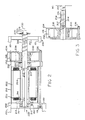
- Figure 2 is an axial cross-sectional illustration of a salient pole motor including a stationary assembly for attachment to the vehicle, the stationary assembly coupled to a rotatable assembly having a threaded shaft driving a nut on the wheel assembly.
- Figure 3 is a partial axial cross-sectional illustration of the motor of Figure 2 including a stationary assembly for attachment to the vehicle, the stationary assembly coupled to a rotational assembly having an internally threaded shaft driving a threaded shaft on the wheel assembly.
- Figure 4 is a block diagram of another preferred embodiment of a suspension system of the invention including a hydraulic pump on the vehicle frame driving a ram on the wheel assembly.
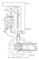
- Figure 5 is a transverse cross-sectional illustration of a six coil, four pole motor of the invention.
- Figures 6, 7 and 8 are graphs of motor speed in thousands of revolutions per minute along the ordinate and motor torque in ounce-feet along the abscissa of the dynamic suspension actuator performance according to the invention including an electronically commutated motor (ECM) energized at 96V dc power and controlled by a pulse width modulating signal at 20KHz.
- the demagnetizing current for the salient pole motor equals 585 amperes at -40°C, 427 amperes at 25°C and 184 amperes at 125°C.
- Figures 9 and 10 are graphs of ram force in pounds along the ordinate and motor speed in thousands of revolutions per minute along the abscissa of the force offset of electronically commutated motors having ball screws with 20mm and 25mm pitches, respectively, for use as part of a dynamic suspension system of the invention.
- the solid lines illustrate motor hysteresis and eddy current losses and the dashed lines illustrate ball screw efficiency.
- a vehicle frame 100 is supported for travel over a surface 102 of terrain by a wheel assembly 110 in contact with the surface 102.
- a spring 105 or other resilient support interconnects the vehicle frame 100 and the wheel assembly 110 along axis 106 to establish a no-force equilibrium position between the vehicle frame 100 and the wheel assembly in which the vehicle is supported in a predetermined position with respect to the surface 102 of the terrain.
- the predetermined position is, preferably, the position that the vehicle frame 100 assumes with respect to the wheel assembly 110 with no external force applied to either other than the compression forces of spring 105.
- a dynamoelectric machine such as a switch reluctance motor, an electronically commutated motor or other motor referred to by reference character 120 is mounted on the vehicle frame 100 to rotate a drive shaft 130.
- the shaft 130 is connected to a rotary to linear motor translator 140 which is on wheel assembly 110 and moves member 150 on wheel assembly 110 linearly with respect to vehicle frame 100. Therefore, the wheel assembly 110 supports the vehicle frame 100 by connection through member 150, translator 140, shaft 130 and motor 120 mounted on the vehicle frame 100.
- the wheel assembly 110 may also be connected to the vehicle frame 100 directly, such as by hinged member 114 shown in phantom.
- Motor 120 includes a stationary assembly 122 magnetically coupled to a rotatable assembly 124 and having a plurality of winding stages (see Figure 5A) adapted to be electrically energized to apply an electromagnetic field to the rotatable assembly 124 thereby to rotatably drive it in either direction.
- Motor 120 may also be a switched reluctance motor.
- the rotatable assembly 124 is coaxially connected to the drive shaft 130 along axis 152. Therefore, translator 140 constitutes means, interconnecting the rotatable assembly 124 and the wheel assembly 110, for linearly changing the relative position thereof along axis 152 in response to rotational motion of the rotatable assembly 124 caused by the stationary assembly 122.
- translator 140 is constructed and arranged to relatively move the vehicle frame 100 and the wheel assembly 110 along axis 152 coaxial with axis 126 of rotation of rotatable assembly 124 and parallel to axis 106 of the spring 105.
- the system includes a sensor 102 on the vehicle frame 100, a load cell or other sensor 103 between motor 120 and frame 100, and/or accelerometer 112 on the wheel assembly 110 for sensing a parameter which is a function of the position and/or movement of the vehicle frame 100 and the wheel assembly 110.
- the sensors may be velocity sensors, acceleration sensors, horizontal position sensors, vertical position sensors, sensors which detect the relative position between the vehicle frame 100 and wheel assembly 110, inertial detectors, centrifugal force detectors, load sensors or any other type of position or movement sensor or combination thereof.
- sensors 102 and 112 may be coils or other electromagnetically linked components which are sensitive to movement with respect to each other thereby permitting either sensor to detect its position relative to the other.
- the sensors 102 and 112 provide signals to a microprocessor 160. If the sensor output signals are analog signals, the microprocessor 160 converts these signals to digital form. If the sensor output signals are digital, no conversion is necessary.
- Microprocessor 160 provides logic level system electronics and may also be supplied with a vehicle velocity signal and a speed and position signal provided by shaft encoder 132. The microprocessor 160 evaluates these digital signals to determine whether deviation from the equilibrium position of the vehicle frame 100 has occurred and whether any change in the relative position between the vehicle frame 100 and the vehicle assembly 110 is necessary or desirable.
- sensors 102 and 112 may be infrared range sensors for detecting the horizontal position of the vehicle frame 100 and the wheel assembly 110, respectively, with respect to the road surface.
- Microprocessor 160 may be programmed to maintain the vehicle frame 110 level within certain horizontal position limits with respect to the surface 102 of the terrain. Any change in the horizontal position of the vehicle frame 100 and wheel assembly 120 would be detected by the sensors and transmitted to microprocessor 160. Such a change may be caused by the wheel assembly 110 coming in contact with a hole or rise in the surface 102. Microprocessor 160 would in turn energize a commutation circuit 170 via line 162 to supply power to the motor 120 provided by a power supply 180. Microprocessor 160 would continue to control commutation circuit 170 to energize motor 120 to maintain the vehicle frame 110 within the horizontal limits.
- the commutation circuit 170 may be any standard commutation circuit known in the prior art, such as disclosed in U.S. patent No.
- microprocessor 160 would be programmed to provide a pulse width modulated (PWM) signal as a speed command via line 162 having a duty cycle representative of the desired speed or torque of motor 120.
- PWM pulse width modulated
- the sensors 102 and 112 and the microprocessor 160 constitute means for detecting changes in the sensed parameters as detected by the sensors.
- the motor 120 is preferably powered by a power supply 180 such as a three-phase rectified alternator driven by the vehicle engine.
- the power supply 180 and the commutation circuit 170 constitute means for energizing the winding stages as a function of changes in the parameters detected by the detecting means.
- the commutation circuit 170, microprocessor 160 and sensor constitute means for energizing the winding stages as a function of deviation from the equilibrium position so that the vehicle is substantially supported in the predetermined position as the vehicle travels over the surface of the terrain.
- the microprocessor 160 may also control an array of switches 190 for controlling the mode of opertion of the motor 120.
- the motor 120 have three modes of operation: active, inactive and regenerative.
- the active mode as described above, the commutation circuit 170 is connected to the winding stages. This allows energizing of the winding stages in accordance with control signals provided by the microprocessor 160 via line 162.
- the inactive mode the winding stages are short-circuited to produce a retarding torque.
- Linear motion of the wheel assembly 110 with respect to the vehicle 100 is converted by translator 140 into rotary motion with rotates the rotatable assembly 124 of the motor 120.
- the suspension system functions like a shock absorber resisting but permitting movement of the wheel assembly 110 with respect to the vehicle 100. If the winding stages are not short-circuited, rotation of the rotatable assembly 124 caused by linear motion of the wheel assembly 110 with respect to the vehicle 100 induces an emf in the winding stages. In the regenerative mode, the induced emf is stored for later use.
- the switches 190 are controlled by the microprocessor 160 via line 192.
- the switches 190 are positioned to directly electrically connect the commutation circuit 170 to the winding stages of the motor 120.
- the switches 190 are positioned to short-circuit the winding stages of the motor 120.
- the inactive mode may also be used when a diagnostic signal provided via line 164 indicates that the system is not operating properly.
- the switches 190 connect the commutation circuit 170 and the winding stages and the commutation circuit is controlled to directly electrically connect the winding stages of the motor 120 to a capacitor filter bank 194.
- the microprocessor 160 also controls commutation circuit 170 which selects the power source for energizing the motor windings. Power may be supplied to the commutation circuit 170 by the power supply 180 or by the capacitor filter bank 194.
- the microprocessor 160 may monitor the line current or voltage of the capacitor filter bank 194 or the power supply 180 via shunt line 197, the phase currents via line 198, or the rotor position via line 199.
- the microprocessor 160 may also control a switch, not shown, for grounding the capacitor filter bank 194.
- spring 105 maintains the relative position of the vehicle frame 100 and the wheel assembly 110 in a no-force equilibrium position.
- the wheel assembly 110 encounters a hole in the road surface, the wheel assembly begins to fall into the hole and its downward vertical movement is detected by one or more sensors such as position sensor 112.
- the vehicle frame 100 will indirectly follow the wheel assembly 110 and also begin to move downward as detected by sensor 107. This will generate a force applied to the load cell 103 and indicated to the microprocessor 160.
- Microprocessor 160 evaluates the signals generated by the sensors and, in response thereto, provides a signal via line 162 to control the commutation circuit 170 to energize motor 120 to rotate shaft 130.
- Translator 140 converts the rotation of shaft 130 into linear motion to move support member 150 downward to maintain the vehicle frame 100 in a level position.
- FIG. 2 illustrates one preferred embodiment of a motor 200 and a translator 201 according to the invention for connection between the vehicle frame 100 and the wheel assembly 110.
- the motor 200 comprises a stationary assembly including a core 202 having a plurality of winding stages thereon.
- the motor 200 also includes a rotatable assembly including a plurality of permanent magnet elements 204 peripherally spaced on a shaft 205.
- the shaft 205 extends out beyond the core 202 and terminates in a threaded end 206 engaged by a traveling nut 207 welded to the wheel assembly 110.
- the motor 200 includes end plates 208, 209 between which a cylindrical housing 210 is positioned for supporting the stationary assembly.
- the end plate 208 includes a bearing 211 within which the unthreaded end of shaft 205 is journaled for rotation.
- a spacer 212 may be provided to maintain the position of the shaft 205 within the bearing 211.
- End cap 208 may be provided with switch bracket 213 affixed to cap 208 by screw 214 for supporting Hall sensors 214 for detecting the position of the shaft 205.
- the position of shaft 205 may be determined by detecting the back electromotive force (emf) of the winding stages 203.
- End cap 209 is also provided with a bearing 215 within which the central portion of shaft 205 is journaled for rotation.
- the center of the shaft may also be provided with a retaining ring 216 and rivet 217 for maintaining the position of the shaft within the housing of the motor.
- End shield 209 supports end cap 218 within which the commutation circuitry may be located.
- a plurality of circumferentially spaced pins 232 interconnect cap 218 and retaining plate 234.
- a plurality of circumferentially spaced bolts 236 connect end plate 208 and retaining plate 234.
- Frame 100 may be welded to the stationary assembly of motor 200 or otherwise affixed thereto, such as by mounting end plate 208 to flange 101 via bolt 236.
- Shaft adapter 238 is positioned between retaining plate 234 and the base of end cap 218 to support shaft 205 and is held in place by key 240.
- Shaft 205 terminates in a reduced diameter section 219 having a disc spring 220 held in place by retaining ring 221 to prevent the traveling nut 207 from disengaging the shaft 205.
- the winding stages 202 are selectively energized by the commutation circuit 170 to rotate shaft 205 in either direction.
- the threaded engagement between the nut 207 and the threads of shaft 205 drive the nut 207 linearly along the shaft 205 to change the relative position of the motor and the nut 207.
- the vehicle frame 100 attached to the motor 200 and the wheel assembly 110 attached to the nut 207 linearly change their relative positions as well.
- FIG 3 illustrates an alternative embodiment of the motor and translator combination.
- shaft 205 terminates in an end 301 having internally threaded bore 302 which is engaged by a threaded shaft 304 on the wheel assembly.
- Shaft 304 is fixed into wheel assembly 201 to prevent axial rotation. Rotation of shaft 205 results in a linear change along axis 230 in the relative postion between shaft 205 and the shaft 304. Consequently, the relative position between the vehicle frame and the wheel assembly is also changed.
- the stationary assembly of the motor 200 is fixed to the vehicle fame 100 and the threaded end 206 forms a screw which is an extension of the motor shaft 205.
- the nut 207 is fixed to the wheel assembly 110 and does not rotate.
- the screw rotates along with the motor, thus moving the nut 207 and the wheel assembly axially along axis of rotation 230.
- the stationary assembly of the motor 200 is fixed to the vehicle from 100 and the end 301 of the shaft 205 forms a nut which is an extension of the motor shaft 205.
- the screw is formed by shaft 304 which is fixed to the wheel assembly 100 and does not rotate.
- the nut rotates along with the motor, thus, moving the screw and the wheel assembly axially along axis of rotation 230.
- the bore 304 is only partially engaged by the shaft 304 to permit the shaft 304 to move along the axis 230 in either direction.
- Table I summarizes the constraints for a round electronically commutated motor for use as a dynamic suspension actuator according to the invention.
- the motor constraints are those dictated by the particular translator configuration.
- a threaded shaft engaging a traveling nut i.e., the ball screw structure
- its mechanical limitations will determine the preferred configuration.
- Motor speeds and torques for four different ball screw pitches are listed in Table I.
- Currently available ball screws have maximum rated speeds of 10,000 rpms. This necessarily dictates an upper limit in that the ball screw pitch cannot be less than nominally 20 millimeters.
- the pitch in centimeters, is defined as the distance the ball travels as a result of one rotation of the screw, or the distance between adjacent threads on the screw, i.e., Another motor constraint is the motor size.
- motors and rotatable assemblies therefor become physically too large to operate at speeds substantially below 7200 rpms, which requires high torques.
- This constraint eliminates motors having ball screw pitches substantially greater than 25 millimeters. Therefore, it has been found that the round electronically commutated motor constraints result in the use of a motor confined to the two sets of speeds and torques associated with the ball screws having pitches within the range or 20-25 mm.
- Table II summarizes the round electronically commutated motor specifications for a dynamic suspension actuator according to the invention for both the 20 millimeter and 25 millimeter ball screw pitches.
- the motor specifications of Table II relate to a salient pole motor having six coils, one on each tooth T of the stationary assembly 500, and four poles P on the rotational assembly 510 as illustrated in Figure 5.
- the Table II specifications also assume that the motor will be operated according to a three-phase, full bridge commutation circuit and that 96 volts of DC power will be provided by the power supply.
- Both the 20 millimeter ball screw pitch motor and the 25 millimeter ball screw pitch motor are essentially identical except for stack length as shown in Table II.
- the motor associated with the 20 millimeter ball screw pitch has a shorter stack length and a shorter rotor length.
- a salient pole construction was selected to alleviate end turn problems which can be particularly difficult for conventionally wound motors of this kind.
- High energy NdFeB magnets are used as the permanent magnet elements of the rotors of each of the motors to meet the commutation, saturation, demagnetizing and heat constraints of the motor.
- an alternative electrohydrostatic actuator is illustrated in block diagram form.
- a hydraulic pump 402 on vehicle frame 404 is driven by motor 405 to translate the rotary motion of the rotatable assembly 406 into linear motion.
- stationary assembly 408 on vehicle frame 404 drives the rotary assembly 406 to power hydraulic pump 402 and drive piston/ram 410 on wheel assembly 412. This linearly moves the piston/ram 410 thereby changing the relative position of the wheel assembly 412 with respect to the vehicle frame 404.
- the hydraulic pump is a multi-piston, positive displacement type with approximately 0.09 cubic inches of total displacement. Such a pump responds instantaneously with the high pressure needed to move the ram piston and requires no reservoir of fluid.
- Rotatable assembly 406 may be rotatably driven by the stationary assembly 408 in either direction. Driving rotatable assembly 406 in one direction results in pump 402 pumping fluid from upper chamber 414, via line 416 acting as a pump inlet line, via line 418 acting as a pump outlet line, and into lower chamber 420 to drive the piston/ram upward.
- driving rotatable assembly 406 in the other direction results in pump 402 pumping fluid from lower chamber 420, via line 418 acting as a pump inlet line, via line 416 acting as a pump outlet and into upper chamber 414 to drive the piston/ram downward.
- the hydraulic pump 402 and motor 405 would be sized to meet the force and speed requirements of the dynamic suspension system according to the invention.
- a resilient member 420 may interconnect vehicle 404 and wheel assembly 412 along axis 422, parallel to axis 424 of the EHA, to establish a no force, equilibrium position.
- the motor must have servo quality.
- the motor must operate in all four quadrants and respond to position feedback signals.
- the rotor inertia should be small, in the order of 10% of the reflected load inertia. It is also contemplated that regeneration energy can be dissipated as heat or stored in the capacitor filter bank, as shown in Figure 1.
- the rotor outside diameter is limited to 1.10 inches maximum by the inertia requirements. It is believed that the outside diameter of the rotor cannot be significantly greater than 1.10 inches because of winding difficulties with the stator.
- the stator inside diameter can be larger and its outside diameter can remain within the 4" outside diameter space limitations if larger slots for larger wire sizes are needed to reduce copper losses.
- Figures 6 and 7 illustrate computer simulations of speed/torque performance for two motors having ball screws with pitches of 20 mm. and 25 mm., respectively, for operating temperatures in the range of -40°C. to 125°C.
- An 80° electrical flat top of a back emf waveform and a 15° advance commutation angle are assumed.
- a 15° advance requires two sets of shaft position sensors, one for forward and one for reverse. Simulations for a 30° advance, for which just one position sensor set would be needed, suggests modest reductions but acceptable performance.
- Figure 8 is similar to Figure 7 and illustrates motor performance for slightly different parameters for the 25 millimeter ball screw pitch.
- This retarding torque forms a mode of operation which can be activated in case of a system failure to permit the suspension system to operate as a shock absorber or dynamic brake to buffer relative motion between the vehicle and its wheels caused by bumps or holes in the road surface.
- This mode permits the vehicle to continue operation until a repair can be made.
Landscapes
- Engineering & Computer Science (AREA)
- Mechanical Engineering (AREA)
- Power Engineering (AREA)
- Vehicle Body Suspensions (AREA)
- Control Of Position Or Direction (AREA)
Applications Claiming Priority (2)
| Application Number | Priority Date | Filing Date | Title |
|---|---|---|---|
| US461736 | 1990-01-08 | ||
| US07/461,736 US5028073A (en) | 1990-01-08 | 1990-01-08 | Dynamic vehicle suspension system including electronically commutated motor |
Publications (2)
| Publication Number | Publication Date |
|---|---|
| EP0436870A2 true EP0436870A2 (fr) | 1991-07-17 |
| EP0436870A3 EP0436870A3 (en) | 1992-04-01 |
Family
ID=23833745
Family Applications (1)
| Application Number | Title | Priority Date | Filing Date |
|---|---|---|---|
| EP19900124309 Ceased EP0436870A3 (en) | 1990-01-08 | 1990-12-15 | Dynamic vehicle suspension system including electronically commutated motor |
Country Status (5)
| Country | Link |
|---|---|
| US (1) | US5028073A (fr) |
| EP (1) | EP0436870A3 (fr) |
| JP (1) | JPH04252718A (fr) |
| KR (1) | KR910014247A (fr) |
| IT (1) | IT1244517B (fr) |
Cited By (14)
| Publication number | Priority date | Publication date | Assignee | Title |
|---|---|---|---|---|
| EP0495565A3 (en) * | 1991-01-14 | 1992-12-02 | Ford Motor Company Limited | Fail-safe variable damping suspension for a motor vehicle |
| WO1995016253A1 (fr) * | 1993-12-09 | 1995-06-15 | Denne Developments Limited | Systemes de commande de mouvements |
| EP0878333A1 (fr) * | 1997-05-16 | 1998-11-18 | Conception et Développement Michelin | Dispositif de suspension comportant un correcteur de ressort |
| DE10060536A1 (de) * | 2000-12-06 | 2002-06-13 | Bayerische Motoren Werke Ag | Verfahren zur Steuerung des Fahrwerksystems eines zweispurigen Kraftfahrzeuges sowie entsprechendes Kraftfahrzeug |
| EP1681188A1 (fr) * | 2005-01-14 | 2006-07-19 | Zf Friedrichshafen Ag | Procédé de fonctionnement d'un support de ressort à régulation électrique de la force du ressort |
| EP1512559A3 (fr) * | 2003-09-08 | 2006-08-09 | Bose Corporation | Suspension active pour véhicule avec système de sûreté |
| EP1681187A3 (fr) * | 2005-01-14 | 2008-07-23 | Zf Friedrichshafen Ag | Actionneur pour une coupelle de ressort réglable |
| US7962261B2 (en) | 2007-11-12 | 2011-06-14 | Bose Corporation | Vehicle suspension |
| US7983813B2 (en) | 2004-10-29 | 2011-07-19 | Bose Corporation | Active suspending |
| US8095268B2 (en) | 2004-10-29 | 2012-01-10 | Bose Corporation | Active suspending |
| EP2364866A4 (fr) * | 2008-12-01 | 2012-10-17 | Toyota Motor Co Ltd | Système de suspension électromagnétique |
| DE102012008497A1 (de) * | 2012-04-18 | 2013-10-24 | Audi Ag | Steuereinrichtung für ein Motorlager mit elektromagnetischer Aktorik |
| WO2014055639A1 (fr) * | 2012-10-03 | 2014-04-10 | Bose Corporation | Système de suspension active |
| WO2016058761A1 (fr) * | 2014-10-14 | 2016-04-21 | Zf Friedrichshafen Ag | Amortisseur de vibrations et véhicule automobile |
Families Citing this family (52)
| Publication number | Priority date | Publication date | Assignee | Title |
|---|---|---|---|---|
| US5187398A (en) * | 1988-08-31 | 1993-02-16 | Aura Systems, Inc. | Electromagnetic actuator |
| JPH033692A (ja) * | 1989-05-29 | 1991-01-09 | Secoh Giken Inc | 負荷の数値制御装置 |
| KR940007210B1 (ko) * | 1989-11-29 | 1994-08-10 | 미쯔비시 덴끼 가부시끼가이샤 | 자동차용 현가장치 |
| US5296785A (en) * | 1991-12-23 | 1994-03-22 | Ford Motor Company | Fail-safe vehicle suspension system including switched reluctance motor |
| EP0549114B1 (fr) * | 1991-12-23 | 1997-03-19 | Ford Motor Company Limited | Suspension avec un système de sécurité pour véhicule |
| US5350983A (en) * | 1992-12-21 | 1994-09-27 | Ford Motor Company | Suspension damper with integrated controls |
| US5583844A (en) * | 1993-06-19 | 1996-12-10 | The Walt Disney Company | Programming device and method for controlling ride vehicles in an amusement attraction |
| US5473990A (en) * | 1993-08-19 | 1995-12-12 | The Walt Disney Company | Ride vehicle control system |
| EP0670745B1 (fr) | 1993-08-19 | 1998-10-07 | The Walt Disney Company | Vehicule dynamique pour manege |
| US5403238A (en) * | 1993-08-19 | 1995-04-04 | The Walt Disney Company | Amusement park attraction |
| DE69432192T2 (de) | 1993-10-12 | 2003-12-04 | Smc K.K., Tokio/Tokyo | Linearantrieb |
| US5441298A (en) * | 1993-10-22 | 1995-08-15 | Ford Motor Company | Apparatus for stabilizing an electric active suspension system upon interruption of the power supply |
| US5523637A (en) * | 1994-04-28 | 1996-06-04 | Ford Motor Company | Permanent magnet electrical machine with low reluctance torque |
| US5831360A (en) * | 1995-12-15 | 1998-11-03 | Iai Corporation | Actuator |
| US6270414B2 (en) * | 1997-12-31 | 2001-08-07 | U.S. Philips Corporation | Exoskeletal platform for controlling multi-directional avatar kinetics in a virtual environment |
| ATE283772T1 (de) | 2000-10-11 | 2004-12-15 | Conception & Dev Michelin Sa | Aufhängungssystem mit einer niveauregeleinrichtung |
| FR2814985A1 (fr) | 2000-10-11 | 2002-04-12 | Conception & Dev Michelin Sa | Dispositif de suspension comportant un verin electrique et un ressort en parallele |
| EP1271752A1 (fr) * | 2001-06-13 | 2003-01-02 | HSU, Chun-Pu | Dispositif permettant d'augmenter la vitesse de rotation d'un moteur à aimants permanents |
| TWI266386B (en) * | 2001-10-03 | 2006-11-11 | Hannstar Display Corp | Dual vertical cannel thin film transistor for SRAM and manufacturing method thereof |
| EP1510721B1 (fr) * | 2002-06-06 | 2010-06-30 | Kayaba Industry Co., Ltd. | Amortisseur electromagnetique |
| US20050230201A1 (en) * | 2004-04-16 | 2005-10-20 | Takuhiro Kondou | Electromagnetic shock absorber for vehicle |
| US6945541B2 (en) * | 2003-01-21 | 2005-09-20 | Bose Corporation | Vehicle suspension |
| US6920951B2 (en) | 2003-04-17 | 2005-07-26 | Visteon Global Technologies, Inc. | Regenerative damping method and apparatus |
| US6926288B2 (en) * | 2003-06-02 | 2005-08-09 | Bose Corporation | Electromagnetic interference filter |
| JP4438406B2 (ja) * | 2003-06-27 | 2010-03-24 | アイシン精機株式会社 | スタビライザ制御装置 |
| DE102005026047A1 (de) * | 2005-06-03 | 2006-12-14 | Benteler Automobiltechnik Gmbh | Radführung |
| JP2007216822A (ja) * | 2006-02-16 | 2007-08-30 | Kayaba Ind Co Ltd | 電磁サスペンション装置 |
| US8839920B2 (en) | 2008-04-17 | 2014-09-23 | Levant Power Corporation | Hydraulic energy transfer |
| US10279641B2 (en) | 2008-04-17 | 2019-05-07 | ClearMotion, Inc. | Distributed active suspension with an electrically driven pump and valve controlled hydraulic pump bypass flow path |
| DE102008033820B4 (de) * | 2008-07-19 | 2015-06-25 | Audi Ag | Kraftfahrzeug mit aktiver Federung |
| EP4289640B1 (fr) | 2010-06-16 | 2025-11-05 | ClearMotion, Inc. | Amortisseur de génération d'énergie intégré |
| US8878468B2 (en) * | 2011-04-29 | 2014-11-04 | Pratt & Whitney Canada Corp. | Electric machine assembly with fail-safe arrangement |
| US9174508B2 (en) | 2013-03-15 | 2015-11-03 | Levant Power Corporation | Active vehicle suspension |
| US8840118B1 (en) | 2013-03-15 | 2014-09-23 | Levant Power Corporation | Active suspension with on-demand energy flow |
| WO2014176371A2 (fr) | 2013-04-23 | 2014-10-30 | Levant Power Corporation | Suspension active dotée d'un actionneur structurel |
| US11635075B1 (en) | 2014-06-25 | 2023-04-25 | ClearMotion, Inc. | Gerotor pump with bearing |
| US9624998B2 (en) * | 2014-07-30 | 2017-04-18 | Tenneco Automotive Operating Company Inc. | Electromagnetic flywheel damper and method therefor |
| US10851816B1 (en) | 2014-08-19 | 2020-12-01 | ClearMotion, Inc. | Apparatus and method for active vehicle suspension |
| DE102014221699A1 (de) * | 2014-10-24 | 2016-04-28 | Suspa Gmbh | Vorrichtung zum Höhenverstellen eines ersten Teils gegenüber einem zweiten Teil, Nachrüstsatz für eine derartige Vorrichtung sowie höhenverstellbares System umfassend mehrere derartige Vorrichtungen |
| EP3247577B1 (fr) | 2015-01-23 | 2020-03-04 | Clearmotion, Inc. | Procédé et appareil de commande d'un actionneur |
| US9906094B2 (en) * | 2015-03-20 | 2018-02-27 | American Axle & Manufacturing, Inc. | Direct drive actuator with switched reluctance motor |
| JP2017051032A (ja) * | 2015-09-03 | 2017-03-09 | アスモ株式会社 | 回転電機 |
| JP6956722B2 (ja) | 2015-12-24 | 2021-11-02 | クリアモーション,インコーポレイテッド | 統合多重アクチュエータ電子油圧ユニット |
| EP3580075A4 (fr) | 2017-02-12 | 2021-01-20 | Clearmotion, Inc. | Actionneur hydraulique à rapport de pression relative dépendant de la fréquence |
| US11892051B2 (en) | 2018-02-27 | 2024-02-06 | ClearMotion, Inc. | Through tube active suspension actuator |
| US10619735B2 (en) * | 2018-04-27 | 2020-04-14 | GM Global Technology Operations LLC | Systems for hydraulic energy delivery |
| US11511589B2 (en) * | 2018-08-20 | 2022-11-29 | Rassini Suspensiones, S.A. De C.V. | Adjustable suspension mount assembly |
| CN113661108B (zh) | 2019-04-05 | 2024-07-05 | 沃尔沃卡车集团 | 用于确定指示支撑车辆的路段的道路能力的参数的方法和控制单元 |
| JP6840185B2 (ja) * | 2019-04-16 | 2021-03-10 | 本田技研工業株式会社 | 電動サスペンション装置 |
| US12054022B2 (en) * | 2020-09-14 | 2024-08-06 | Lg Electronics Inc. | Robot |
| US12594807B2 (en) * | 2021-10-18 | 2026-04-07 | Jaguar Land Rover Limited | Functional safety protection mechanism self-test |
| CN120963274A (zh) * | 2024-05-13 | 2025-11-18 | 汉拿万都株式会社 | 车辆高度调节装置 |
Family Cites Families (15)
| Publication number | Priority date | Publication date | Assignee | Title |
|---|---|---|---|---|
| GB1096497A (en) * | 1965-12-15 | 1967-12-29 | Moulton Development Ltd | Improvements in vehicle wheel suspension systems |
| DE2336078A1 (de) * | 1973-07-16 | 1975-02-06 | Reiner Joachim Merkel | Induktiver stosswandler |
| US4500821A (en) * | 1983-06-09 | 1985-02-19 | General Electric Company | Speed or torque control circuit for an electronically commutated motor (ECM) and method of controlling the torque or speed of an ECM |
| US4555120A (en) * | 1983-10-07 | 1985-11-26 | Kelsey-Hayes Co. | Position sensor |
| DE3522221A1 (de) * | 1984-06-27 | 1986-02-27 | Volkswagen AG, 3180 Wolfsburg | Schwingungsdaempferanordnung fuer ein fahrzeug mit einem elektrodynamischen drehschwingungsdaempfer |
| JPH0789728B2 (ja) * | 1985-04-30 | 1995-09-27 | 三菱化学株式会社 | モ−タ |
| DE3641480A1 (de) * | 1986-12-04 | 1988-06-16 | Zinser Textilmaschinen Gmbh | Vorrichtung zur hoehenregulierung eines bedienlaeufers an einer spinnereimaschine |
| DE3644429A1 (de) * | 1986-12-24 | 1988-09-01 | Bochumer Eisen Heintzmann | Elektrohydraulischer stellzylinder |
| IT210468Z2 (it) * | 1987-01-21 | 1988-12-30 | Iveco Fiat | Attuatore lineare elettromeccanico per il ribaltamento della cabina di guida di un veicolo industriale |
| DE3734287A1 (de) * | 1987-10-09 | 1989-04-27 | Manfred Dipl Ing Kessler | Fahrzeugfahr- bzw. -laufwerk |
| US4815575A (en) * | 1988-04-04 | 1989-03-28 | General Motors Corporation | Electric, variable damping vehicle suspension |
| US4892328A (en) * | 1988-05-27 | 1990-01-09 | Aura Systems, Inc. | Electromagnetic strut assembly |
| US4912343A (en) * | 1988-08-31 | 1990-03-27 | Aura Systems, Inc. | Electromagnetic actuator |
| CA1336616C (fr) * | 1988-10-05 | 1995-08-08 | I. Davis Roy | Suspension active electrique pour vehicule |
| US4859974A (en) * | 1988-10-11 | 1989-08-22 | General Electric Company | Electromagnetic motor/actuator |
-
1990
- 1990-01-08 US US07/461,736 patent/US5028073A/en not_active Expired - Lifetime
- 1990-12-15 EP EP19900124309 patent/EP0436870A3/en not_active Ceased
- 1990-12-28 KR KR1019900022220A patent/KR910014247A/ko not_active Ceased
-
1991
- 1991-01-08 JP JP3018214A patent/JPH04252718A/ja not_active Withdrawn
- 1991-01-08 IT ITMI910022A patent/IT1244517B/it active IP Right Grant
Cited By (17)
| Publication number | Priority date | Publication date | Assignee | Title |
|---|---|---|---|---|
| EP0495565A3 (en) * | 1991-01-14 | 1992-12-02 | Ford Motor Company Limited | Fail-safe variable damping suspension for a motor vehicle |
| WO1995016253A1 (fr) * | 1993-12-09 | 1995-06-15 | Denne Developments Limited | Systemes de commande de mouvements |
| EP0878333A1 (fr) * | 1997-05-16 | 1998-11-18 | Conception et Développement Michelin | Dispositif de suspension comportant un correcteur de ressort |
| US6161844A (en) * | 1997-05-16 | 2000-12-19 | Conception Et Developpement Michelin S.A. | Suspension device comprising a spring corrector |
| DE10060536A1 (de) * | 2000-12-06 | 2002-06-13 | Bayerische Motoren Werke Ag | Verfahren zur Steuerung des Fahrwerksystems eines zweispurigen Kraftfahrzeuges sowie entsprechendes Kraftfahrzeug |
| EP1512559A3 (fr) * | 2003-09-08 | 2006-08-09 | Bose Corporation | Suspension active pour véhicule avec système de sûreté |
| US8548678B2 (en) | 2004-10-29 | 2013-10-01 | Bose Corporation | Active suspending |
| US7983813B2 (en) | 2004-10-29 | 2011-07-19 | Bose Corporation | Active suspending |
| US8095268B2 (en) | 2004-10-29 | 2012-01-10 | Bose Corporation | Active suspending |
| EP1681187A3 (fr) * | 2005-01-14 | 2008-07-23 | Zf Friedrichshafen Ag | Actionneur pour une coupelle de ressort réglable |
| EP1681188A1 (fr) * | 2005-01-14 | 2006-07-19 | Zf Friedrichshafen Ag | Procédé de fonctionnement d'un support de ressort à régulation électrique de la force du ressort |
| US7962261B2 (en) | 2007-11-12 | 2011-06-14 | Bose Corporation | Vehicle suspension |
| EP2364866A4 (fr) * | 2008-12-01 | 2012-10-17 | Toyota Motor Co Ltd | Système de suspension électromagnétique |
| DE102012008497A1 (de) * | 2012-04-18 | 2013-10-24 | Audi Ag | Steuereinrichtung für ein Motorlager mit elektromagnetischer Aktorik |
| WO2014055639A1 (fr) * | 2012-10-03 | 2014-04-10 | Bose Corporation | Système de suspension active |
| WO2016058761A1 (fr) * | 2014-10-14 | 2016-04-21 | Zf Friedrichshafen Ag | Amortisseur de vibrations et véhicule automobile |
| US10245913B2 (en) | 2014-10-14 | 2019-04-02 | Zf Friedrichshafen Ag | Vibration damper and motor vehicle |
Also Published As
| Publication number | Publication date |
|---|---|
| ITMI910022A1 (it) | 1992-07-08 |
| US5028073A (en) | 1991-07-02 |
| ITMI910022A0 (it) | 1991-01-08 |
| KR910014247A (ko) | 1991-08-31 |
| IT1244517B (it) | 1994-07-15 |
| JPH04252718A (ja) | 1992-09-08 |
| EP0436870A3 (en) | 1992-04-01 |
Similar Documents
| Publication | Publication Date | Title |
|---|---|---|
| US5028073A (en) | Dynamic vehicle suspension system including electronically commutated motor | |
| CN104552329B (zh) | 驱动控制一体化智能集成关节 | |
| US5149998A (en) | Eddy current drive dynamic braking system for heat reduction | |
| CN100355188C (zh) | 单相电机 | |
| US20020166716A1 (en) | Electric power steering apparatus | |
| CN106826906B (zh) | 一种无力矩传感器的机械臂模块化关节 | |
| JP2013046440A (ja) | 回転電機 | |
| CN117811263A (zh) | 一种双余度电机双旋变结构 | |
| JP2003223220A (ja) | 電磁サスペンション装置 | |
| US5682089A (en) | Control circuit for generating a speed dependent deceleration force in an electronically commutated motor | |
| US20230253846A1 (en) | Fault tolerant redundant electric motor | |
| CN118891809A (zh) | 运行用于轮子的电磁式发电机的方法和用于轮子的发电机 | |
| CN110880828A (zh) | 一种能够监测转速和补偿输出的力矩电机 | |
| CN210669691U (zh) | 一种可监测转速的力矩电机 | |
| CN105946590A (zh) | 一种全轮独立驱动有感无刷电动车制动的装置及方法 | |
| CN215378696U (zh) | 一种带有刹车功能的沙发驱动装置 | |
| CN1226861A (zh) | 轮毂中的能量转换系统 | |
| CN216794786U (zh) | 一种内置刹车结构的交流伺服电机 | |
| CN2683678Y (zh) | 缝纫机用无刷直流电机驱动控制器 | |
| CN217789580U (zh) | 一种步进电机组合装置 | |
| CN115149713A (zh) | 一种大推力的直接丝杆输出伺服电缸 | |
| CN211139449U (zh) | 伺服转向系统及车辆 | |
| JP3927747B2 (ja) | 回転体上電気装置用制御装置 | |
| CN212785037U (zh) | 一种精密点焊系统伺服电机 | |
| CN210577986U (zh) | 一种伺服电机 |
Legal Events
| Date | Code | Title | Description |
|---|---|---|---|
| PUAI | Public reference made under article 153(3) epc to a published international application that has entered the european phase |
Free format text: ORIGINAL CODE: 0009012 |
|
| AK | Designated contracting states |
Kind code of ref document: A2 Designated state(s): DE FR GB |
|
| PUAL | Search report despatched |
Free format text: ORIGINAL CODE: 0009013 |
|
| AK | Designated contracting states |
Kind code of ref document: A3 Designated state(s): DE FR GB |
|
| 17P | Request for examination filed |
Effective date: 19920930 |
|
| 17Q | First examination report despatched |
Effective date: 19940601 |
|
| GRAG | Despatch of communication of intention to grant |
Free format text: ORIGINAL CODE: EPIDOS AGRA |
|
| STAA | Information on the status of an ep patent application or granted ep patent |
Free format text: STATUS: THE APPLICATION HAS BEEN REFUSED |
|
| 18R | Application refused |
Effective date: 19960915 |