EP0436933A2 - Vorrichtung und Verfahren zum Wiederherstellen von Turbinenschaufeln - Google Patents
Vorrichtung und Verfahren zum Wiederherstellen von Turbinenschaufeln Download PDFInfo
- Publication number
- EP0436933A2 EP0436933A2 EP90125557A EP90125557A EP0436933A2 EP 0436933 A2 EP0436933 A2 EP 0436933A2 EP 90125557 A EP90125557 A EP 90125557A EP 90125557 A EP90125557 A EP 90125557A EP 0436933 A2 EP0436933 A2 EP 0436933A2
- Authority
- EP
- European Patent Office
- Prior art keywords
- blade
- movement
- machine
- machining
- turbine blade
- Prior art date
- Legal status (The legal status is an assumption and is not a legal conclusion. Google has not performed a legal analysis and makes no representation as to the accuracy of the status listed.)
- Granted
Links
- 238000000034 method Methods 0.000 title claims abstract description 22
- 230000008439 repair process Effects 0.000 title description 11
- 238000003754 machining Methods 0.000 claims abstract description 63
- 238000003801 milling Methods 0.000 claims description 4
- 238000005553 drilling Methods 0.000 description 4
- 230000015572 biosynthetic process Effects 0.000 description 2
- 238000010438 heat treatment Methods 0.000 description 2
- 238000011065 in-situ storage Methods 0.000 description 2
- 239000000463 material Substances 0.000 description 2
- 230000001154 acute effect Effects 0.000 description 1
- 230000002411 adverse Effects 0.000 description 1
- 238000005219 brazing Methods 0.000 description 1
- 230000007423 decrease Effects 0.000 description 1
- 230000009977 dual effect Effects 0.000 description 1
- 230000000694 effects Effects 0.000 description 1
- 230000003628 erosive effect Effects 0.000 description 1
- 239000012530 fluid Substances 0.000 description 1
- 230000004048 modification Effects 0.000 description 1
- 238000012986 modification Methods 0.000 description 1
- 238000002407 reforming Methods 0.000 description 1
- 238000009418 renovation Methods 0.000 description 1
Images


Classifications
-
- B—PERFORMING OPERATIONS; TRANSPORTING
- B23—MACHINE TOOLS; METAL-WORKING NOT OTHERWISE PROVIDED FOR
- B23Q—DETAILS, COMPONENTS, OR ACCESSORIES FOR MACHINE TOOLS, e.g. ARRANGEMENTS FOR COPYING OR CONTROLLING; MACHINE TOOLS IN GENERAL CHARACTERISED BY THE CONSTRUCTION OF PARTICULAR DETAILS OR COMPONENTS; COMBINATIONS OR ASSOCIATIONS OF METAL-WORKING MACHINES, NOT DIRECTED TO A PARTICULAR RESULT
- B23Q3/00—Devices holding, supporting, or positioning work or tools, of a kind normally removable from the machine
- B23Q3/02—Devices holding, supporting, or positioning work or tools, of a kind normally removable from the machine for mounting on a work-table, tool-slide, or analogous part
- B23Q3/06—Work-clamping means
- B23Q3/062—Work-clamping means adapted for holding workpieces having a special form or being made from a special material
- B23Q3/063—Work-clamping means adapted for holding workpieces having a special form or being made from a special material for holding turbine blades
-
- B—PERFORMING OPERATIONS; TRANSPORTING
- B23—MACHINE TOOLS; METAL-WORKING NOT OTHERWISE PROVIDED FOR
- B23B—TURNING; BORING
- B23B41/00—Boring or drilling machines or devices specially adapted for particular work; Accessories specially adapted therefor
-
- B—PERFORMING OPERATIONS; TRANSPORTING
- B23—MACHINE TOOLS; METAL-WORKING NOT OTHERWISE PROVIDED FOR
- B23P—METAL-WORKING NOT OTHERWISE PROVIDED FOR; COMBINED OPERATIONS; UNIVERSAL MACHINE TOOLS
- B23P6/00—Restoring or reconditioning objects
- B23P6/002—Repairing turbine components, e.g. moving or stationary blades, rotors
-
- Y—GENERAL TAGGING OF NEW TECHNOLOGICAL DEVELOPMENTS; GENERAL TAGGING OF CROSS-SECTIONAL TECHNOLOGIES SPANNING OVER SEVERAL SECTIONS OF THE IPC; TECHNICAL SUBJECTS COVERED BY FORMER USPC CROSS-REFERENCE ART COLLECTIONS [XRACs] AND DIGESTS
- Y10—TECHNICAL SUBJECTS COVERED BY FORMER USPC
- Y10T—TECHNICAL SUBJECTS COVERED BY FORMER US CLASSIFICATION
- Y10T29/00—Metal working
- Y10T29/49—Method of mechanical manufacture
- Y10T29/49316—Impeller making
- Y10T29/49318—Repairing or disassembling
-
- Y—GENERAL TAGGING OF NEW TECHNOLOGICAL DEVELOPMENTS; GENERAL TAGGING OF CROSS-SECTIONAL TECHNOLOGIES SPANNING OVER SEVERAL SECTIONS OF THE IPC; TECHNICAL SUBJECTS COVERED BY FORMER USPC CROSS-REFERENCE ART COLLECTIONS [XRACs] AND DIGESTS
- Y10—TECHNICAL SUBJECTS COVERED BY FORMER USPC
- Y10T—TECHNICAL SUBJECTS COVERED BY FORMER US CLASSIFICATION
- Y10T408/00—Cutting by use of rotating axially moving tool
- Y10T408/03—Processes
-
- Y—GENERAL TAGGING OF NEW TECHNOLOGICAL DEVELOPMENTS; GENERAL TAGGING OF CROSS-SECTIONAL TECHNOLOGIES SPANNING OVER SEVERAL SECTIONS OF THE IPC; TECHNICAL SUBJECTS COVERED BY FORMER USPC CROSS-REFERENCE ART COLLECTIONS [XRACs] AND DIGESTS
- Y10—TECHNICAL SUBJECTS COVERED BY FORMER USPC
- Y10T—TECHNICAL SUBJECTS COVERED BY FORMER US CLASSIFICATION
- Y10T409/00—Gear cutting, milling, or planing
- Y10T409/30—Milling
- Y10T409/303752—Process
- Y10T409/303808—Process including infeeding
Definitions
- the present invention relates to a method of and apparatus for the repair of turbine blades and is primarily concerned with repair of turbine blades in which the turbine blade assembly has a plurality of blades interconnected by means of connecting members, such connecting members may, for example, comprise lacing wires or cover bands.
- connecting members may, for example, comprise lacing wires or cover bands.
- Such connecting members require a hole or other recess in the turbine blade to connect the connecting members to each blade.
- the interconnecting members prevent excessive relative movement between the blades and dampen vibration during operation of the turbine.
- lacing wires may be wires, rods, tubes or other members and will hereinafter be referred to, for the sake of convenience only, as lacing wires.
- the lacing wire hole axis is generally at an angle considerably inclined to the surface of the blade, the blades in some rotors may have a considerable length and tend to move fairly easily when any pressure is applied thereto.
- movement of the machine bit in said first direction causes an initial machine operation on said blade.
- said movement in said first direction machines a "flat" on said blade such that movement in said second direction causes the machine bit to contact a surface part and is substantially normal to said second direction.
- said first and second directions are substantially at right angles to each other and said second direction co-axial with an axis of a hole to be drilled in the turbine blade or accords with the direction of depth of a recess to be formed therein
- said machining apparatus and said support apparatus are provided with a base member or are adapted for mounting on a base member and conveniently said support apparatus is provided with movement means enabling movement of a part or parts adapted to support the blade relative to said base member.
- movement in said first direction is generally in a direction parallel to the axis of revolution of the rotor on which said turbine blade is secured.
- movement in said second direction is substantially tangential to said axis of revolution.
- said first direction may be substantially radially of said axis of revolution such that said machining apparatus is moved towards the turbine blade to be machined in a direction from the outer end of the turbine blade, said second direction remaining substantially tangential to the axis of revolution.
- said support apparatus comprises a first support part adapted to abut one face of a turbine blade and conveniently is adapted to abut a rear face, i.e. the face directed away from fluid flow during use of the turbine, a second part may be adapted to engage the leading edge of the turbine blade and a third part adapted to engage the trailing edge of the turbine blade.
- Said support part may further include a fourth part adapted to engage the end of the turbine blade or alternatively a part adapted to engage the end of the turbine blade may be provided separately from said support apparatus but may be provided with means for engagement with a base member on which the support apparatus and the machining apparatus are adapted to be secured.
- Means may be provided to adjust movement of any of said first, second, third and fourth parts whereby said support apparatus may be adapted to firmly clamp a turbine blade in a predetermined desired position.
- Said support apparatus may be provided with second movement means permitting of adjustment of said support apparatus in a direction substantially radially of the axis of revolution of the rotor.
- Said support apparatus may comprise means to engage an adjacent blade in an array to bend, within an elastic limit, said blade to assist in making room for access of said machining apparatus to the blade requiring machining.
- said machining apparatus comprises a machine head mounting part which is provided with movement means to enable said mounting part to be moved in said first direction to bring the machine head to a correct machining position.
- Said machine head may be movably mounted in said mounting part to enable movement of said machine head in said second direction and means may be provided on said mounting part to enable manual operation of said movement in said first direction.
- said machine head is provided with a milling cutter or a multi-fluted drill.
- a milling cutter has considerable advantages in the apparatus of the present invention since not having a point it is not only shorter and therefore access to the machining area is easier but it does not suffer from the disadvantage of skidding when cutting into a surface that is not substantially at right angles to the cutter, as is the case when the blade is machined thus leading to a more accurately positioned and machined aperture or recess.
- further blade engagement means are provided which may be mounted on the mounting part of the machining apparatus, said blade engagement means being adapted to engage the face of the blade adapted to be machined. Conveniently the opposite face to that engaged by the first part of said support apparatus, and wherein said blade engagement means is provided with an aperture, through bore or cut-out enabling the machine bit to pass through said further part to enable machining of the blade during movement of the machine bit in its second direction.
- said further blade engaging part is provided on the support part of said machine head, it is mounted in a manner permitting removal thereof so that if preferred it may be removed.
- the apparatus and the method of the present invention is primarily intended for the re-forming of lacing wire holes or other recesses prior to the reforming of a lacing wire hole which had subsequently been filled with weld material, for example, so that a satisfactory repair process could be carried out, it is first necessary to remove existing lacing wire from the original lacing wire holes in the blade.
- the apparatus of the present invention enables removal of lacing wires while the blade is still in position on the rotor.
- a method of removing a lacing wire from a turbine blade comprising severing the lacing wire between adjacent blades at a position proximate to the blade from which the lacing wire is to be removed, moving a machining apparatus in a first direction towards the lacing wire and continuing said movement to cause removal of a part of the lacing wire and subsequently moving said machining apparatus in a second direction in an axis substantially coaxial with the lacing wire axis and continuing said movement until said lacing wire is removed.
- said first and second directions are substantially at right angles to each other.
- the turbine blade to which the lacing wire is secured is supported by, for example, support apparatus as aforedescribed during said machining operation to ensure correct positioning of the machining apparatus relative to the lacing wire and preventing untoward movement of the turbine blade.
- the apparatus and methods of the present invention enable replacement or modification of lacing wire holes and hence lacing wires so that, for example, the rotor may be made more efficient in design since the apparatus and methods of use of the apparatus enable the removal of existing lacing wires, the original lacing wire hole may then be filled and a new hole cut, either in the same position or a different position and either of the same or a different size to accommodate, for example, a different shape or type of lacing wire.
- the dual movement of the machining apparatus enables the formation of a flat surface which the mill or drill may engage prior to movement in the second direction which ensures that the drill bit is not deflected from its correct path.
- the apparatus of the present invention is shown mounted on a base plate 10.
- the base plate 10 is U-shaped having a first limb 11 and a second limb 12 between which extends a gap 13 allowing for the passage of the end parts of turbine blades, such as those shown at 14, 15 and 16.
- Figure 2 illustrates one example of a turbine rotor and in a typical array there may be, for example, sixty or seventy blades.
- the holes such as the hole 24 may be filled with weld material so that further repairs may be carried out to the blades such as, for example, securing a new shield on the leading edge thereof to prevent erosion or repairing other damage after which each blade is subjected to a heat treatment process to relieve stress in the blade and then it is necessary to re-form the lacing wire hole 24 in the correct position.
- the apparatus shown attached to the base plate 10 comprises machining apparatus generally indicated at 25 and support apparatus generally indicated at 26.
- the slot 13 in the U-shaped base plate 10 will extend radially of the rotor axis 27 and both the machining apparatus 25 and the support apparatus 26 will be located firmly relative to the base plate 10, for example by bolts shown at 28 and 29 respectively. Both the machining apparatus 25 and the support apparatus 26 may be secured so that at least radially compared with axis 27 they are both in the correct position to enable the correct position of the lacing wire holes 24.
- If required means may be provided on both the support apparatus 26 and the machining apparatus 25 to provide fine radial adjustment by means of a movement system and fine threaded screw engagement for example.
- a blade for example the blade 14 is brought into the correct position relative to the machining apparatus 25, the support apparatus 26 is then moved by means of a movement system generally indicated at 30 and comprising a threaded member 31 and operating wheel 32, operation of the wheel 32 causing movement of the support member 33 relative to the sub-base plate 34. Movement is continued towards the blade until a first support part 36, which can also be seen in Figure 3, engages the underside 37 of the blade 14.
- a second support part 38 may then be secured by securing means 39 so that it abuts the leading edge 40 of blade 14 and firmly locates the blade 14.
- a third support part 41 comprises an engagement part 42 and an adjustment member 43.
- the engagement part 42 may then be moved towards the blade 14 until it firmly clamps the trailing edge 44 of the blade 14.
- the blade 14 is firmly secured by the support apparatus 26 so that movement, at least at the outer end thereof, relative to the base plate 10 is not possible.
- the support apparatus shows a further support member 45 which is provided on a sub-base plate 46 and is movable via guide members 47 and 48 relative to the base plate 10.
- a locating pin 49 is provided and a clamping part 50.
- the further support member 45 is carefully adjusted until the support pin 49 is accurately located on the underside 37 of the blade 14 and then the clamping member 50 is secured thereto by securing means such as a bolt or machine screw (not shown) so that the end of the blade 14 is firmly clamped between pin 49 and clamping member 50.
- securing means such as a bolt or machine screw (not shown) so that the end of the blade 14 is firmly clamped between pin 49 and clamping member 50.
- the machining apparatus is secured by sub-base plates 55 and 56 and guide means, one of which is shown at 57, to the base plate 10 and is movable by a fine movement means 58 comprising a threaded member 59 and operating wheels 60 so that the machining apparatus 25 may be moved in a direction substantially parallel with rotor axis 27 into and out of engagement with a blade to be machined.
- the machining apparatus comprises, in the embodiment illustrated, a pneumatically operated rotary machine 61 having a machine head 62 and a rotary machine bit 63.
- the machine 61 is mounted for limited vertical movement in a stand 64, vertical movement being enabled by operation of operating bar 69 having a handle 65 in a downwards direction which movement is resiliently resisted by springs 66 and 67.
- the safety catch 68 is first removed from engagement with the operating bar 69, the handle 65 is moved in a downwards direction causing clockwise pivotal movement of operating bar 69 and vertical downwards movement of the machine 61 through connection with connecting member 70.
- the operating wheel 60 of the machining apparatus may be rotated and the machine head 62 moved so that the cutting bit 63 will be brought into contact with a surface of the blade 14.
- the machine apparatus When in the cutting position, the machine apparatus may then be moved downwards by downwards movement of the handle 65 which will cause the rotating machine bit 63 to cut a hole in the blade 14.
- the room to manoeuvre the machining apparatus between adjacent blades may be limited and the further support member 75 may be removed after perhaps an initial machining operation has been carried out on the blade.
- the support apparatus 26 is also provided with a deflection member in the form of a bolt 80.
- the bolt 80 is threadedly engaged with the support apparatus and may be rotated until the head 81 abuts the adjacent blade 15 further rotation causing resilient deflection of the blade 15 away from the blade 14 and enabling access to the blade 14 by the machining apparatus 25.
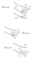
- Figure 4 illustrates three blades 100, 101 and 102 interconnected by a lacing wire 103.
- the lacing wire 103 is cut between the blades 100, 101, 102 so that only a stub like portion, as shown at 104, 105 and 106 in Figure 5 remains.
- the stubs are then removed by the machining apparatus which may be of the form as shown in Figures 1 and 3 and for example, referring to Figure 6, the blade 101 may be clamped by the supporting apparatus 26 and the machining apparatus is then moved in a direction substantially parallel to the rotor axis 27 until the machine bit 63 is moved in this first direction into contact with the lacing wire stub 105.
- the machining apparatus which may be of the form as shown in Figures 1 and 3 and for example, referring to Figure 6, the blade 101 may be clamped by the supporting apparatus 26 and the machining apparatus is then moved in a direction substantially parallel to the rotor axis 27 until the machine bit 63 is moved in this first direction into contact with the lacing wire stub 105.
- Movement of the machining apparatus then continues in the same direction until the machine bit 63 reaches the position as shown in Figure 7 in which a "flat" has been formed on the top of the lacing wire stub 105.
- the machining apparatus may then be moved in a downwards direction as shown in Figure 8 and the stub 105 removed by machining.
Landscapes
- Engineering & Computer Science (AREA)
- Mechanical Engineering (AREA)
- Turbine Rotor Nozzle Sealing (AREA)
- Hydraulic Turbines (AREA)
- Control Of Turbines (AREA)
- Application Of Or Painting With Fluid Materials (AREA)
Applications Claiming Priority (2)
| Application Number | Priority Date | Filing Date | Title |
|---|---|---|---|
| GB9000580 | 1990-01-10 | ||
| GB909000580A GB9000580D0 (en) | 1990-01-10 | 1990-01-10 | Apparatus for and methods of the repair of turbine blades |
Publications (3)
| Publication Number | Publication Date |
|---|---|
| EP0436933A2 true EP0436933A2 (de) | 1991-07-17 |
| EP0436933A3 EP0436933A3 (en) | 1991-09-04 |
| EP0436933B1 EP0436933B1 (de) | 1995-05-03 |
Family
ID=10669105
Family Applications (1)
| Application Number | Title | Priority Date | Filing Date |
|---|---|---|---|
| EP90125557A Expired - Lifetime EP0436933B1 (de) | 1990-01-10 | 1990-12-27 | Vorrichtung und Verfahren zum Wiederherstellen von Turbinenschaufeln |
Country Status (10)
| Country | Link |
|---|---|
| US (1) | US5081765A (de) |
| EP (1) | EP0436933B1 (de) |
| JP (1) | JPH054127A (de) |
| AT (1) | ATE121980T1 (de) |
| AU (1) | AU642456B2 (de) |
| CA (1) | CA2033827A1 (de) |
| DE (1) | DE69019134T2 (de) |
| GB (2) | GB9000580D0 (de) |
| IN (1) | IN179602B (de) |
| ZA (1) | ZA91139B (de) |
Cited By (13)
| Publication number | Priority date | Publication date | Assignee | Title |
|---|---|---|---|---|
| EP0890410A1 (de) * | 1996-04-30 | 1999-01-13 | United Technologies Corporation | Ein Rohling und eine Vorrichtung zum Herstellen von präzisen Formteilen |
| US6068541A (en) * | 1997-12-22 | 2000-05-30 | United Technologies Corporation | Method for using a fixture enabling more accurate machining of a part |
| US6139412A (en) * | 1996-04-30 | 2000-10-31 | United Technologies Corporation | Fixture for manufacturing precisely shaped parts |
| EP1946885A1 (de) * | 2006-12-12 | 2008-07-23 | General Electric Company | Vorrichtung zum Positionieren von Gasturbinenbauteilen |
| CN103831451A (zh) * | 2013-12-18 | 2014-06-04 | 浙江吉利控股集团有限公司 | 一种发动机暖风出水管专用加工工具及加工方法 |
| CN104669002A (zh) * | 2014-08-10 | 2015-06-03 | 安徽工程大学 | 一种加工机器人转座侧端面的专用提醒夹具 |
| CN106514352A (zh) * | 2016-12-28 | 2017-03-22 | 无锡透平叶片有限公司 | 用于方钢类叶片铣削加工的咬齿夹具 |
| CN106514360A (zh) * | 2016-12-30 | 2017-03-22 | 无锡透平叶片有限公司 | 用于榫齿叶片铣叶根的夹具装置 |
| CN107584180A (zh) * | 2017-09-28 | 2018-01-16 | 中国航发动力股份有限公司 | 一种串联式涡轮叶片多工位硬装夹电加工方法及装置 |
| CN109333412A (zh) * | 2018-12-07 | 2019-02-15 | 中国航发南方工业有限公司 | 涡轮转子组件的锁片分解工装 |
| CN109986146A (zh) * | 2017-12-29 | 2019-07-09 | 宁波方太厨具有限公司 | 一种用于侧吸油烟机下面板的攻丝工装 |
| CN111451560A (zh) * | 2020-04-30 | 2020-07-28 | 中国航发航空科技股份有限公司 | 一种航空发动机涡轮叶片叶冠减薄部的夹具及其加工方法 |
| CN112828725A (zh) * | 2020-12-22 | 2021-05-25 | 成都和鸿科技有限公司 | 超大燃机涡轮叶片加工工装及加工方法 |
Families Citing this family (18)
| Publication number | Priority date | Publication date | Assignee | Title |
|---|---|---|---|---|
| US5235745A (en) * | 1989-06-20 | 1993-08-17 | Refurbished Turbine Components Limited | Method of repairing turbine blades on a rotor |
| DE4237052A1 (de) * | 1992-11-03 | 1994-05-05 | Mtu Muenchen Gmbh | Vorrichtung zur Reparaturschweißung der Blattspitzen von Leit- oder Laufschaufeln für Turbomaschinen |
| GB2284367B (en) * | 1993-12-02 | 1997-02-26 | Turbine Blading Ltd | Turbine blade repair |
| US5758416A (en) * | 1996-12-05 | 1998-06-02 | General Electric Company | Method for repairing a turbine engine vane segment |
| JP4683442B2 (ja) * | 2000-07-13 | 2011-05-18 | 富士通フロンテック株式会社 | 処理装置および集積回路 |
| FR2817783B1 (fr) * | 2000-12-07 | 2003-02-21 | Snecma Moteurs | Outillage de maintien d'une aube, et son application au soudage par friction des aubes |
| US7204019B2 (en) * | 2001-08-23 | 2007-04-17 | United Technologies Corporation | Method for repairing an apertured gas turbine component |
| GB0308170D0 (en) * | 2003-04-09 | 2003-05-14 | Rolls Royce Plc | A mounting arrangement and method |
| GB0711697D0 (en) * | 2007-06-16 | 2007-07-25 | Rolls Royce Plc | Method of manufacture |
| US8151458B2 (en) * | 2008-02-21 | 2012-04-10 | United Technologies Corporation | Non-metallic cover for a fixture |
| US8713775B2 (en) * | 2011-06-16 | 2014-05-06 | General Electric Company | Apparatus and method for servicing dynamoelectric machine components in-situ |
| CN104722796B (zh) * | 2015-03-17 | 2018-06-19 | 青阳县鑫安特汽车零配件有限公司 | 一种汽车轴套钻孔装置 |
| GB201608639D0 (en) | 2016-05-17 | 2016-06-29 | Rolls Royce Plc | Fixture for holding a complex-shaped part during a machining operation |
| CN108723431A (zh) * | 2018-06-11 | 2018-11-02 | 芜湖拓达电子科技有限公司 | 一种便携式钢管穿孔装置 |
| CN109719537A (zh) * | 2019-02-28 | 2019-05-07 | 山东赫德能源科技有限公司 | 一种用于汽道加工的汽轮机叶片定位装夹系统 |
| CN110480381B (zh) * | 2019-09-05 | 2020-07-10 | 青岛艾斯达特汽车科技有限公司 | 一种锉削钻孔机械加工钳工作业工装夹具 |
| KR102127520B1 (ko) * | 2020-01-17 | 2020-06-26 | 주식회사 혜성하이테크 | 홀 성형 장치 |
| CN114749698A (zh) * | 2022-06-06 | 2022-07-15 | 浙江师范大学 | 一种专用于电焊钳的自动打孔装销钉装置及方法 |
Family Cites Families (10)
| Publication number | Priority date | Publication date | Assignee | Title |
|---|---|---|---|---|
| CH194231A (de) * | 1936-03-19 | 1937-11-30 | Hauser H Ag Ma | Lehrenbohrmaschine. |
| BE551845A (de) * | 1956-07-19 | |||
| US4033569A (en) * | 1976-10-15 | 1977-07-05 | Dunn Garf L | Deformation-preventing workpiece-holding fixture for machine tools |
| FR2416085A1 (fr) * | 1978-01-31 | 1979-08-31 | Hispano Suiza Sa | Systeme d'immobilisation d'aubes pendant leur usinage |
| US4276812A (en) * | 1978-03-27 | 1981-07-07 | Trw Inc. | Power steering valve and method of making the same |
| SU795708A1 (ru) * | 1979-02-22 | 1981-01-15 | Всесоюзный Проектно-Технологический Инсти-Тут Энергетического Машиностроения | Установка дл сборки и разборкиКлЕпАННыХ издЕлий |
| US4451959A (en) * | 1980-12-29 | 1984-06-05 | Elliott Turbomachinery Company, Inc. | Methods for securing a rotor blade within a rotor assembly and removing a rotor blade therefrom |
| DE3143846C2 (de) * | 1981-11-05 | 1983-11-03 | Messerschmitt-Bölkow-Blohm GmbH, 8000 München | Verwundenes Profil-Bauteil und Vorrichtung zur Bearbeitung von Polygonzug-Flächen |
| US4676719A (en) * | 1985-12-23 | 1987-06-30 | United Technologies Corporation | Film coolant passages for cast hollow airfoils |
| GB2227191B (en) * | 1988-09-16 | 1993-03-03 | Refurbished Turbine Components | Turbine blade repair |
-
1990
- 1990-01-10 GB GB909000580A patent/GB9000580D0/en active Pending
- 1990-12-20 GB GB9027624A patent/GB2240295B/en not_active Expired - Fee Related
- 1990-12-26 US US07/633,996 patent/US5081765A/en not_active Expired - Fee Related
- 1990-12-27 AT AT90125557T patent/ATE121980T1/de not_active IP Right Cessation
- 1990-12-27 DE DE69019134T patent/DE69019134T2/de not_active Expired - Fee Related
- 1990-12-27 EP EP90125557A patent/EP0436933B1/de not_active Expired - Lifetime
- 1990-12-31 IN IN1053MA1990 patent/IN179602B/en unknown
-
1991
- 1991-01-08 ZA ZA91139A patent/ZA91139B/xx unknown
- 1991-01-09 CA CA002033827A patent/CA2033827A1/en not_active Abandoned
- 1991-01-09 AU AU69221/91A patent/AU642456B2/en not_active Ceased
- 1991-01-10 JP JP3012364A patent/JPH054127A/ja active Pending
Cited By (19)
| Publication number | Priority date | Publication date | Assignee | Title |
|---|---|---|---|---|
| EP0890410A1 (de) * | 1996-04-30 | 1999-01-13 | United Technologies Corporation | Ein Rohling und eine Vorrichtung zum Herstellen von präzisen Formteilen |
| US5869194A (en) * | 1996-04-30 | 1999-02-09 | United Technologies Corporation | Blank for manufacturing precisely shaped parts |
| US6139412A (en) * | 1996-04-30 | 2000-10-31 | United Technologies Corporation | Fixture for manufacturing precisely shaped parts |
| US6068541A (en) * | 1997-12-22 | 2000-05-30 | United Technologies Corporation | Method for using a fixture enabling more accurate machining of a part |
| US6287182B1 (en) | 1997-12-22 | 2001-09-11 | United Technologies Corporation | Fixture for manufacturing precisely shaped parts |
| EP1946885A1 (de) * | 2006-12-12 | 2008-07-23 | General Electric Company | Vorrichtung zum Positionieren von Gasturbinenbauteilen |
| CN103831451B (zh) * | 2013-12-18 | 2016-05-18 | 浙江吉利罗佑发动机有限公司 | 一种发动机暖风出水管专用加工工具及加工方法 |
| CN103831451A (zh) * | 2013-12-18 | 2014-06-04 | 浙江吉利控股集团有限公司 | 一种发动机暖风出水管专用加工工具及加工方法 |
| CN104669002A (zh) * | 2014-08-10 | 2015-06-03 | 安徽工程大学 | 一种加工机器人转座侧端面的专用提醒夹具 |
| CN106514352A (zh) * | 2016-12-28 | 2017-03-22 | 无锡透平叶片有限公司 | 用于方钢类叶片铣削加工的咬齿夹具 |
| CN106514352B (zh) * | 2016-12-28 | 2019-01-04 | 无锡透平叶片有限公司 | 用于方钢类叶片铣削加工的咬齿夹具 |
| CN106514360A (zh) * | 2016-12-30 | 2017-03-22 | 无锡透平叶片有限公司 | 用于榫齿叶片铣叶根的夹具装置 |
| CN107584180A (zh) * | 2017-09-28 | 2018-01-16 | 中国航发动力股份有限公司 | 一种串联式涡轮叶片多工位硬装夹电加工方法及装置 |
| CN107584180B (zh) * | 2017-09-28 | 2019-09-17 | 中国航发动力股份有限公司 | 一种串联式涡轮叶片多工位硬装夹电加工方法及装置 |
| CN109986146A (zh) * | 2017-12-29 | 2019-07-09 | 宁波方太厨具有限公司 | 一种用于侧吸油烟机下面板的攻丝工装 |
| CN109333412A (zh) * | 2018-12-07 | 2019-02-15 | 中国航发南方工业有限公司 | 涡轮转子组件的锁片分解工装 |
| CN111451560A (zh) * | 2020-04-30 | 2020-07-28 | 中国航发航空科技股份有限公司 | 一种航空发动机涡轮叶片叶冠减薄部的夹具及其加工方法 |
| CN112828725A (zh) * | 2020-12-22 | 2021-05-25 | 成都和鸿科技有限公司 | 超大燃机涡轮叶片加工工装及加工方法 |
| CN112828725B (zh) * | 2020-12-22 | 2022-07-19 | 成都和鸿科技股份有限公司 | 超大燃机涡轮叶片加工工装及加工方法 |
Also Published As
| Publication number | Publication date |
|---|---|
| CA2033827A1 (en) | 1991-07-11 |
| AU6922191A (en) | 1991-07-11 |
| US5081765A (en) | 1992-01-21 |
| GB2240295A (en) | 1991-07-31 |
| EP0436933A3 (en) | 1991-09-04 |
| ZA91139B (en) | 1992-04-29 |
| JPH054127A (ja) | 1993-01-14 |
| AU642456B2 (en) | 1993-10-21 |
| DE69019134D1 (de) | 1995-06-08 |
| IN179602B (de) | 1997-11-01 |
| GB9027624D0 (en) | 1991-02-13 |
| GB9000580D0 (en) | 1990-03-14 |
| GB2240295B (en) | 1993-06-23 |
| ATE121980T1 (de) | 1995-05-15 |
| DE69019134T2 (de) | 1995-09-14 |
| EP0436933B1 (de) | 1995-05-03 |
Similar Documents
| Publication | Publication Date | Title |
|---|---|---|
| EP0436933B1 (de) | Vorrichtung und Verfahren zum Wiederherstellen von Turbinenschaufeln | |
| US5168608A (en) | Apparatus for the repair of turbine blades | |
| CN101092012B (zh) | 部件夹持装置 | |
| EP0359585B1 (de) | Reparatur einer Turbinenschaufel | |
| EP0524599B1 (de) | Verfahren zur Herstellung von Rahmen für rohrförmige Teile und Rahmen hergestellt mit diesem Verfahren | |
| JPS6317626Y2 (de) | ||
| US5871314A (en) | Device for balancing rotors by material removal | |
| EP0404020B1 (de) | Reparatur einer Turbinenschaufel | |
| EP0462487B1 (de) | Reparaturweise von Turbinenschaufeln | |
| CN108115209B (zh) | 涡轮叶片的切削加工的方法 | |
| US5235745A (en) | Method of repairing turbine blades on a rotor | |
| JP2005536361A (ja) | クランプ組立品 | |
| US6298757B1 (en) | System for presetting the cutting tools of a cut-off machine for a pipe or a shaft | |
| US6540455B1 (en) | Machine and method for circumferentially milling a cylindrical work piece | |
| US3396613A (en) | Jig for use with a machine tool | |
| US3592103A (en) | Apparatus for removing material from a workpiece | |
| EP2826590B1 (de) | Werkzeug zur dynamischen befestigung von zu bearbeitenden teilen | |
| AU682717B2 (en) | Apparatus for machining turbine blades | |
| US5171110A (en) | Apparatus and method for counterboring a pipe | |
| US4348839A (en) | Method for producing surfaces at a blade cutter head formed of hardened cutter blade steel | |
| RU2733751C1 (ru) | Устройство для снятия наружной изоляции с концов и/или подготовки торцов труб | |
| JP3597705B2 (ja) | 穴の機械加工方法 | |
| KR20180051247A (ko) | 공작기계장치 | |
| SU1491629A1 (ru) | Станок дл заточки боковых сторон зубьев пил | |
| CN107378563A (zh) | 一种数控旋转角度夹具 |
Legal Events
| Date | Code | Title | Description |
|---|---|---|---|
| PUAI | Public reference made under article 153(3) epc to a published international application that has entered the european phase |
Free format text: ORIGINAL CODE: 0009012 |
|
| PUAL | Search report despatched |
Free format text: ORIGINAL CODE: 0009013 |
|
| AK | Designated contracting states |
Kind code of ref document: A2 Designated state(s): AT BE CH DE DK ES FR GR IT LI LU NL SE |
|
| AK | Designated contracting states |
Kind code of ref document: A3 Designated state(s): AT BE CH DE DK ES FR GR IT LI LU NL SE |
|
| 17P | Request for examination filed |
Effective date: 19920302 |
|
| 17Q | First examination report despatched |
Effective date: 19930205 |
|
| GRAA | (expected) grant |
Free format text: ORIGINAL CODE: 0009210 |
|
| AK | Designated contracting states |
Kind code of ref document: B1 Designated state(s): AT BE CH DE DK ES FR GR IT LI LU NL SE |
|
| PG25 | Lapsed in a contracting state [announced via postgrant information from national office to epo] |
Ref country code: GR Free format text: LAPSE BECAUSE OF FAILURE TO SUBMIT A TRANSLATION OF THE DESCRIPTION OR TO PAY THE FEE WITHIN THE PRESCRIBED TIME-LIMIT Effective date: 19950503 Ref country code: ES Free format text: THE PATENT HAS BEEN ANNULLED BY A DECISION OF A NATIONAL AUTHORITY Effective date: 19950503 Ref country code: DK Effective date: 19950503 |
|
| REF | Corresponds to: |
Ref document number: 121980 Country of ref document: AT Date of ref document: 19950515 Kind code of ref document: T |
|
| REF | Corresponds to: |
Ref document number: 69019134 Country of ref document: DE Date of ref document: 19950608 |
|
| ITF | It: translation for a ep patent filed | ||
| PG25 | Lapsed in a contracting state [announced via postgrant information from national office to epo] |
Ref country code: SE Effective date: 19950803 |
|
| ET | Fr: translation filed | ||
| PLBE | No opposition filed within time limit |
Free format text: ORIGINAL CODE: 0009261 |
|
| STAA | Information on the status of an ep patent application or granted ep patent |
Free format text: STATUS: NO OPPOSITION FILED WITHIN TIME LIMIT |
|
| 26N | No opposition filed | ||
| PGFP | Annual fee paid to national office [announced via postgrant information from national office to epo] |
Ref country code: DE Payment date: 19990115 Year of fee payment: 9 |
|
| PGFP | Annual fee paid to national office [announced via postgrant information from national office to epo] |
Ref country code: FR Payment date: 19990126 Year of fee payment: 9 |
|
| PGFP | Annual fee paid to national office [announced via postgrant information from national office to epo] |
Ref country code: LU Payment date: 19990127 Year of fee payment: 9 Ref country code: AT Payment date: 19990127 Year of fee payment: 9 |
|
| PGFP | Annual fee paid to national office [announced via postgrant information from national office to epo] |
Ref country code: NL Payment date: 19990131 Year of fee payment: 9 |
|
| PGFP | Annual fee paid to national office [announced via postgrant information from national office to epo] |
Ref country code: CH Payment date: 19990210 Year of fee payment: 9 |
|
| PGFP | Annual fee paid to national office [announced via postgrant information from national office to epo] |
Ref country code: BE Payment date: 19990215 Year of fee payment: 9 |
|
| PG25 | Lapsed in a contracting state [announced via postgrant information from national office to epo] |
Ref country code: LU Free format text: LAPSE BECAUSE OF NON-PAYMENT OF DUE FEES Effective date: 19991227 Ref country code: AT Free format text: LAPSE BECAUSE OF NON-PAYMENT OF DUE FEES Effective date: 19991227 |
|
| PG25 | Lapsed in a contracting state [announced via postgrant information from national office to epo] |
Ref country code: LI Free format text: LAPSE BECAUSE OF NON-PAYMENT OF DUE FEES Effective date: 19991231 Ref country code: CH Free format text: LAPSE BECAUSE OF NON-PAYMENT OF DUE FEES Effective date: 19991231 Ref country code: BE Free format text: LAPSE BECAUSE OF NON-PAYMENT OF DUE FEES Effective date: 19991231 |
|
| BERE | Be: lapsed |
Owner name: REFURBISHED TURBINE COMPONENTS LTD Effective date: 19991231 |
|
| PG25 | Lapsed in a contracting state [announced via postgrant information from national office to epo] |
Ref country code: NL Free format text: LAPSE BECAUSE OF NON-PAYMENT OF DUE FEES Effective date: 20000701 |
|
| PG25 | Lapsed in a contracting state [announced via postgrant information from national office to epo] |
Ref country code: FR Free format text: LAPSE BECAUSE OF NON-PAYMENT OF DUE FEES Effective date: 20000831 |
|
| NLV4 | Nl: lapsed or anulled due to non-payment of the annual fee |
Effective date: 20000701 |
|
| PG25 | Lapsed in a contracting state [announced via postgrant information from national office to epo] |
Ref country code: DE Free format text: LAPSE BECAUSE OF NON-PAYMENT OF DUE FEES Effective date: 20001003 |
|
| REG | Reference to a national code |
Ref country code: FR Ref legal event code: ST |
|
| PG25 | Lapsed in a contracting state [announced via postgrant information from national office to epo] |
Ref country code: IT Free format text: LAPSE BECAUSE OF NON-PAYMENT OF DUE FEES Effective date: 20051227 |