EP0436956A2 - Drehzahlsteuergerät für Brennkraftmaschine mit Hilfsluftregler - Google Patents
Drehzahlsteuergerät für Brennkraftmaschine mit Hilfsluftregler Download PDFInfo
- Publication number
- EP0436956A2 EP0436956A2 EP90125762A EP90125762A EP0436956A2 EP 0436956 A2 EP0436956 A2 EP 0436956A2 EP 90125762 A EP90125762 A EP 90125762A EP 90125762 A EP90125762 A EP 90125762A EP 0436956 A2 EP0436956 A2 EP 0436956A2
- Authority
- EP
- European Patent Office
- Prior art keywords
- control
- engine
- control amount
- state
- accordance
- Prior art date
- Legal status (The legal status is an assumption and is not a legal conclusion. Google has not performed a legal analysis and makes no representation as to the accuracy of the status listed.)
- Granted
Links
Images


Classifications
-
- F—MECHANICAL ENGINEERING; LIGHTING; HEATING; WEAPONS; BLASTING
- F02—COMBUSTION ENGINES; HOT-GAS OR COMBUSTION-PRODUCT ENGINE PLANTS
- F02D—CONTROLLING COMBUSTION ENGINES
- F02D41/00—Electrical control of supply of combustible mixture or its constituents
- F02D41/02—Circuit arrangements for generating control signals
- F02D41/18—Circuit arrangements for generating control signals by measuring intake air flow
-
- F—MECHANICAL ENGINEERING; LIGHTING; HEATING; WEAPONS; BLASTING
- F02—COMBUSTION ENGINES; HOT-GAS OR COMBUSTION-PRODUCT ENGINE PLANTS
- F02D—CONTROLLING COMBUSTION ENGINES
- F02D31/00—Use of speed-sensing governors to control combustion engines, not otherwise provided for
- F02D31/001—Electric control of rotation speed
- F02D31/002—Electric control of rotation speed controlling air supply
- F02D31/003—Electric control of rotation speed controlling air supply for idle speed control
- F02D31/005—Electric control of rotation speed controlling air supply for idle speed control by controlling a throttle by-pass
Definitions
- the present invention relates to an engine speed control apparatus having an auxiliary air amount controller for controlling an amount of auxiliary air which is supplied to the engine from an auxiliary air passage provided so as to bypass a throttle valve which is arranged in an intake pipe of the engine and, more particularly, to the control of an auxiliary air amount upon shifting from a non-idling state of the engine to an idling state.
- an auxiliary air amount controller for an engine for setting a control gain in accordance with a reduction ratio of a rotational speed in order to prevent a decrease in rotational speed upon shifting from the non-idling state of the engine to the idling state and to improve a converging performance to a target engine speed (for instance, JP-A-62-253941 and the like).
- the controller to control the auxiliary air amount in accordance with the reduction ratio of the rotational speed as mentioned above merely executes a forward control. That is, an air amount (necessary air amount) which is needed by the engine in order to prevent a decrease in rotational speed upon shifting from the non-idling state of the engine to the idling state and to improve the converging performance to the target engine speed differs depending on a difference of the engine, an engine state, and the like. Therefore, there is a problem such that it is difficult to accurately control the auxiliary air amount so as to obtain the necessary air amount.
- the invention is made in consideration of the above problems and it is an object of the invention to provide an engine speed control apparatus with an auxiliary air amount controller for an engine which can accurately control an air amount which is supplied to the engine to a necessary air amount upon shifting from the non-idling state of the engine to the idling state.
- the first invention provides an engine speed control apparatus with an engine auxiliary air amount controller having an actuator which is arranged in an auxiliary air passage for leading an auxiliary air from the upstream side of a throttle valve arranged in an intake manifold of the engine to the downstream side of the throttle valve by bypassing the throttle valve and adjusts a flow rate of the auxiliary air and actuator control means for controlling the actuator so that intake information in the downstream of the throttle valve coincides with a target value
- the actuator control means comprises: rotational speed detecting means for detecting an engine speed; control start timing detecting means for detecting a timing to start a control by the actuator control means in accordance with the engine state; and target value setting means for setting the target value of the intake information in accordance with the rotational speed at the control start timing which is detected.
- the second invention provides an engine speed control apparatus with an engine auxiliary air amount controller having an actuator which is arranged in an auxiliary air passage for leading an auxiliary air from the upstream side of a throttle valve which is arranged in an intake manifold of the engine to the downstream side of the throttle valve by bypassing the throttle valve and adjusts a flow rate of the auxiliary air and actuator control means for controlling the actuator so that intake information in the downstream of the throttle valve coincides with a target value
- the actuator control means comprises: intake information detecting means for detecting means for detecting the intake information; and control amount setting means for setting a control amount of the actuator in accordance with a time differentiation value of the target intake information and a time differentiation value of the intake information.
- the target value of the intake information is set by the target value setting means in accordance with the rotational speed at the timing to start the control by the actuator control means which is detected by the control start timing detecting means in accordance with the engine state.
- the actuator is controlled so that the intake information coincides with the target intake information.
- a control amount of the actuator is set by the control amount setting means in accordance with the time differentiation value of the target value of the intake information and the time differentiation value of the intake information.
- the target intake pressure is set in accordance with the time differentiation value of the rotational speed in a discriminating step.
- the auxiliary air amount is controlled so that the intake pressure coincides with the target intake pressure. Therefore, upon shifting from the non-idling state to the idling state, the air amount can be accurately controlled to an air amount which is required by the engine. Thus, there are excellent effects such that a decrease in rotational speed can be prevented and the converging performance to the target rotational speed can be improved.
- the auxiliary air amount is set in accordance with the time differentiation value of the target intake pressure and the time differentiation value of the intake pressure, so that the intake pressure can be accurately controlled to the target intake pressure. Consequently, there is an excellent effect such that the air amount can be accurately controlled to an air amount which is required by the engine.
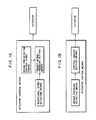
- Fig. 2 is a constructional diagram of an embodiment.
- a throttle valve 12 is arranged on the upstream side of a surge tank 11 and an idling switch 13 which is turned on when the throttle valve 12 is in a full-closed state is attached.
- An auxiliary air passage 14 is provided so as to supply the air from the upstream side of the throttle valve to the surge tank 11 on the downstream side of the throttle valve by bypassing the throttle valve 12.
- An idling control valve (ISC valve) 15 for controlling an auxiliary air amount is arranged in the auxiliary air passage 14.
- a well-known proportional electromagnetic type (linear solenoid) control valve or vacuum switching valve (VSV) or the like is properly used as the ISC valve 15.
- a temperature sensor 16 for detecting an intake air temperature is attached on the upstream side of the throttle valve 12. Further, a pressure sensor 17 for detecting an intake pressure P in the downstream of the throttle valve 12 is attached to the surge tank 11. Further, the surge tank 11 is communicated with a combustion chamber of the engine 10 via an intake manifold 18 and an intake port 19. A fuel injection valve 20 is attached every cylinder so as to be projected into the intake manifold 18.
- the combustion chamber of the engine 10 is connected to a 3-way catalytic converter (not shown) via an exhaust port 21 and an exhaust manifold 22.
- An O2 sensor 23 for detecting a residual oxygen concentration in the exhaust gas and outputting an air-fuel ratio signal is attached to the exhaust manifold 22.
- a water temperature sensor 25 is attached to an engine block 24 so as to penetrate the engine block 24 and project into a water jacket in order to detect a temperature of a cooling water for the engine 10.
- a spark plug 27 is attached every cylinder so as to penetrate through cylinder head 26 of the engine 10 and project into the combustion chamber.
- the spark plug 27 is connected to an electronic control unit (ECU) 50 comprising a microcomputer or the like through a distributor 28 and an igniter 29.
- ECU electronice control unit
- a cylinder discriminating sensor 30 and a crank angle sensor 31 each of which is constructed by a signal rotor fixed to a distributor shaft and a pickup fixed to a distributor housing are attached in the distributor 28.
- the cylinder discrimination sensor 30 outputs a cylinder discrimination signal, for instance, every 720°CA and the crank angle sensor 31 outputs a rotational speed signal, for example, every 30°CA.
- the ECU 50 is constructed so as to include: a central processing unit (CPU) 51; a read only memory (ROM) 52; a random access memory (RAM) 53; a backup RAM (BU-RAM) 54; an input/output port 55; an analog/digital converter (ADC) 56; and a bus 57 such as data bus, control bus, and the like for connecting the above components.
- the cylinder discrimination signal, rotational speed signal, throttle full-close signal, and air-fuel ratio signal are input to the input/output port (I/O port) 55.
- the I/O port 55 outputs an ISC valve control signal to open or close the ISC valve 15, a fuel injection signal to open or close the fuel injection valve 20, and an ignition signal to turn on or off the igniter 29 to a driving circuit (not shown).
- the driving circuit controls the ISC valve 15, fuel injection valve 20, and igniter 29, respectively.
- an intake pressure signal, an intake air temperature signal, and a water temperature signal are input to the ADC 56.
- the ADC 56 sequentially converts the above signals into the digital signals in accordance with commands from the CPU 51.
- the auxiliary air amount G ISC is determined in accordance with a difference between the time differentiation value dP t /dt of the target intake pressure P t and the time differentiation value dP/dt of the intake pressure P.
- V S /RT can be considered to be a constant.
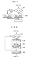
- Fig. 4 shows a timing chart of the rotational speed in the deceleration fuel cutting mode.
- a solid line 1 in (a) in Fig. 4 shows the ideal behavior of the rotational speed. That is, the rotational speed decreases to the target rotational speed and, thereafter, it is maintained to the target rotational speed.
- the target intake pressure P t is set to the intake pressure in the case where the rotational speed exhibited the ideal behavior (ideal rotational speed) as mentioned above.
- the ideal rotational speed linearly decreases until the target rotational speed here. That is, the ideal rotational speed can be set in accordance with the time differentiation value of the rotational speed just before the engine is returned from the fuel cutting mode.
- Fig. 5 shows the relation (contour line for an equal quantity delivery of air) between the rotational speed N and the intake pressure P for supplying an air amount which is necessary to maintain a stationary state in the idling mode.
- the target intake pressure P t can be set on the basis of the contour line for an equal quantity delivery of air from the ideal rotational speed which is presumed in accordance with the time differentiation value of the rotational speed just before the engine is returned from the fuel cutting mode.
- step 90 a state of the idling switch 13 is detected in step 90. Only when the idling switch 13 is on, the control of the auxiliary air amount in step 100 and subsequent steps is executed.
- step 100 the intake pressure P which is detected by the pressure sensor 17 and the rotational speed N which is calculated on the basis of the detection signal of the crank angle sensor 31 are read.
- step 101 a check is made to see if the fuel is in the cutting state or not. If the fuel is in the cutting state, it is determined that the operating mode is in the non-idling state, so that step 102 follows.
- step 102 the rotational speed N is set to an ideal rotational speed N e as a parameter to set the initial value of the target intake pressure P t in the feedback control of the auxiliary air amount. Then, step 103 follows.
- step 104 the processing routine advances to step 104 and a check is made to see if the intake pressure P is equal to a predetermined pressure (for instance, intake pressure in the idling stable state or the like) P IDL or not. If the intake pressure P is equal to or higher than the predetermined value P IDL , step 103 follows without executing the feedback control of the auxiliary air amount.
- the auxiliary air amount G ISC is set to a predetermined amount (for example, learning value of the auxiliary air amount in the idling state) G LRN . That is, the auxiliary air amount G ISC in the case where the feedback control is not executed is set to the predetermined amount G LRN .
- step 104 if it is determined in step 104 that the intake pressure P is small than the predetermined pressure P IDL , the feedback control in step 105 and subsequent steps is performed.
- step 105 a state of a flag FCUT is detected.
- the flag FCUT is reset (FCUT ⁇ 0) when the fuel is cut.
- the flag FCUT is set (FCUT ⁇ 1) when the feedback control is started. If the flag FCUT is not set, it is determined that the engine was returned from the fuel cutting state at the present control timing, that is, the operating mode was shifted from the non-idling state to the idling state, thereby starting the feedback control.
- step 106 a deviation between the rotational speed N at the present control timing and a rotational speed N0 at the preceding control timing is set as a time differentiation value ⁇ N ( ⁇ N - N0) of the rotational speed.
- step 107 the flag FCUT is set (FCUT ⁇ 1) and step 108 follows.
- step 105 If it is decided in step 105 that the flag FCUT has been set, namely, when the engine has already been set into the idling state, the processes in steps 106 and 107 are not executed but step 108 follows.
- step 108 the target rotational speed N e is set by the following equation. N e ⁇ N e + ⁇ N
- the target intake pressure P t is set in accordance with the ideal rotational speed N e from the contour line for an equal quantity delivery of air shown in Fig. 5 as mentioned above.
- a deviation between the intake pressure P at the present control timing and the intake pressure P0 at the preceding control timing is set as a time differentiation value ⁇ P ( ⁇ P - P0) of the intake pressure.
- a deviation between the target intake pressure P t which was set at the present control timing and a target intake pressure P to which was set at the preceding control timing is set as a time differentiation value ⁇ P t ( ⁇ P t - P t0 ) of the target intake pressure.
- the auxiliary air amount G ISC is set by the following equation in accordance with the time differentiation value ⁇ P t of the target intake pressure and the time differentiation value ⁇ P of the intake pressure on the basis of the equation (1).
- a control signal (duty signal) corresponding to the auxiliary air amount G ISC which was set as mentioned above is output to the ISC valve 15.
- a state in which the idling switch 13 is on and the fuel is not in the cutting state is called an idling state.
- the auxiliary air amount G ISC is supplied so that the intake pressure P is equal to the target intake pressure P t .
- the target intake pressure P t is set in accordance with the ideal rotational speed N e which is set on the basis of the time differentiation value ⁇ N of the rotational speed when the engine is returned from the fuel cutting state, that is, when shifting from the non-idling state to the idling state. Therefore, the auxiliary air amount G ISC can be controlled so that the intake pressure P provides the ideal rotational speed N e .
- the auxiliary air amount G ISC is set in accordance with the time differentiation value dP t /dt of the target intake pressure P t and the time differentiation value dP/dt of the intake pressure P. Therefore, the intake pressure P can be accurately controlled to the target intake pressure P t .
- the auxiliary air amount G ISC is set in accordance with the time differentiation value ⁇ P t of the target intake pressure and the time differentiation value ⁇ P of the intake pressure.
- the auxiliary air amount G ISC can be also set in accordance with the difference between the target intake pressure P t and the intake pressure P.
- step 201 the magnitude of the target intake pressure P t which was set in step 109 is compared with the magnitude of the intake pressure P. If the intake pressure P is larger than the target intake pressure P t , the auxiliary air amount G ISC is set in step 202 by the following equation. G ISC ⁇ G ISC + K1 ⁇ (P t - P) where, K1 is a first proportional constant.
- the auxiliary air amount G ISC is set in step 203 by the following equation.
- the integration constant is set to a larger value, thereby controlling so as to rapidly reach the target intake pressure P t .
- the target intake pressure P t has been set every predetermined control timing on the basis of the ideal rotational speed N e , thereby obtaining the time differentiation value ⁇ P t of the target intake pressure from the deviation between the intake pressure P and the target intake pressure P t .
- the time differentiation value ⁇ P t of the target intake pressure can be also set by the time differentiation value ⁇ N of the rotational speed when the engine is returned from the fuel cutting state.
- the processes in steps 105 to 302 are executed in place of the processes in steps 105 to 111 in the flowchart of Fig. 6 and the other process are the same as those in Fig. 6. Therefore, the description of the other processes is omitted here.
- step 105 the time differentiation value ⁇ N of the rotational speed is set in step 106 as mentioned above.
- step 301 the target intake pressure ⁇ P t is set in accordance with the time differentiation value ⁇ N of the rotational speed.
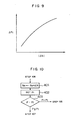
- Fig. 9 shows a characteristic diagram between the time differentiation value ⁇ N of the rotational speed and the target intake pressure ⁇ P t .
- step 107 the flag FCUT is then set (FCUT ⁇ 1).
- step 302 the time differentiation value of the intake pressure is set. The process in step 112 in Fig. 6 is executed.
- the auxiliary air amount G ISC has been controlled only in the case of cutting the fuel upon deceleration.
- the auxiliary air amount can be also controlled upon shifting from the non-idling state in which the fuel is not cut to the idling state as in the case of the deceleration at a low speed.
- the fourth embodiment will now be described hereinbelow on the basis of a flowchart shown in Fig. 10.
- the processes in steps 401 to 403 are executed between steps 106 and 107 in the flowchart shown in Fig. 6 and the process in step 90 is omitted.
- the other processes are the same as those in the flowchart of Fig. 6. Therefore, only the processes in steps 401 to 403 in Fig. 10 will be described.
- step 401 the ideal rotational speed N e is set.
- step 402 the target intake pressure P t is set in accordance with the ideal rotational speed N e as mentioned above.
- step 403 the magnitude of the intake pressure P is compared with the magnitude of the target intake pressure P t .
- the intake pressure P is larger than the target intake pressure P t , it is decided that the operating mode is in the non-idling state, so that the processing routine advances to step 103 without executing the feedback control.
- step 107 follows to execute the feedback control.
- the flag FCUT in the fourth embodiment is set in the idling state and is reset in the non-idling state.
- the control routine is started and executed every predetermined time (for instance, 100 msec in the embodiment).
- a state of the idling switch 13 is detected in step 500. If the idling switch 13 is off, the control amount calculating routine in step 504 and subsequent steps is not executed but the processing routine advances to step 502. In step 502, a flag MODE1 indicative of the control state of the ISC valve 15 is set to 0 (MODE1 ⁇ 0) and the control routine is finished. That is, if the flag MODE1 has been set to 0, this means a state in which the calculation of the control amount G ISC is not performed.
- step 504 the control amount calculating routine in step 504 and subsequent steps is executed.
- step 504 the intake pressure P which is detected by the pressure sensor 17 and the rotational speed N which is calculated on the basis of the detection signal of the crank angle sensor 31 are read.
- step 506 the state of the flag MODE1 is detected. If the flag MODE1 has been set to 0, that is, if the idling switch 13 was changed from the off state to the on state at the present control timing, in other words, in the case of starting the calculation of the control amount G ISC form the present control timing, the processing routine advances to step 508.
- Steps 508 to 516 relate to the initializing routine.
- a predetermined control amount G LRN is set in accordance with a load state of the engine 10 and step 510 follows.
- a learning control amount corresponding to the load state at that time among learning control amounts G LRN1 , G LRN2 , and G LRN3 stored in the BU-RAM 54 is set as a predetermined control amount G LRN in accordance with the load state (an operating state of an air conditioner, an electrical load state, etc.) of the engine 10 as will be explained hereinlater.
- the predetermined control amount G LRN which was set in step 508 is set as a control amount G ISC in step 510.
- the target intake pressure P t is set in step 512, in a manner similar to the foregoing embodiments (step 109 in Fig. 6, step 301 in Fig. 8, step 402 in Fig. 10).
- an intake pressure deviation DP is reset (DP ⁇ 0).
- the intake pressure deviation DP is a deviation between the time differentiation value ⁇ P t of the target intake pressure and the time differentiation value ⁇ P r of the intake pressure as will be explained hereinlater.
- the control amount G ISC is set in accordance with the intake pressure deviation DP.
- the flag MODE1 is set to "1" (MODE1 ⁇ 1) and the control routine is finished. That is, when the flag MODE1 is set to 1, this means a state in which the calculation of the control amount G ISC has been executed.
- step 518 follows and a check is made to see if the flag MODE1 has been set to 1 or not. If the flag MODE1 has been set to 1, namely,in the case of executing the calculation of the control amount G ISC , step 520 follows.
- step 520 the time differentiation value ⁇ P r of the intake pressure is calculated ( ⁇ P r ⁇ P0 - P: where, P0 denotes an intake pressure at the preceding control timing).
- step 522 the target intake pressure P t is set in a manner similar to step 512.
- step 524 the time differentiation value ⁇ P t of the target intake pressure is calculated ( ⁇ P t ⁇ P t 0 - P t : where, P t 0 denotes a target intake pressure at the preceding control timing).
- step 526 a check is made to see if the time differentiation value ⁇ P r of the intake pressure is equal to or larger than 0 or not. If the time differentiation value ⁇ P r of the intake pressure is equal to or larger than 0, step 528 follows. A deviation between the time differentiation value ⁇ P t of the target intake pressure and the time differentiation value ⁇ P r of the intake pressure is substituted for the intake pressure deviation DP (DP ⁇ ⁇ P t - ⁇ P r ) and step 532 follows. On the other hand, if the time differentiation value ⁇ P r of the intake pressure is less than 0 in step 526, step 530 follows. In step 530, the intake pressure deviation DP is reset (DP ⁇ 0) and step 532 follows.
- the control amount G ISC is set in accordance with the intake pressure deviation DP in step 532.
- the intake pressure deviation DP is increased by a predetermined number (K) of times, the resultant value is added to a control amount G ISC 0 at the preceding control timing, and the resultant value is set to the control amount G ISC (G ISC ⁇ G ISC 0 + K ⁇ DP).
- the intake pressure deviation DP is increased by a predetermined number (K) of times, the resultant value is added to the control amount G ISC 0 which was set at the preceding control timing, and the resultant value is set as a control amount G ISC .
- Steps 534 to 540 relate to a guarding process of the control amount G ISC in the case during the arming up or running.
- step 534 a check is made to see if the engine is in the warming up or running state or not. If the engine is not in the warming up or running state, step 542 follows.
- step 536 follows.
- the predetermined control amount G LRN is set in accordance with the load state in a manner similar to step 508.
- step 538 a check is made to see if the control amount G ISC which was set in step 532 is less than the predetermined control amount G LRN or not. If the control amount G ISC is equal to or larger than the predetermined control amount G LRN , step 542 follows. If the control amount G ISC is less than the predetermined control amount G LRN in step 538, step 540 follows. In step 540, the control amount G ISC is reset to the predetermined control amount G LRN and step 542 follows.
- Step 542 relates to an end discriminating process.
- the end discriminating process will now be described on the basis of a flowchart shown in Fig. 12.
- a predetermined intake pressure P ISC is set in accordance with the load state of the engine 10.
- the learning intake pressure corresponding to the load state at that time among the learning intake pressures P LRN1 , P LRN2 , and P LRN3 stored in the BU-RAM 54 is set as a predetermined intake pressure P ISC in accordance with the load state.
- step 602 if the intake pressure P is equal to or larger than the predetermined intake pressure P ISC , step 628 follows.
- step 604 if the intake pressure P is less than the predetermined intake pressure P ISC , step 604 follows.
- step 604 a check is made to see if the time differentiation value ⁇ N of the rotational speed is equal to or less than a first predetermined value N1 or not. If the time differentiation value ⁇ N of the rotational speed is larger than the first predetermined value N1, step 606 follows. In step 606, a counter CN is reset (CN ⁇ 0) and step 612 follows. The counter CN is used to detect a continuation time of a state in which the time differentiation value ⁇ N of the rotational speed is equal to or less than the first predetermined value N1.
- step 604 if the time differentiation value ⁇ N of the rotational speed is equal to or less than the first predetermined value N1, step 608 follows and the counter CN is counted up
- step 610 a check is made to see if the count value of the counter CN is equal to or larger than a first count value KCN or not, that is, whether a continuation time of a sate in which the time differentiation value ⁇ N of the rotational speed is equal to or less than the first predetermined value N1 is equal to or longer than a first predetermined time or not. If the count value of the counter CN is equal to or larger than the first count value KCN, step 628 follows. On the contrary, if the count value of the counter CN is less than the first count value KCN in step 610, step 612 follows.
- step 612 a check is made to see if the time differentiation value ⁇ P r of the intake pressure is equal to or less than a second predetermined value P1 or not. If the time differentiation value ⁇ P r of the intake pressure is larger than the second predetermined value P1, step 614 follows.
- a counter CP is reset (CP ⁇ 0) and step 620 follows. The counter CP detects a continuation time of a state in which the time differentiation value ⁇ P r of the intake pressure is equal to or less than the second predetermined value P1.
- step 612 if the time differentiation value ⁇ P r of the intake pressure is equal to or less than the second predetermined value P1, step 616 follows and the counter CP is counted up
- step 618 a check is made to see if the value of the counter CP is equal to or larger than a second count value KCP or not, that is, whether a continuation time of a state in which the time differentiation value ⁇ P r of the intake pressure is equal to or less than a second predetermined value P1 is equal to or longer than a second predetermined time or not. If the count value of the counter CP is equal to or larger than the second count value KCP, step 628 follows. On the contrary, if the value of the counter CP is less than the second count value KCP in step 618, step 620 follows.
- step 620 the predetermined control amount G LRN is set in accordance with the load state of the engine 10 in a manner similar to step 508 in Fig. 11 mentioned above.
- step 622 a check is made to see if the control amount G ISC is equal to or less than the predetermined control amount G LRN or not. If the control amount G ISC is larger than the predetermined control amount G LRN , step 624 follows. In step 624, a counter CG is reset (CG ⁇ 0) and the processing routine is finished. The counter CG detects a continuation time of a state in which the control amount G ISC is equal to or less than the predetermined control amount G LRN .
- step 622 if the control amount G ISC is equal to or less than the predetermined control amount G LRN , step 626 follows and the counter CG is counted up (CG ⁇ CG + 1).
- step 628 a check is made to see if the count value of the counter CG is equal to or larger than a third count value KCG or not, namely, whether a continuation time of a state in which the control amount G ISC is equal to or less than the predetermined control amount G LRN is equal to or longer than a third predetermined time or not. If the value of the counter CG is equal to or larger than the third count value KCG, step 630 follows. On the other hand, in step 628, if the value of the counter CG is less than the third count value KCG, the processing routine is finished.
- Steps 630 to 634 relate to a finishing routine which is executed when it is determined that the deceleration control is finished.
- the predetermined control amount G LRN is set in accordance with the load state of the engine 10 in a manner similar to step 620 mentioned above and step 632 follows.
- the control amount G ISC is reset to the predetermined control amount G LRN (G ISC ⁇ G LRN ) and step 634 follows.
- the flag MODE1 is set to 2 (MODE1 ⁇ 2). If the flag MODE1 has been set to 2, this means that the idling control (ISC control) is executed.
- the description of the end discriminating process in step 542 in Fig. 11 is finished.
- step 518 if the flag MODE1 is not 1, that is, if the flag MODE1 has been set to 2, step 544 follows and the ISC control is executed.
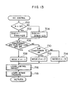
- the ISC control in step 544 will now be described hereinbelow on the basis of a flowchart shown in Fig. 13.
- Steps 700 to 704 relate to a processing routine to set the control amount G ISC in a manner such that the rotational speed N coincides with a target rotational speed NT which is set in accordance with the engine state such as a water temperature or the like.
- step 700 a check is made to see if the rotational speed N is less than the target rotational speed NT or not. If the rotational speed N is less than the target rotational speed NT, step 702 follows. In step 702, only a predetermined amount ⁇ G is added to the control amount G ISC 0 which was set at the preceding control timing and the resultant value is set as the control amount G ISC and step 706 follows.
- step 700 a check is made to see if the rotational speed N is less than the target rotational speed NT or not. If the rotational speed N is equal to or larger than the target rotational speed NT, step 704 follows. In step 704, only a predetermined amount ⁇ G is subtracted from the control amount G ISC 0 which was set at the preceding control timing and the resultant value is set as the control amount G ISC and step 706 follows.
- Steps 706 to 714 relate to a processing routine to detect the load state of the engine 10.
- steps 706 states of the air conditioner and the electric load are detected. If both of the air conditioner and the electric load are off, step 708 follows.
- a flag MODE2 is set to 1 (MODE2 ⁇ 1) and step 716 follows.
- the flag MODE2 shows the load state of the engine 10.
- step 706 the state of the air conditioner is detected. If the air conditioner is on, step 712 follows.
- the flag MODE2 is set to 2 (MODE2 ⁇ 2) and step 716 follows.
- step 714 the flag MODE2 is set to 3 (MODE2 ⁇ 3) and step 716 follows.
- Step 716 relates to a processing routine to set the learning control amounts G LRN1 , G LRN2 , and G LRN3 according to the load state.
- a learning control amount setting routine will now be described on the basis of a flowchart shown in Fig. 14.
- step 800 a check is made to see if the content of the flag MODE2 is equal to the content of a flag MODE21 at the preceding control timing or not. If the content of the flag MODE2 differs from the content of the flag MODE21 at the preceding control timing, step 802 follows.
- a counter C1 is reset (C1 ⁇ 0) and step 804 follows.
- the counter C1 is used to measure a continuation time from the present load state.
- step 804 a counter C2 is reset (C2 ⁇ 0) and the control routine is finished.
- the counter C2 is used to measure the continuation time of the present control amount G ISC .
- step 800 if the content of the flag MODE2 is equal to the content of the flag MODE21 at the preceding control timing, step 806 follows.
- step 806 the value of the counter C1 is counted up (C1 ⁇ C1 + 1) and step 808 follows.
- step 808 a check is made to see if the value of the counter C1 is equal to or larger than the predetermined value K1 or not, that is, whether a predetermined time or longer has elapsed after the present load state had been set or not. If the value of the counter C1 is less than the predetermined value K1, the processing routine is finished.
- step 810 a check is made to see if the control amount G ISC is equal to the control amount G ISC 0 at the preceding control timing or not. If the control amount G ISC differs from the control amount G ISC 0 at the preceding control timing, step 812 follows. In step 812, the counter C2 is reset (C2 ⁇ 0) and step 816 follows. On the other hand, in step 810, if the control amount G ISC is equal to the control amount G ISC 0 at the preceding control timing, step 814 follows. In step 814, the counter C2 is counted up (C2 ⁇ C2 + 1) and step 816 follows.
- step 816 a check is made to see if the value of the counter C2 is equal to or larger than the predetermined value K 2 or not, that is, whether a predetermined time or longer has elapsed after the present control amount G ISC had been set or not. If the value of the counter C2 is less than the predetermined value K2, the processing routine is finished. On the other hand, in step 816, if the value of the counter C2 is equal to or larger than the predetermined value K2, step 818 follows.
- Steps 818 to 826 relate to an updating routine of the learning control amount.
- a check is made to see if the flag MODE2 has been set to 1 or not. If the flag MODE2 has been set to 1, step 820 follows.
- the learning control amount G LRN1 corresponding to the load state in which none of the air conditioner and the electric load is applied is updated into the present control amount and the processing routine is finished.
- step 818 if the flag MODE2 is not set to 1, step 822 follows.
- step 822 a check is made to see if the flag MODE2 has been set to 2 or not. If the flag MODE2 has been set to 2, step 824 follows.
- step 824 the learning control amount G LRN2 corresponding to the load state in which the air conditioner is on is updated into the present control amount G ISC (G LRN2 ⁇ G ISC ) and the processing routine is finished.
- step 822 if the flag MODE2 is not set to 2, that is, if the flag MODE2 has been set to 3, step 826 follows.
- step 826 the learning control amount G LRN3 corresponding to the load state in which only the electric load is applied is updated into the present control amount G ISC (G LRN3 ⁇ G ISC ) and the processing routine is finished.
- step 718 relates to a processing routine to set learning intake pressures P LRN1 , P LRN2 , and P LRN3 corresponding to the load state.
- a learning intake pressure setting routine will be described on the basis of a flowchart shown in Fig. 15.
- step 900 a check is made to see if the content of the flag MODE2 is equal to the content of the flag MODE21 at the preceding control timing or not. If the content of the flag MODE2 differs from the content of the flag MODE21 at the preceding control timing, step 902 follows.
- a counter C3 is reset (C3 ⁇ 0) and step 904 follows.
- the counter C3 is used to measure a continuation time of the present load state.
- step 904 a counter C4 is reset (C4 ⁇ 0) and the control routine is finished.
- the counter C4 is used to measure a continuation time of the present intake pressure P.
- step 900 if the content of the flag MODE2 is equal to the content of the flag MODE21 at the preceding control timing, step 906 follows.
- step 906 the counter C3 is counted up (C3 ⁇ C3 + 1) and step 908 follows.
- step 908 a check is made to see if the value of the counter C3 is equal to or larger than a predetermined value K3 or not, that is, whether a predetermined time or longer has elapsed after the present load state has been set or not. If the value of the counter C3 is less than the predetermined value K3, the processing routine is finished.
- step 910 a check is made to see if the intake pressure P is equal to the intake pressure P0 at the preceding control timing or not. If the intake pressure P differs from the intake pressure P0 at the preceding control timing, step 912 follows. In step 912, the counter C4 is reset (C4 ⁇ 0) and step 916 follows. On the other hand, in step 910, if the intake pressure P is equal to the intake pressure P0 at the preceding control timing, step 914 follows. In step 914, the counter C4 is counted up and step 916 follows.
- step 916 a check is made to see if the value of the counter C4 is equal to or larger than a predetermined value K4 or not, that is, whether a predetermined time or longer has elapsed after the present intake pressure P has been set or not. If the value of the counter C4 is less than the predetermined value K4, the processing routine is finished. On the contrary, in step 916, if the value of the counter C4 is equal to or larger than the predetermined value K4, step 918 follows.
- Steps 918 to 926 relate to an updating routine of the learning intake pressure.
- a check is made to see if the flag MODE2 has been set to 1 or not. If the flag MODE2 has been set to 1, step 920 follows.
- the learning intake pressure P LRN1 corresponding to the load state in which none of the air conditioner and the electric load is applied is updated into the present intake pressure P (P LRN1 ⁇ P) and the processing routine is finished. If the flag MODE2 is not set to 1 in step 918, step 922 follows.
- step 922 a check is made to see if the flag MODE2 has been set to 2 or not. If the flag MODE2 has been set to 2, step 924 follows.
- step 924 the learning intake pressure P LRN2 corresponding to the load state in which the air conditioner is on is updated into the present intake pressure P (P LRN2 ⁇ P) and the processing routine is finished.
- step 922 if the flag MODE2 is not set to 2, that is, if the flag MODE2 has been set to 3, step 926 follows.
- step 926 the learning intake pressure P LRN3 corresponding to the load state in which only the electric load is applied is updated into the present intake pressure P (P LRN3 ⁇ P) and the processing routine is finished.
- An engine speed control apparatus having an auxiliary air amount controller has an actuator (15) which is attached to an engine intake manifold (18) so as to bypass a throttle valve (12) and controls a flow rate of an auxiliary air and a control unit (50) for driving the actuator.
- the control unit (50) detects whether an engine (10) is in an idling state or not on the basis of a combination of an engine rotational speed and other information. When the idling state is detected, a target value of an intake pressure on the downstream side of the throttle valve (12) is set in accordance with the engine speed at that time.
- the control unit (50) drives and controls the actuator so that the actual intake pressure coincides with the target value.
Landscapes
- Engineering & Computer Science (AREA)
- Chemical & Material Sciences (AREA)
- Combustion & Propulsion (AREA)
- Mechanical Engineering (AREA)
- General Engineering & Computer Science (AREA)
- Electrical Control Of Air Or Fuel Supplied To Internal-Combustion Engine (AREA)
Applications Claiming Priority (4)
| Application Number | Priority Date | Filing Date | Title |
|---|---|---|---|
| JP554090 | 1990-01-12 | ||
| JP5540/90 | 1990-01-12 | ||
| JP12985790A JP3289277B2 (ja) | 1990-01-12 | 1990-05-18 | エンジン用補助空気量制御装置 |
| JP129857/90 | 1990-05-18 |
Publications (3)
| Publication Number | Publication Date |
|---|---|
| EP0436956A2 true EP0436956A2 (de) | 1991-07-17 |
| EP0436956A3 EP0436956A3 (en) | 1992-12-02 |
| EP0436956B1 EP0436956B1 (de) | 1997-02-12 |
Family
ID=26339506
Family Applications (1)
| Application Number | Title | Priority Date | Filing Date |
|---|---|---|---|
| EP90125762A Expired - Lifetime EP0436956B1 (de) | 1990-01-12 | 1990-12-28 | Drehzahlsteuergerät für Brennkraftmaschine mit Hilfsluftregler |
Country Status (5)
| Country | Link |
|---|---|
| US (1) | US5216610A (de) |
| EP (1) | EP0436956B1 (de) |
| JP (1) | JP3289277B2 (de) |
| KR (1) | KR0137461B1 (de) |
| DE (1) | DE69029930T2 (de) |
Families Citing this family (5)
| Publication number | Priority date | Publication date | Assignee | Title |
|---|---|---|---|---|
| US5375574A (en) * | 1993-08-18 | 1994-12-27 | Unisia Jecs Corporation | Engine idling speed control apparatus |
| JPH08114142A (ja) * | 1994-10-17 | 1996-05-07 | Fuji Heavy Ind Ltd | エンジンのアイドル制御方法 |
| US5947085A (en) * | 1997-05-27 | 1999-09-07 | Deal; Richard E. | Method and device for automatically controlling the fluid intake of an engine |
| JP2001164969A (ja) * | 1999-12-14 | 2001-06-19 | Honda Motor Co Ltd | エンジンのアイドリング制御装置 |
| CN116181503B (zh) * | 2022-12-21 | 2025-08-19 | 联合汽车电子有限公司 | 一种怠速控制方法、系统、电子设备和可读存储介质 |
Family Cites Families (18)
| Publication number | Priority date | Publication date | Assignee | Title |
|---|---|---|---|---|
| US4108127A (en) * | 1977-04-01 | 1978-08-22 | Autotronic Controls, Corp. | Modulated throttle bypass |
| US4240145A (en) * | 1977-12-01 | 1980-12-16 | Nissan Motor Company, Limited | Closed loop controlled auxiliary air delivery system for internal combustion engine |
| US4557234A (en) * | 1983-05-10 | 1985-12-10 | Toyota Jidosha Kabushiki Kaisha | Method and system for controlling idle speed in an internal combustion engine |
| JPS606033A (ja) * | 1983-06-16 | 1985-01-12 | Honda Motor Co Ltd | 内燃エンジンの吸入空気量制御方法 |
| US4513713A (en) * | 1983-09-06 | 1985-04-30 | Honda Giken Kogyo Kabushiki Kaisha | Method of controlling operating amounts of operation control means for an internal combustion engine |
| GB2161626B (en) * | 1984-07-13 | 1988-06-29 | Motorola Inc | Engine control system including engine idle speed control |
| US4660519A (en) * | 1984-07-13 | 1987-04-28 | Motorola, Inc. | Engine control system |
| JPS6125941A (ja) * | 1984-07-17 | 1986-02-05 | Toyota Motor Corp | 内燃機関のアイドリング制御方法 |
| JPS6181546A (ja) * | 1984-09-28 | 1986-04-25 | Honda Motor Co Ltd | 内燃エンジンのアイドル回転数フイ−ドバツク制御方法 |
| JPS61145340A (ja) * | 1984-12-20 | 1986-07-03 | Honda Motor Co Ltd | 内燃エンジンのアイドル回転数フイ−ドバツク制御方法 |
| US4570592A (en) * | 1985-01-22 | 1986-02-18 | Honda Giken Kogyo Kabushiki Kaisha | Method of feedback-controlling idling speed of internal combustion engine |
| JPH063156B2 (ja) * | 1985-02-26 | 1994-01-12 | トヨタ自動車株式会社 | 内燃機関のバイパス空気量制御装置 |
| JPS61294154A (ja) * | 1985-06-24 | 1986-12-24 | Honda Motor Co Ltd | 内燃エンジンのアイドル回転数制御方法 |
| JPS62253941A (ja) * | 1986-04-25 | 1987-11-05 | Mazda Motor Corp | エンジンのアイドル回転数制御装置 |
| KR910001692B1 (ko) * | 1987-01-20 | 1991-03-18 | 미쓰비시 뎅끼 가부시끼가이샤 | 내연기관의 회전수 제어장치 |
| JPH081146B2 (ja) * | 1987-04-21 | 1996-01-10 | トヨタ自動車株式会社 | 内燃機関の非線形フイ−ドバツク制御装置 |
| JP2608426B2 (ja) * | 1987-10-14 | 1997-05-07 | 富士重工業株式会社 | アイドル回転数制御方法 |
| JP2650034B2 (ja) * | 1987-11-04 | 1997-09-03 | 株式会社ユニシアジェックス | 内燃機関の減速制御装置 |
-
1990
- 1990-05-18 JP JP12985790A patent/JP3289277B2/ja not_active Expired - Lifetime
- 1990-12-28 DE DE69029930T patent/DE69029930T2/de not_active Expired - Lifetime
- 1990-12-28 EP EP90125762A patent/EP0436956B1/de not_active Expired - Lifetime
- 1990-12-31 KR KR1019900022762A patent/KR0137461B1/ko not_active Expired - Lifetime
-
1991
- 1991-01-09 US US07/639,084 patent/US5216610A/en not_active Expired - Lifetime
Also Published As
| Publication number | Publication date |
|---|---|
| EP0436956A3 (en) | 1992-12-02 |
| KR910014598A (ko) | 1991-08-31 |
| KR0137461B1 (ko) | 1998-05-01 |
| US5216610A (en) | 1993-06-01 |
| DE69029930D1 (de) | 1997-03-27 |
| JP3289277B2 (ja) | 2002-06-04 |
| JPH03258949A (ja) | 1991-11-19 |
| EP0436956B1 (de) | 1997-02-12 |
| DE69029930T2 (de) | 1997-07-31 |
Similar Documents
| Publication | Publication Date | Title |
|---|---|---|
| US4625697A (en) | Automotive engine control system capable of detecting specific engine operating conditions and projecting subsequent engine operating patterns | |
| US4240145A (en) | Closed loop controlled auxiliary air delivery system for internal combustion engine | |
| US4867126A (en) | System for suppressing discharge of evaporated fuel gas for internal combustion engine | |
| EP0142100B1 (de) | Elektronisches Steuersystem für Brennkraftmaschinen mit der Fähigkeit, das Abwürgen des Motors zu verhindern, und Verfahren dazu | |
| US4408588A (en) | Apparatus for supplementary fuel metering in an internal combustion engine | |
| US4938195A (en) | Atmospheric pressure detecting device for engine control | |
| US4638781A (en) | Fuel cut-off device for internal combustion engine | |
| JPS6354126B2 (de) | ||
| JPS6232341B2 (de) | ||
| KR900001429B1 (ko) | 자동차용 엔진의 아이들링을 제어하는 장치 및 방법 | |
| US4508074A (en) | Intake air quantity control method for internal combustion engines at termination of fuel cut operation | |
| EP0212092B1 (de) | System zur automatischen Steuerung der Leerlaufdrehzahl einer Brennkraftmaschine | |
| GB2220086A (en) | Air-fuel ratio control system for automotive engines | |
| EP0436956A2 (de) | Drehzahlsteuergerät für Brennkraftmaschine mit Hilfsluftregler | |
| JP2914341B2 (ja) | デポジットの検出装置 | |
| US5148369A (en) | Air-fuel control apparatus for an internal combustion engine | |
| JP3338195B2 (ja) | 内燃機関の吸入空気量制御装置 | |
| US6644286B2 (en) | Method and system for controlling fuel delivery during transient engine conditions | |
| US5080074A (en) | Air-fuel ratio control device of an internal combustion engine | |
| JPH0968092A (ja) | 内燃機関のスロットル開度判定装置 | |
| JP2503395B2 (ja) | 内燃機関の燃料噴射制御装置 | |
| JPS59115445A (ja) | 過給機付きエンジンのリニアソレノイド型アイドルスピ−ドコントロ−ルバルブの電子制御方法 | |
| JPH0318011B2 (de) | ||
| JPH01294933A (ja) | 内燃機関の補助空気制御装置 | |
| JPH0310359Y2 (de) |
Legal Events
| Date | Code | Title | Description |
|---|---|---|---|
| PUAI | Public reference made under article 153(3) epc to a published international application that has entered the european phase |
Free format text: ORIGINAL CODE: 0009012 |
|
| AK | Designated contracting states |
Kind code of ref document: A2 Designated state(s): DE FR GB |
|
| PUAL | Search report despatched |
Free format text: ORIGINAL CODE: 0009013 |
|
| AK | Designated contracting states |
Kind code of ref document: A3 Designated state(s): DE FR GB |
|
| 17P | Request for examination filed |
Effective date: 19930209 |
|
| 17Q | First examination report despatched |
Effective date: 19931029 |
|
| GRAG | Despatch of communication of intention to grant |
Free format text: ORIGINAL CODE: EPIDOS AGRA |
|
| GRAH | Despatch of communication of intention to grant a patent |
Free format text: ORIGINAL CODE: EPIDOS IGRA |
|
| GRAH | Despatch of communication of intention to grant a patent |
Free format text: ORIGINAL CODE: EPIDOS IGRA |
|
| GRAA | (expected) grant |
Free format text: ORIGINAL CODE: 0009210 |
|
| AK | Designated contracting states |
Kind code of ref document: B1 Designated state(s): DE FR GB |
|
| RAP2 | Party data changed (patent owner data changed or rights of a patent transferred) |
Owner name: DENSO CORPORATION |
|
| REF | Corresponds to: |
Ref document number: 69029930 Country of ref document: DE Date of ref document: 19970327 |
|
| ET | Fr: translation filed | ||
| PLBE | No opposition filed within time limit |
Free format text: ORIGINAL CODE: 0009261 |
|
| STAA | Information on the status of an ep patent application or granted ep patent |
Free format text: STATUS: NO OPPOSITION FILED WITHIN TIME LIMIT |
|
| 26N | No opposition filed | ||
| REG | Reference to a national code |
Ref country code: GB Ref legal event code: 746 Effective date: 19980129 |
|
| REG | Reference to a national code |
Ref country code: GB Ref legal event code: IF02 |
|
| PGFP | Annual fee paid to national office [announced via postgrant information from national office to epo] |
Ref country code: GB Payment date: 20091223 Year of fee payment: 20 Ref country code: FR Payment date: 20091221 Year of fee payment: 20 |
|
| PGFP | Annual fee paid to national office [announced via postgrant information from national office to epo] |
Ref country code: DE Payment date: 20091224 Year of fee payment: 20 |
|
| REG | Reference to a national code |
Ref country code: GB Ref legal event code: PE20 Expiry date: 20101227 |
|
| PG25 | Lapsed in a contracting state [announced via postgrant information from national office to epo] |
Ref country code: GB Free format text: LAPSE BECAUSE OF EXPIRATION OF PROTECTION Effective date: 20101227 |
|
| PG25 | Lapsed in a contracting state [announced via postgrant information from national office to epo] |
Ref country code: DE Free format text: LAPSE BECAUSE OF EXPIRATION OF PROTECTION Effective date: 20101228 |