EP0437116A2 - Optische Datenübertragungseinrichtung - Google Patents
Optische Datenübertragungseinrichtung Download PDFInfo
- Publication number
- EP0437116A2 EP0437116A2 EP90314454A EP90314454A EP0437116A2 EP 0437116 A2 EP0437116 A2 EP 0437116A2 EP 90314454 A EP90314454 A EP 90314454A EP 90314454 A EP90314454 A EP 90314454A EP 0437116 A2 EP0437116 A2 EP 0437116A2
- Authority
- EP
- European Patent Office
- Prior art keywords
- information
- data transfer
- information input
- output projection
- transfer device
- Prior art date
- Legal status (The legal status is an assumption and is not a legal conclusion. Google has not performed a legal analysis and makes no representation as to the accuracy of the status listed.)
- Ceased
Links
Images




Classifications
-
- H—ELECTRICITY
- H04—ELECTRIC COMMUNICATION TECHNIQUE
- H04B—TRANSMISSION
- H04B10/00—Transmission systems employing electromagnetic waves other than radio-waves, e.g. infrared, visible or ultraviolet light, or employing corpuscular radiation, e.g. quantum communication
-
- G—PHYSICS
- G06—COMPUTING OR CALCULATING; COUNTING
- G06F—ELECTRIC DIGITAL DATA PROCESSING
- G06F3/00—Input arrangements for transferring data to be processed into a form capable of being handled by the computer; Output arrangements for transferring data from processing unit to output unit, e.g. interface arrangements
- G06F3/01—Input arrangements or combined input and output arrangements for interaction between user and computer
- G06F3/02—Input arrangements using manually operated switches, e.g. using keyboards or dials
- G06F3/0227—Cooperation and interconnection of the input arrangement with other functional units of a computer
-
- G—PHYSICS
- G06—COMPUTING OR CALCULATING; COUNTING
- G06K—GRAPHICAL DATA READING; PRESENTATION OF DATA; RECORD CARRIERS; HANDLING RECORD CARRIERS
- G06K17/00—Methods or arrangements for effecting co-operative working between equipments covered by two or more of main groups G06K1/00 - G06K15/00, e.g. automatic card files incorporating conveying and reading operations
- G06K17/0022—Methods or arrangements for effecting co-operative working between equipments covered by two or more of main groups G06K1/00 - G06K15/00, e.g. automatic card files incorporating conveying and reading operations arrangements or provisions for transferring data to distant stations, e.g. from a sensing device
Definitions
- the present invention relates to an optical data transfer device for transferring data input into a handy terminal and temporarily stored therein to a data processing device for carrying out various data processing operations by using wireless optical means, and more particularly to a connection structure between the data processing device and the handy terminal.
- each of the above-mentioned means uses a connection cable for data transfer to a printer. Accordingly, in the case of carrying the printer in operation, the operation is hindered by the connection cable to reduce the operability. To cope with this problem, the present inventors have proposed that the data transfer to the printer is carried out by wireless means such as optical communication to thereby eliminate the connection cable.
- wireless means such as optical communication
- such a device has a problem such that optical noise will enter a light receiving portion in the printer to cause malfunction of the printer or inaccuracy of data transfer. Further, it is necessary to exactly define an optical path for data transfer.
- an optical data transfer device comprising a handy terminal which comprises information inputting means for inputting data, information storing means for temporarily storing the data input by said information inputting means, and an information output projection for optically outputting the data temporarily stored in said information storing means; and a data processing device which comprises an information input hole adapted to engage said information output projection, information receiving means for optically receiving the data output from said information output projection engaged with said information input hole, a light shutting out member provided between an opening of said information input hole and said information receiving means and adapted to be urged by said information output projection inserted from said opening into said information input hole, and data processing means for processing the data received by said information receiving means.
- optical data transfer from the handy terminal to the data processing device is carried out under the condition where the information output projection is engaged with the information input hole.
- the information receiving means in the data processing device is shut out from an external light by the information output projection.
- the information receiving means is shut out from the external light by the light shutting out member. Accordingly, malfunction of the data processing device due to entry of optical noise from the opening of the information input hole can be prevented.
- it is not necessary to provide a data transfer connection cable for connecting the handy terminal with the data processing device and both the components can be individually operated, thereby improving the operability.
- an optical path for data transfer can be exactly defined by easy operation such as by engaging the information output projection with the information input hole.
- an optical data transfer device 1 is intended to be applied to a bar code system, and the device 1 is constituted of a handy terminal 2 also serving as a bar code reader and a printer body 3 serving as a data processing device, both the components 2 and 3 being portable.
- a front surface 15a of a housing 15 of the handy terminal 2 is provided with an information input/output projection 16 serving as both the information inputting means and the information output projection according to the present invention, and an upper surface of the housing 15 is provided with a display 18 and a keyboard 17 serving as the information inputting means according to the present invention.
- the information input/output projection 16 has a stepped tapering shape such that a circular cone is connected with a cylinder.
- An input/output lens 26 is mounted at a front end of the information input/output projection 16. A portion of the input/output lens 26 serves as both the information reading means and the information outputting means according to the present invention.
- a shoulder belt 4 adjustable in length is provided on an upper portion of the printer body 3, and a pair of handles 6 are provided on opposite side surfaces of the printer body 3. Further, a pair of holders 5 for detachably holding the shoulder belt 4 are fixed on the opposite side surfaces of the printer body 3, and a pair of holders 7 for rotatably holding opposite ends of each handle 6 are fixed on each side surface of the printer body 3, so that the printer body 3 with the shoulder belt 4 and the handles 6 can be made compact.
- a housing of the printer body 3 is constructed of a front cover 8 and a rear cover 9 connected together, and a printer cover 10 and an interface cover 11 arranged in juxtaposition to each other on the upper ends of the front cover 8 and the rear cover 9.
- a label base sheet ejecting slot 12 laterally elongated is formed between the upper end of the front cover 8 and the lower end of the printer cover 10, and a label issuing slot 13 laterally elongated is formed through a front surface of the printer cover 10. Further, an information input hole 14 is formed through a front surface 11a of the interface cover 11.
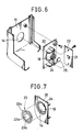
- an internal frame 20 serving as the supporting member according to the present invention is fixed by screws to an inside surface of the interface cover 11, and a PCB (printed circuit board) 22 is fixed by screws to a rear end of the internal frame 20.
- the internal frame 20 is integrally formed with a recessed wall portion 19 defining the information input hole 14 therein.
- a light receiving element 21 serving as the optical information receiving means according to the present invention is mounted on a front surface of the PCB 22. More specifically, the recessed wall portion 19 of the internal frame 20 is formed at its innermost end with a light transmitting hole 24 around which a protection filter 25 is mounted. The protection filter 25 is opposed to the light receiving element 21 on the PCB 22.
- Such a structure is shown in Figs. 2, 3, 6 and 7.
- an elastic member 23 serving as the light shutting out member according to the present invention is mounted between an inner circumferential surface of the recessed wall portion 19 of the internal frame 20 and the inside surface of the interface cover 11.
- the elastic member 23 formed of an elastic material such as rubber is comprised of a domed portion 23b formed with crossed slits 23a and an annular portion 23c integrally connected with an annular end of the domed portion 23b so as to be formed by connecting a small-diameter O-ring with a large-diameter O-ring.
- the annular portion 23c is comprised of a retaining portion 70 formed by the small-diameter O-ring for retaining the information input/output projection 16 of the handy terminal 2 when it is inserted in the information input hole 14, a mounting portion 71 formed by the large-diameter O-ring for mounting the domed portion 23c between the inner circumferential surface of the recessed wall portion 19 of the internal frame 20 and the inside surface of the interface cover 11, and a positioning groove 72 circularly formed between the retaining portion 70 and the mounting portion 71 for engaging a positioning projection 73 formed on the internal frame 20.
- the elastic member 23 is fixedly positioned by sandwiching the mounting portion 71 between the inside surface of the interface cover 11 and the internal frame 20, and engaging the positioning projection 73 of the internal frame 20 with the positioning groove 72.
- the crossed slits 23a of the domed portion 23b of the elastic member 23 are normally closed by an elastic force of the domed portion 23b, while when a pressure is applied to an inner surface of the domed portion 23b, the domed portion 23b is elastically deformed to open the crossed slits 23a. That is, as shown in Fig.
- the domed portion 23b of the elastic member 23 is urged to be elastically deformed to open the slits 23a, and simultaneously the information input/output projection 16 is elastically retained by the retaining portion 70 of the elastic member 23.
- the information input/output projection 16 is positioned in the information input hole 14 so that the input/output lens 26 of the information input/output projection 16 is exactly positioned in opposition to the light receiving element 21 on the PCB 22 through the light transmitting hole 24 and the protection filter 25 of the internal frame 20.
- the front surface 15a of the housing 15 is in abutment against the front surface 11a of the interface cover 11. Accordingly, the front surfaces 11a and 15a are so formed as to serve as abutment positioning means 74 and 74', respectively.
- a RAM 27 serving as the information storing means according to the present invention is connected to a CPU 30, and an optical reading portion 28 and a light emitting portion 29 located behind the input/output lens 26 in opposed relationship are also connected to the CPU 30. Furthermore, the keyboard 17 and the display 18 as mentioned above are connected to an input side and an output side of the CPU 30, respectively.
- a ROM 32 preliminarily storing an operation program and fixed data
- a RAM 33 for storing variable data
- a reset IC 34 for storing variable data
- an optical interface driver 35 is connected to a CPU 31 for carrying out total electrical control.
- the optical interface driver 35 constitutes photoelectric conversion means for converting an optical data received by the light receiving element 21 into an electrical signal.
- a driver 38, a thermal head 41 and an A/D converter 39 are connected to the I/O port 37.
- a pulse motor 40 for driving a platen (not shown) in a printer section (not shown) provided inside the printer cover 10 is connected to the driver 38.
- a sensor 42 for detecting a temperature data of the thermal head 41 in the printer section is connected to the A/D converter 39 through a switch 43 for selectively conducting the temperature data. Further, an output from a battery 44 is adjusted by a regulator 45 to be supplied to both the thermal head 41 and the driver 38.
- a control panel 46 of the printer body 3 is connected to the I/O port 37.
- the control panel 46 is constituted of a keyboard and an LED for indicating various operational conditions.
- the CPU 31, the I/O port 37, the driver 38 and the pulse motor 40 constitute a print control section 47.
- the information input/output projection 16 of the handy terminal 2 having stored information of various commodities is brought into engagement with the information input hole 14 of the printer body 3.
- a data transfer mode is selected by operating the keyboard 17, and a desired one of the commodity data stored in the RAM 27 is accessed.
- the desired commodity data thus accessed is output as an optical signal from the light emitting portion 29 of the handy terminal 2, and is received by the light receiving element 21 of the printer body 3.
- the optical signal is converted into an electrical signal by the optical interface driver 35, and the electrical signal is input into the CPU 31 which in turn controls to output a print signal to the thermal head 41 in the printer section.
- the thermal head 41 is driven according to the print signal, and the pulse motor 40 is operated in synchronism with the thermal head 41.
- a label sheet (not shown) is printed by the thermal head 41, and is fed to a predetermined position by the pulse motor 40.
- the contents of the data stored in the RAM 27 can be modified, or additional data can be stored into the RAM 27 by operating the keyboard 17 before transferring the commodity data from the handy terminal 2 to the printer body 3.
- the condition of such modification or addition of the data can be confirmed on the display 18 of the handy terminal 2.
- the data to be temporarily stored into the RAM 27 and then transferred from the handy terminal 2 to the printer body 3 may be input by operating the keyboard 17 rather than by reading a bar code.
- a commodity data input by the keyboard 17 and transferred to the printer body 3 is processed by a program as print commodity data creating means preliminarily stored in the ROM 32.
- the optical data transfer device 1 As described above, according to the optical data transfer device 1, as the commodity data is transferred by engaging the handy terminal 2 with the printer body 3, a cable as data transfer means for connecting the handy terminal 2 with the printer body 3 is not necessary, but both the components 2 and 3 can be individually operated, thereby contributing to the improvement in operation efficiency. Further, as the data transfer from the handy terminal 2 to the printer body 3 is carried out by optical communication, illumination for reading of a bar code can be utilized for the light emitting portion 29 for outputting of data. In this case, an optical system of a conventional handy terminal (not shown) can be utilized, so that the structure may be simplified and an increase in number of parts may be prevented.
- the input/output lens 26 is located at the front end of the information input/output projection 16, the operability in reading the information can be improved, and the operability in inserting the information input/output projection 16 into the information input hole 14 of the printer body 3 can also be improved.
- the information input/output projection 16 of the handy terminal 2 connected with the printer body 3 is elastically retained by the retaining portion 70 of the elastic member 23 in the information input hole 14, and the abutment positioning portion 74' as the front surface 15a of the housing 15 is in abutment against the abutment positioning portion 74 as the front surface 11a of the interface cover 11, thereby exactly positioning the information input/output projection 16 of the handy terminal 2. Therefore, an optical path for data transfer can be formed easily and very exactly, thereby obtaining a high S/N ratio. Additionally, as the handy terminal 2 is not required to be held by an operator's hand during transferring of the commodity data, the operability can be improved.
- the optical data transfer device 1 as the light receiving element 21 located behind the innermost end of the information input hole 14 of the printer body 3 is normally shutting out from an external light by the domed portion 23b of the elastic member 23, it is possible to prevent that optical noise will enter the light receiving element 21 from the opening of the information input hole 14 to cause malfunction of the printer body 3.
- the domed portion 23b of the elastic member 23 for shutting out the light receiving element 21 of the printer body 3 is opened at the slits 23a when a pressure is applied to the inner surface of the domed portion 23b, while when the pressure is removed, the domed portion 23b restores its original condition owing to its elasticity.
- the domed portion 23b of the elastic member 23 is automatically operated, thereby eliminating the need of special control and operation for the domed portion 23b.
- the domed portion 23b for shutting out the light receiving element 21 of the printer body 3 is integrally formed with the retaining portion 70 for retaining the information input/output projection 16 of the handy terminal 2 to construct the elastic member 23. Accordingly, the number of parts and the number of manufacturing steps can be reduced to thereby improve the productivity.
- the elastic member 23 can be easily positioned by simply mounting the internal frame 20 on the inner surface of the interface cover 11 with the elastic member 23 sandwiched therebetween. Accordingly, also from this viewpoint, the productivity can be improved. Further, owing to the domed shape of the domed portion 23b of the elastic member 23, a relatively large restoring force in a closing direction of the slits 23a is generated. Accordingly, separation of the slits 23a due to fatigue of the domed portion 23b by repeated use can be prevented.
- the printer body 3 is provided with the shoulder belt 4 and the handles 6 so as to be used in various circumstances.
- the printer body 3 may be suspended from an operator's shoulder with the shoulder belt 4 to carry out the label issuing operation.
- the handles 6 are provided on the opposite side surfaces of the printer body 3, and the shoulder belt 4 is provided on the upper surface of the printer body 3, the control panel 46 can be readily operated without hindrance of the handles 6 if it is located on the upper surface of the printer body 3.
- the optical data transfer device 1 is intended to be applied to a bar code system, it is to be noted that the present invention is not limited to the above system.
- the data processing device may be constructed as a cash register, and a sales data to be stored into the handy terminal may be transferred to the cash register.
- the structure of the information input/output projection 16 of the handy terminal 2 in the optical data transfer device 1 is of a stepped tapering form such that a circular cone is connected with a cylinder
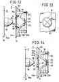
- a modification of the structure may be made as shown in Figs. 10 and 11, wherein the outer peripheral surface of an information input/output projection 48 of a handy terminal 49 is curved to gradually taper toward the front end thereof.
- a retaining member 50 for engageably retaining the information input/output projection 16 of the handy terminal 2 is mounted at the opening of the information input hole 14.
- Four pieces of sectoral plate-like light shutting out members 51 are provided in the information input hole 14 and pivotably mounted to respective hinges 52 fixed to the inside surface of the interface cover 11. As shown in Fig. 13, the light shutting out members 51 are arranged under the closed condition such that all the adjacent radii of the sectoral light shutting out members 51 are in close contact with each other.
- a spring 53 for biasing each light shutting out member 51 in a closing direction thereof is interposed under compression between each light shutting out member 51 and the internal frame 20.
- the light suhtting out members 51 are urged by the information input/output projection 16 to rotate about the hinges 52 and thereby open against the biasing force of the springs 53. Accordingly, data transfer from the handy terminal 2 to the printer body 3 can be carried out. Thereafter, when the information input/output projection 16 is removed from the information input hole 14, the light shutting out members 51 are closed by the biasing force of the springs 53, thus preventing entry of optical noise into the light receiving element 21.
- the spring 53 may be replaced by a leaf spring as shown in Fig. 14. That is, sectoral light shutting out members 61 are provided in the information input hole 14. Each light shutting out member 61 is integrally formed with a fixing portion 61a fixedly sandwiched between the interface cover 11 and the internal frame 20, a light shutting out portion 61b opposed to the opening of the information input hole 14, and a spring portion 61c as the leaf spring formed between the fixing portion 61a and the light shutting out portion 61b.
- the spring portion 61c has a wall thickness smaller than that of the other portions so as to function as the leaf spring.
Landscapes
- Engineering & Computer Science (AREA)
- General Engineering & Computer Science (AREA)
- Theoretical Computer Science (AREA)
- Physics & Mathematics (AREA)
- General Physics & Mathematics (AREA)
- Human Computer Interaction (AREA)
- Electromagnetism (AREA)
- Computer Networks & Wireless Communication (AREA)
- Signal Processing (AREA)
- Optical Communication System (AREA)
- Cash Registers Or Receiving Machines (AREA)
Applications Claiming Priority (2)
| Application Number | Priority Date | Filing Date | Title |
|---|---|---|---|
| JP2001982A JP2920176B2 (ja) | 1990-01-09 | 1990-01-09 | 光学式データ転送装置 |
| JP1982/90 | 1990-01-09 |
Publications (2)
| Publication Number | Publication Date |
|---|---|
| EP0437116A2 true EP0437116A2 (de) | 1991-07-17 |
| EP0437116A3 EP0437116A3 (en) | 1992-12-02 |
Family
ID=11516718
Family Applications (1)
| Application Number | Title | Priority Date | Filing Date |
|---|---|---|---|
| EP19900314454 Ceased EP0437116A3 (en) | 1990-01-09 | 1990-12-31 | Optical data transfer device |
Country Status (4)
| Country | Link |
|---|---|
| US (1) | US5105071A (de) |
| EP (1) | EP0437116A3 (de) |
| JP (1) | JP2920176B2 (de) |
| KR (1) | KR940005172B1 (de) |
Cited By (2)
| Publication number | Priority date | Publication date | Assignee | Title |
|---|---|---|---|---|
| FR2689274A1 (fr) * | 1992-03-26 | 1993-10-01 | Gemplus Card Int | Crayon à détection pour la saisie d'informations et système de saisie comportant un tel crayon. |
| EP0924636A3 (de) * | 1997-12-19 | 2002-10-16 | A.T.X. International, Inc. | Datenträger- und Stifthaltergerät |
Families Citing this family (3)
| Publication number | Priority date | Publication date | Assignee | Title |
|---|---|---|---|---|
| US5519527A (en) * | 1992-07-17 | 1996-05-21 | Milltronics Ltd. | Modem for communicating with enclosed electronic equipment |
| US6119944A (en) * | 1997-02-03 | 2000-09-19 | Symbol Technologies, Inc. | Down-loadable hand-held optical reader |
| JP2002023899A (ja) * | 2000-07-11 | 2002-01-25 | Furukawa Electric Co Ltd:The | 光通信可能な電子機器とそれに使用可能な光部品 |
Family Cites Families (7)
| Publication number | Priority date | Publication date | Assignee | Title |
|---|---|---|---|---|
| DE2734522A1 (de) * | 1977-07-30 | 1979-02-15 | Bosch Gmbh Robert | Optischer strahlungsschutz |
| DE2816325A1 (de) * | 1978-04-14 | 1979-10-18 | Computer Ges Konstanz | Einrichtung zum abtasten von mustern mit einer geregelten lichtquelle |
| SE419908B (sv) * | 1980-01-17 | 1981-08-31 | Micronic Ab | Kommunikationslenk |
| US4570057A (en) * | 1981-12-28 | 1986-02-11 | Norand Corporation | Instant portable bar code reader |
| FR2583546B1 (fr) * | 1985-06-14 | 1989-08-04 | Tourette Andre | Procede pour etablir une facture de produits pharmaceutiques suite a la delivrance d'une ordonnance |
| US4970379A (en) * | 1987-04-30 | 1990-11-13 | Norand Corporation | Bar code scanner system and scanner circuitry therefor |
| JPH0289522A (ja) * | 1988-09-27 | 1990-03-29 | Fujitsu Ltd | 板金曲げ加工方法 |
-
1990
- 1990-01-09 JP JP2001982A patent/JP2920176B2/ja not_active Expired - Lifetime
- 1990-12-22 KR KR1019900021423A patent/KR940005172B1/ko not_active Expired - Fee Related
- 1990-12-31 EP EP19900314454 patent/EP0437116A3/en not_active Ceased
-
1991
- 1991-01-04 US US07/637,630 patent/US5105071A/en not_active Expired - Fee Related
Cited By (2)
| Publication number | Priority date | Publication date | Assignee | Title |
|---|---|---|---|---|
| FR2689274A1 (fr) * | 1992-03-26 | 1993-10-01 | Gemplus Card Int | Crayon à détection pour la saisie d'informations et système de saisie comportant un tel crayon. |
| EP0924636A3 (de) * | 1997-12-19 | 2002-10-16 | A.T.X. International, Inc. | Datenträger- und Stifthaltergerät |
Also Published As
| Publication number | Publication date |
|---|---|
| KR940005172B1 (ko) | 1994-06-11 |
| JP2920176B2 (ja) | 1999-07-19 |
| US5105071A (en) | 1992-04-14 |
| EP0437116A3 (en) | 1992-12-02 |
| JPH03207131A (ja) | 1991-09-10 |
| KR910015136A (ko) | 1991-08-31 |
Similar Documents
| Publication | Publication Date | Title |
|---|---|---|
| US6916128B1 (en) | Printer attachable to various models and types of portable devices and terminals for operation therewith | |
| US5345090A (en) | Manual check reader apparatus with optical imaging | |
| US20230279694A1 (en) | Latch assemblies for portable electronic devices | |
| US10336112B2 (en) | Segmented enclosure | |
| US5163766A (en) | Printer device | |
| US5105071A (en) | Optical data transfer device | |
| CN107944315B (zh) | 移动成像条形码扫描仪 | |
| EP0416853B1 (de) | Etikett-Ausgabeapparat | |
| EP0490481B1 (de) | Elektronische Schreibmaschine | |
| US5486062A (en) | Printer-containing apparatus | |
| US6962448B2 (en) | Optical interlink between an optical transducer and optical data port | |
| US10384462B2 (en) | Easy replacement of thermal print head and simple adjustment on print pressure | |
| JP2529479Y2 (ja) | プリンタ装置 | |
| US5254988A (en) | Data communication system with card mounting portion | |
| JP2002236871A (ja) | ガンタイプ光学スキャナ | |
| EP1054317B1 (de) | Vorrichtung für einen tragbaren Terminal in einen Datenverarbeitungssystem | |
| JPH06348653A (ja) | 小型電子機器 | |
| KR20200109573A (ko) | 휴대용 프린터 및 휴대용 프린터의 제어 방법 | |
| JP3076074B2 (ja) | 光学式データ転送装置 | |
| JPH04273198A (ja) | 電子機器 | |
| JP4824161B2 (ja) | ハンディターミナルの携帯用キャリアー | |
| JP2633736B2 (ja) | 光学式データ転送装置 | |
| JPH042248A (ja) | データ入出力装置 | |
| JPH08459U (ja) | 携帯式印刷装置 | |
| JPH03207130A (ja) | 光学式データ転送装置 |
Legal Events
| Date | Code | Title | Description |
|---|---|---|---|
| PUAI | Public reference made under article 153(3) epc to a published international application that has entered the european phase |
Free format text: ORIGINAL CODE: 0009012 |
|
| 17P | Request for examination filed |
Effective date: 19910102 |
|
| AK | Designated contracting states |
Kind code of ref document: A2 Designated state(s): BE DE ES FR GB |
|
| PUAL | Search report despatched |
Free format text: ORIGINAL CODE: 0009013 |
|
| AK | Designated contracting states |
Kind code of ref document: A3 Designated state(s): BE DE ES FR GB |
|
| 17Q | First examination report despatched |
Effective date: 19941208 |
|
| RAP1 | Party data changed (applicant data changed or rights of an application transferred) |
Owner name: KABUSHIKI KAISHA TEC |
|
| STAA | Information on the status of an ep patent application or granted ep patent |
Free format text: STATUS: THE APPLICATION HAS BEEN REFUSED |
|
| 18R | Application refused |
Effective date: 19960129 |