EP0437166A2 - Thermischer Unterbrecher und Widerstandsanordnung - Google Patents
Thermischer Unterbrecher und Widerstandsanordnung Download PDFInfo
- Publication number
- EP0437166A2 EP0437166A2 EP90630206A EP90630206A EP0437166A2 EP 0437166 A2 EP0437166 A2 EP 0437166A2 EP 90630206 A EP90630206 A EP 90630206A EP 90630206 A EP90630206 A EP 90630206A EP 0437166 A2 EP0437166 A2 EP 0437166A2
- Authority
- EP
- European Patent Office
- Prior art keywords
- holder
- base
- supports
- thermal cutoff
- resistor
- Prior art date
- Legal status (The legal status is an assumption and is not a legal conclusion. Google has not performed a legal analysis and makes no representation as to the accuracy of the status listed.)
- Withdrawn
Links
Images


Classifications
-
- H—ELECTRICITY
- H05—ELECTRIC TECHNIQUES NOT OTHERWISE PROVIDED FOR
- H05K—PRINTED CIRCUITS; CASINGS OR CONSTRUCTIONAL DETAILS OF ELECTRIC APPARATUS; MANUFACTURE OF ASSEMBLAGES OF ELECTRICAL COMPONENTS
- H05K1/00—Printed circuits
- H05K1/02—Details
- H05K1/0201—Thermal arrangements, e.g. for cooling, heating or preventing overheating
-
- H—ELECTRICITY
- H01—ELECTRIC ELEMENTS
- H01H—ELECTRIC SWITCHES; RELAYS; SELECTORS; EMERGENCY PROTECTIVE DEVICES
- H01H61/00—Electrothermal relays
- H01H61/02—Electrothermal relays wherein the thermally-sensitive member is heated indirectly, e.g. resistively, inductively
-
- H—ELECTRICITY
- H05—ELECTRIC TECHNIQUES NOT OTHERWISE PROVIDED FOR
- H05K—PRINTED CIRCUITS; CASINGS OR CONSTRUCTIONAL DETAILS OF ELECTRIC APPARATUS; MANUFACTURE OF ASSEMBLAGES OF ELECTRICAL COMPONENTS
- H05K1/00—Printed circuits
- H05K1/18—Printed circuits structurally associated with non-printed electric components
-
- H—ELECTRICITY
- H05—ELECTRIC TECHNIQUES NOT OTHERWISE PROVIDED FOR
- H05K—PRINTED CIRCUITS; CASINGS OR CONSTRUCTIONAL DETAILS OF ELECTRIC APPARATUS; MANUFACTURE OF ASSEMBLAGES OF ELECTRICAL COMPONENTS
- H05K2201/00—Indexing scheme relating to printed circuits covered by H05K1/00
- H05K2201/10—Details of components or other objects attached to or integrated in a printed circuit board
- H05K2201/10007—Types of components
- H05K2201/10022—Non-printed resistor
-
- H—ELECTRICITY
- H05—ELECTRIC TECHNIQUES NOT OTHERWISE PROVIDED FOR
- H05K—PRINTED CIRCUITS; CASINGS OR CONSTRUCTIONAL DETAILS OF ELECTRIC APPARATUS; MANUFACTURE OF ASSEMBLAGES OF ELECTRICAL COMPONENTS
- H05K2201/00—Indexing scheme relating to printed circuits covered by H05K1/00
- H05K2201/10—Details of components or other objects attached to or integrated in a printed circuit board
- H05K2201/10007—Types of components
- H05K2201/10181—Fuse
-
- H—ELECTRICITY
- H05—ELECTRIC TECHNIQUES NOT OTHERWISE PROVIDED FOR
- H05K—PRINTED CIRCUITS; CASINGS OR CONSTRUCTIONAL DETAILS OF ELECTRIC APPARATUS; MANUFACTURE OF ASSEMBLAGES OF ELECTRICAL COMPONENTS
- H05K2201/00—Indexing scheme relating to printed circuits covered by H05K1/00
- H05K2201/10—Details of components or other objects attached to or integrated in a printed circuit board
- H05K2201/10227—Other objects, e.g. metallic pieces
- H05K2201/10386—Clip leads; Terminals gripping the edge of a substrate
-
- H—ELECTRICITY
- H05—ELECTRIC TECHNIQUES NOT OTHERWISE PROVIDED FOR
- H05K—PRINTED CIRCUITS; CASINGS OR CONSTRUCTIONAL DETAILS OF ELECTRIC APPARATUS; MANUFACTURE OF ASSEMBLAGES OF ELECTRICAL COMPONENTS
- H05K2201/00—Indexing scheme relating to printed circuits covered by H05K1/00
- H05K2201/10—Details of components or other objects attached to or integrated in a printed circuit board
- H05K2201/10431—Details of mounted components
- H05K2201/10507—Involving several components
- H05K2201/10537—Attached components
-
- H—ELECTRICITY
- H05—ELECTRIC TECHNIQUES NOT OTHERWISE PROVIDED FOR
- H05K—PRINTED CIRCUITS; CASINGS OR CONSTRUCTIONAL DETAILS OF ELECTRIC APPARATUS; MANUFACTURE OF ASSEMBLAGES OF ELECTRICAL COMPONENTS
- H05K3/00—Apparatus or processes for manufacturing printed circuits
- H05K3/30—Assembling printed circuits with electric components, e.g. with resistors
- H05K3/301—Assembling printed circuits with electric components, e.g. with resistors by means of a mounting structure
Definitions
- This application relates to the art of electric circuit component assemblies and, more particularly, to assemblies of components used for circuit protection.
- the invention is particularly applicable to arrangements for holding thermal cutoffs and to assembling same with heating resistors.
- certain features of the invention have broader aspects and can be used for other purposes.
- Thermal cutoffs are commonly combined with a resistance heater. In the event of a circuit malfunction, the resistance heater is energized for rapidly raising the thermal cutoff to a temperature at which it operates to provide an open circuit.
- a thermal cutoff and a resistor are assembled in adjacent side-by-side heat transfer relationship with one another.
- the thermal cutoff and resistor are held in assembled heat transfer relationship with one another by a metal clip.
- the thermal cutoff and resistor are held in physical contact with one another by the metal clip.
- a portion of the metal clip is interposed between the thermal cutoff and resistor.
- Each of the thermal cutoff and resistor have leads which may be specially shaped to provide a standoff for supporting the assembly above a printed circuit board.
- the metal clip used to hold the thermal cutoff and resistor in assembled relationship may be shaped to provide standoffs for holding the assembly spaced from the surface of a printed circuit board.
- a thermal grease may be provided between the thermal cutoff and resistor for enhancing heat transfer from the resistor to the thermal cutoff.
- a holder of dielectric material is preferably provided for holding the assembled thermal cutoff and resistor.
- the holder includes a base and a pair of spaced-apart supports extending outwardly from one side of such base.
- the supports have terminal end portions having lead receiving means for receiving and supporting leads on a thermal cutoff to hold such cutoff suspended between the supports. Holes through the base adjacent the supports receive the leads on a thermal cutoff.
- the holder preferably includes abutment means thereon for engagement by an assembled thermal cutoff and resistor to prevent rotation of such assembly relative to the holder.
- a large hole may be provided through the holder base in alignment with the assembled resistor and thermal cutoff for minimizing heat transfer from such assembly to the holder base.
- the holder base may also be provided with a cover.
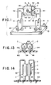
- Figure 1 shows a holder A of dielectric material.
- An assembly B of a thermal cutoff C, resistor D and metal clip E is adapted to be mounted on and held by holder A.
- Holder A includes a base 10 having a pair of spaced-apart supports 12, 14 extending outwardly from one side thereof. Supports 12, 14 have terminal end portions with lead receiving means 16, 18 in the form of keyhole slots. Holes 20, 21 extend through base 10 on opposite sides of support 12, and holes 22, 23 extend through base 10 on the opposite sides of support 14.
- Thermal cutoff C includes a cylindrical main body portion 30 having a pair of leads 32, 34 extending outwardly from the opposite ends thereof.
- Thermal cutoff C may take many forms, and may be of the type disclosed in US patent No. 4 808 960 issued February 28, 1989, the disclosure of which is hereby incorporated herein by reference.
- the thermal cutoff includes normally closed contacts, one of which is movable and biased to a closed position by a spring acting against a meltable thermal pellet. When the pellet melts, the force of the spring is substantially reduced and overcome by the force of a second spring biasing the movable contact in an open direction.
- Resistor D includes an elongated cylindrical main body 40 having leads 42, 44 extending outwardly from the opposite ends thereof.
- Resistor D may be of a conventional type such as a wire wound or metal film resistor in which a resistance wire or film is provided on a ceramic tube and encapsulated in a dielectric ceramic coating having a high thermal transfer coefficient.
- Metal clip E is preferably of beryllium copper to provide good heat transfer from resistor D to thermal cutoff C.
- Clip E is generally U-shaped in an end view, and includes a substantially flat base portion 50 having a pair of curved arms extending therefrom and toward one another. Arms 52, 54 have a curvature that is approximately the same or slightly smaller than the curvature of bodies 30, 40 of thermal cutoff C and resistor D. Arms 52, 54 terminate in outwardly curved end portions 56, 58 to facilitate snapping one of the thermal cutoff or resistor into the clip once one is already in position.
- the distance between arms 52, 54 is preferably less than the combined diameters of bodies 30, 40 of thermal cutoff C and resistor D. Thus, arms 52, 54 will be under bending stress when the thermal cutoff and resistor are received therein, and will bias the thermal cutoff and resistor into firm physical engagement with one another for optimum heat transfer.
- thermal cutoff and resistor could be of different sizes
- the preferred arrangement has a thermal cutoff and resistor whose main body portions 30, 40 have approximately the same diameter. This simplifies manufacture of the clip and also simplifies assembly of the components into the clip. Body 40 of resistor D will generally be up to around 15 % longer than body 30 of thermal cutoff C in order to provide the desired wattage for the resistor.
- Thermal cutoff C and resistor D make line contact with one another in an engagement area that is spaced outwardly from base 50 of clip E.
- Base 50 of clip E has a central hole 60 therethrough aligned with such engagement area for providing access to the space between clip base 50 and the engagement area of the thermal cutoff and resistor.
- the defined space may be filled with a thermal grease by injecting same through hole 60.
- the thermal grease may be of any conventional type, such as a silicone grease filled with a ceramic powder to provide good heat transfer characteristics.
- thermal cutoff leads 32, 34 extend through holes 20, 23 in base 10, while resistor leads 42, 44 extend through holes 21, 22 in base 10.
- assembly B is suspended between supports 12, 14 spaced slightly above base 10.
- Thermal cutoff C is preferably located above resistor D to enhance heat transfer from the resistor to the thermal cutoff. Heat is transferred from resistor D to thermal cutoff C by conduction, convection and radiation. The metal clip and thermal grease optimize heat conduction from the resistor to the thermal cutoff.
- FIGS 2-4 show a preferred holder H molded in one piece of dielectric material, such as a glass filled polyamide.
- Holder H includes a generally rectangular base portion 70 having a pair of spaced-apart supports 72, 74 extending outwardly from one side thereof. Supports 72, 74 have terminal end portions with central lead receiving means 76, 78 thereon.
- lead receiving means 78 includes a generally circular hole 80 having a diameter approximately the same as or slightly greater than the diameter of a lead on a thermal cutoff to be assembled to the holder.
- a narrowed entrance 82 to hole 80 has a width that is smaller than the diameter of the hole and slightly smaller than the diameter of the leads on the thermal cutoff so that a lead snaps through narrowed entrance opening 82 into hole 80.
- Lead receiving means 78 diverges upwardly from narrowed entrance opening 82 for automatically guiding a lead toward hole 80.
- Lead receiving means 76 on support 72 is similarly shaped.
- Continuous narrow walls 90, 92 extend upwardly from base portion 70 adjacent the long sides thereof for stiffening base portion 70 against bending. Such continuous walls also project downwardly below bottom surface 94 of base portion 70 to define opposite elongated legs 96, 98 which are positionable against the surface of a printed circuit board for supporting bottom surface 94 of base portion 70 above the board.
- Holes 102, 103 extend through base portion 70 on opposite sides of support 72.
- Holes 104, 105 extend through base portion 70 on opposite sides of support 74.
- Each hole has a generally frusto-conical or funnel-shaped chamfer concentric therewith on the upper surface of base portion 70 for guiding leads through the holes.
- a central rectangular opening 108 is formed through base portion 70, and is also centrally located between supports 72, 74. As shown in Figure 2, opening 108 extends through at least one-half the width of base portion 70 measured in a direction perpendicular to walls 90, 92. Opening 108 has a length measured parallel to walls 90, 92 that is at least one-third of the distance between supports 72, 74. Abutment means 110, 112 extends upwardly and inwardly from walls 90, 92 at diagonally opposite corners of rectangular opening 108. When an assembly B of Figure 1 is supported on holder H, resistor D and the bottom portion of clip E are closely received between abutment means 110, 112 to prevent rotation of assembly B about the thermal cutoff leads that suspend the assembly from supports 72, 74.
- Figures 5-7 show assembly B mounted on holder H. If a hole in a printed circuit board is slightly misaligned with respect to one or more of holes 102-105 in base portion 70, spacing bottom surface 94 of base portion 70 above the printed circuit board allows the leads on the thermal cutoff and resistor to be bent slightly laterally between the printed circuit board and bottom surface 94 to accommodate such misalignment and to allow cleaning of flux after soldering to the circuit board.
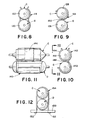
- Figures 8-14 show other clip arrangements for use with thermal cutoffs and resistors having approximately the same diameter.
- Figure 8 shows a generally U-shaped clip 118 having first and second arcuate portions 120, 122 whose centre lines are spaced-apart a distance slightly less than the diameter of the thermal cutoff or resistor.
- the curvature of the arcuate portions is slightly less than the curvature of the thermal cutoff and resistor. This arrangement causes the thermal cutoff and resistor to be firmly gripped resiliently and to be biased into good heat transfer engagement with one another.
- Figure 9 shows an arrangement wherein a clip 124 is generally S-shaped in an end view to provide oppositely facing arcuate portions 126, 128 whose center lines are spaced-apart a distance slightly less than the diameter of a thermal cutoff or resistor.
- a thermal cutoff C and resistor D are firmly gripped in arcuate portions 126, 128, a portion 130 of clip 124 is interposed between same in good heat transfer relationship therewith.
- clip 140 has an arcuate portion 142 for tightly gripping resistor D and has a finger 144 bent outwardly therefrom to define a second arcuate portion 146 in which thermal cutoff C is firmly gripped.
- the arcuate portions are shaped such that both the thermal cutoff and resistor are biased toward one another and into engagement with a portion 148 of finger 144.
- Figure 12 shows a flat base 150 having suitable spaced holes therethrough for receiving hooked ends 152 on a clip 154 in which thermal cutoff C and resistor D are resiliently held.
- Figure 13 shows a portion of a printed circuit board 160 having suitable holes therein for receiving leads 34, 44 on thermal cutoff C and resistor D.
- Clip 162 is shaped to firmly resiliently grip thermal cutoff C and resistor D, and to bias same into firm engagement with one another.
- Clip E has terminal standoff portions 164 for engaging the surface of printed circuit board 160 and holding thermal cutoff C and resistor D spaced outwardly from such surface of the board.
- Figure 14 shows an arrangement wherein clip E of Figure 1 holds thermal cutoff C and resistor D in good heat transfer relationship with one another.
- clip E of Figure 1 holds thermal cutoff C and resistor D in good heat transfer relationship with one another.
- the longitudinal axes of the thermal cutoff and resistor extending generally parallel to the printed circuit board, they extend generally perpendicular thereto.
- the terminal end portions of leads 32, 34 and 42, 44 are bent laterally at right angles to define short horizontal standoff portions and are then again bent at right angles for reception in suitable holes in printed circuit board 160.
- the lateral standoff portions are capable of supporting the assembled thermal cutoff and resistor elevated above the printed circuit board.
- thermal cutoff and resistor without the use of a metal clip.
- the thermal cutoff and resistor can be potted together in heat transfer relationship using a potting compound having good thermal conductivity.
- weld or glue assembly B to a holder A or H.
- the arrangement shown and described is preferred because it does not require the use of any glue, solder or welds.
Landscapes
- Engineering & Computer Science (AREA)
- Microelectronics & Electronic Packaging (AREA)
- Details Of Resistors (AREA)
- Fuses (AREA)
Applications Claiming Priority (2)
| Application Number | Priority Date | Filing Date | Title |
|---|---|---|---|
| US464386 | 1983-02-07 | ||
| US07/464,386 US4968962A (en) | 1990-01-12 | 1990-01-12 | Thermal cutoff and resistor assembly |
Publications (2)
| Publication Number | Publication Date |
|---|---|
| EP0437166A2 true EP0437166A2 (de) | 1991-07-17 |
| EP0437166A3 EP0437166A3 (en) | 1992-07-08 |
Family
ID=23843740
Family Applications (1)
| Application Number | Title | Priority Date | Filing Date |
|---|---|---|---|
| EP19900630206 Withdrawn EP0437166A3 (en) | 1990-01-12 | 1990-11-29 | Thermal cutoff and resistor assembly |
Country Status (3)
| Country | Link |
|---|---|
| US (1) | US4968962A (de) |
| EP (1) | EP0437166A3 (de) |
| JP (1) | JPH0773791A (de) |
Cited By (1)
| Publication number | Priority date | Publication date | Assignee | Title |
|---|---|---|---|---|
| SG94710A1 (en) * | 1998-08-17 | 2003-03-18 | Chu Jhi Electronics Co Ltd | A molded locating device for electronic element |
Families Citing this family (21)
| Publication number | Priority date | Publication date | Assignee | Title |
|---|---|---|---|---|
| US5161091A (en) * | 1991-12-20 | 1992-11-03 | Therm-O-Disc, Incorporated | Packaging unit for an electrical assembly |
| US5204498A (en) * | 1991-12-30 | 1993-04-20 | Therm-O-Disc, Incorporated | Packaging assembly |
| US5644106A (en) * | 1994-10-11 | 1997-07-01 | Therm-O-Disc, Incorporated | Thermistor holder |
| DE19613077C2 (de) * | 1996-04-02 | 1999-10-14 | Patent Treuhand Ges Fuer Elektrische Gluehlampen Mbh | Schaltungsanordnung zum Betreiben von elektrischen Lampen, insb. freischwingender Halbbrückenwandler |
| DE19735546A1 (de) * | 1997-08-16 | 1999-02-18 | Daimler Benz Ag | Sicherungselement für elektrische Anlagen |
| US5844761A (en) * | 1997-11-24 | 1998-12-01 | Place, Iv; Oliver Rex | Device for circuit board power surge protection such as protection of telecommunication line cards from lightning and power cross conditions |
| US6111758A (en) * | 1998-06-19 | 2000-08-29 | Scientific-Atlanta, Inc. | Electronic component having alternate functionalities |
| TWI320300B (en) * | 2005-11-18 | 2010-02-01 | Dissipating heat device of fin-type | |
| JP4973053B2 (ja) * | 2006-07-27 | 2012-07-11 | 株式会社デンソー | 電子装置 |
| KR100936232B1 (ko) * | 2007-10-15 | 2010-01-11 | 이종호 | 전류퓨즈 기능을 겸비한 용융형 온도퓨즈 |
| JP4943359B2 (ja) * | 2008-03-05 | 2012-05-30 | 内橋エステック株式会社 | 保護素子 |
| US20100033295A1 (en) | 2008-08-05 | 2010-02-11 | Therm-O-Disc, Incorporated | High temperature thermal cutoff device |
| US10145574B2 (en) * | 2009-12-10 | 2018-12-04 | Component Hardware Group, Inc. | Vent port for a refrigerated cabinet |
| US8803042B2 (en) | 2010-11-05 | 2014-08-12 | Automatic Switch Company | Thermal protection device and method |
| CN103515041B (zh) | 2012-06-15 | 2018-11-27 | 热敏碟公司 | 用于热截止装置的高热稳定性丸粒组合物及其制备方法和用途 |
| KR101724786B1 (ko) * | 2013-01-21 | 2017-04-07 | 한온시스템 주식회사 | 전자클러치용 필드코일 어셈블리 |
| US9398701B2 (en) * | 2013-03-14 | 2016-07-19 | General Electric Company | Component holding structures, system, and method |
| JP6217265B2 (ja) * | 2013-09-12 | 2017-10-25 | 村田機械株式会社 | 画像形成装置 |
| DE102014105594A1 (de) * | 2014-04-17 | 2015-10-22 | Conti Temic Microelectronic Gmbh | Elektronisches system |
| US20200088245A1 (en) * | 2018-09-14 | 2020-03-19 | Hanon Systems | Clutch coil thermal fuse heat sink activation |
| FR3108463A1 (fr) * | 2020-03-19 | 2021-09-24 | Valeo Systemes Thermiques | Dispositif de chauffage électrique avec circuit imprimé comportant un élément de guidage |
Family Cites Families (9)
| Publication number | Priority date | Publication date | Assignee | Title |
|---|---|---|---|---|
| US2460903A (en) * | 1945-05-21 | 1949-02-08 | Mallory & Co Inc P R | Motor starting capacitor assembly |
| FR1030764A (fr) * | 1951-01-08 | 1953-06-17 | Valve de sécurité | |
| US2979554A (en) * | 1959-06-17 | 1961-04-11 | Bendix Corp | Insulated mounting clamp for electrical components |
| DE1223013B (de) * | 1964-03-12 | 1966-08-18 | Telefunken Patent | Halter fuer stabfoermige Bauelemente (Widerstaende, Kondensatoren) |
| US3614345A (en) * | 1969-11-17 | 1971-10-19 | Zyrotron Ind Inc | Thermal sensing device |
| US3924214A (en) * | 1970-08-10 | 1975-12-02 | Micro Devices Corp | Thermal limiter construction for one or more electrical circuits and method of making the same |
| US4495480A (en) * | 1981-12-17 | 1985-01-22 | Inresco, Inc. | Multipattern electric component connecting pin base plate mounting assembly |
| US4808960A (en) * | 1987-11-06 | 1989-02-28 | Therm-O-Disc, Incorporated | Thermal cutoff heater |
| US4821010A (en) * | 1987-12-30 | 1989-04-11 | Therm-O-Disc, Incorporated | Thermal cutoff heater |
-
1990
- 1990-01-12 US US07/464,386 patent/US4968962A/en not_active Expired - Fee Related
- 1990-11-29 EP EP19900630206 patent/EP0437166A3/en not_active Withdrawn
- 1990-12-21 JP JP2413075A patent/JPH0773791A/ja active Pending
Cited By (1)
| Publication number | Priority date | Publication date | Assignee | Title |
|---|---|---|---|---|
| SG94710A1 (en) * | 1998-08-17 | 2003-03-18 | Chu Jhi Electronics Co Ltd | A molded locating device for electronic element |
Also Published As
| Publication number | Publication date |
|---|---|
| JPH0773791A (ja) | 1995-03-17 |
| EP0437166A3 (en) | 1992-07-08 |
| US4968962A (en) | 1990-11-06 |
Similar Documents
| Publication | Publication Date | Title |
|---|---|---|
| US4968962A (en) | Thermal cutoff and resistor assembly | |
| EP0215024B1 (de) | Mit lot versehenes kontaktelement | |
| EP0233136A2 (de) | Heizelementaufbau für Wassererhitzer | |
| US5716222A (en) | Ball grid array including modified hard ball contacts and apparatus for attaching hard ball contacts to a ball grid array | |
| EP0303873B1 (de) | Vorrichtung einer leitenden Verbindung | |
| EP0351985B1 (de) | Elektrischer Steckverbinder mit einem Lötmittel | |
| KR100771717B1 (ko) | 히터 어셈블리용 개선된 절연체 지지부 | |
| US5888102A (en) | Surface mount carrier for electronic components | |
| TW388037B (en) | NTC thermistor | |
| US5204498A (en) | Packaging assembly | |
| AU659855B2 (en) | Thermister device of positive characteristic | |
| EP0307067A2 (de) | Sicherungsabdeckungen | |
| WO1995024045A1 (en) | Thermistor | |
| US4926542A (en) | Method of making a surface mount wirewound resistor | |
| US4884053A (en) | Surface mount wirewound resistor and method of making the same | |
| US7018243B2 (en) | Connector | |
| US5644106A (en) | Thermistor holder | |
| EP0319450B1 (de) | Polymertyp-PTC-Anordnung | |
| JPH0349361Y2 (de) | ||
| US5161091A (en) | Packaging unit for an electrical assembly | |
| JP2509521Y2 (ja) | プリント板への部品取付け構造 | |
| CA1237495A (en) | Flexible light strip assembly | |
| JPS6233236Y2 (de) | ||
| JPH019070Y2 (de) | ||
| JPH08106965A (ja) | 接続具の取付け構成体 |
Legal Events
| Date | Code | Title | Description |
|---|---|---|---|
| PUAI | Public reference made under article 153(3) epc to a published international application that has entered the european phase |
Free format text: ORIGINAL CODE: 0009012 |
|
| AK | Designated contracting states |
Kind code of ref document: A2 Designated state(s): DE FR GB IT |
|
| PUAL | Search report despatched |
Free format text: ORIGINAL CODE: 0009013 |
|
| AK | Designated contracting states |
Kind code of ref document: A3 Designated state(s): DE FR GB IT |
|
| 17P | Request for examination filed |
Effective date: 19921230 |
|
| 17Q | First examination report despatched |
Effective date: 19940819 |
|
| STAA | Information on the status of an ep patent application or granted ep patent |
Free format text: STATUS: THE APPLICATION IS DEEMED TO BE WITHDRAWN |
|
| 18D | Application deemed to be withdrawn |
Effective date: 19941230 |