EP0437219A1 - Appareil de reproduction avec balayage hélicoidal pour données numériques - Google Patents
Appareil de reproduction avec balayage hélicoidal pour données numériques Download PDFInfo
- Publication number
- EP0437219A1 EP0437219A1 EP91100116A EP91100116A EP0437219A1 EP 0437219 A1 EP0437219 A1 EP 0437219A1 EP 91100116 A EP91100116 A EP 91100116A EP 91100116 A EP91100116 A EP 91100116A EP 0437219 A1 EP0437219 A1 EP 0437219A1
- Authority
- EP
- European Patent Office
- Prior art keywords
- ordinal number
- digital data
- data
- scan digital
- searching
- Prior art date
- Legal status (The legal status is an assumption and is not a legal conclusion. Google has not performed a legal analysis and makes no representation as to the accuracy of the status listed.)
- Granted
Links
- 238000004804 winding Methods 0.000 claims abstract description 9
- 238000001514 detection method Methods 0.000 claims description 14
- 230000004044 response Effects 0.000 claims description 13
- 238000000926 separation method Methods 0.000 claims description 3
- 238000010586 diagram Methods 0.000 description 4
- 230000006870 function Effects 0.000 description 4
- 230000005236 sound signal Effects 0.000 description 4
- 101150035718 Pno1 gene Proteins 0.000 description 2
- 230000003247 decreasing effect Effects 0.000 description 1
- 230000000694 effects Effects 0.000 description 1
- 238000012986 modification Methods 0.000 description 1
- 230000004048 modification Effects 0.000 description 1
Images


Classifications
-
- G—PHYSICS
- G11—INFORMATION STORAGE
- G11B—INFORMATION STORAGE BASED ON RELATIVE MOVEMENT BETWEEN RECORD CARRIER AND TRANSDUCER
- G11B27/00—Editing; Indexing; Addressing; Timing or synchronising; Monitoring; Measuring tape travel
- G11B27/10—Indexing; Addressing; Timing or synchronising; Measuring tape travel
-
- G—PHYSICS
- G11—INFORMATION STORAGE
- G11B—INFORMATION STORAGE BASED ON RELATIVE MOVEMENT BETWEEN RECORD CARRIER AND TRANSDUCER
- G11B27/00—Editing; Indexing; Addressing; Timing or synchronising; Monitoring; Measuring tape travel
- G11B27/02—Editing, e.g. varying the order of information signals recorded on, or reproduced from, record carriers
- G11B27/031—Electronic editing of digitised analogue information signals, e.g. audio or video signals
- G11B27/032—Electronic editing of digitised analogue information signals, e.g. audio or video signals on tapes
-
- G—PHYSICS
- G11—INFORMATION STORAGE
- G11B—INFORMATION STORAGE BASED ON RELATIVE MOVEMENT BETWEEN RECORD CARRIER AND TRANSDUCER
- G11B27/00—Editing; Indexing; Addressing; Timing or synchronising; Monitoring; Measuring tape travel
- G11B27/10—Indexing; Addressing; Timing or synchronising; Measuring tape travel
- G11B27/102—Programmed access in sequence to addressed parts of tracks of operating record carriers
- G11B27/107—Programmed access in sequence to addressed parts of tracks of operating record carriers of operating tapes
-
- G—PHYSICS
- G11—INFORMATION STORAGE
- G11B—INFORMATION STORAGE BASED ON RELATIVE MOVEMENT BETWEEN RECORD CARRIER AND TRANSDUCER
- G11B27/00—Editing; Indexing; Addressing; Timing or synchronising; Monitoring; Measuring tape travel
- G11B27/10—Indexing; Addressing; Timing or synchronising; Measuring tape travel
- G11B27/19—Indexing; Addressing; Timing or synchronising; Measuring tape travel by using information detectable on the record carrier
- G11B27/28—Indexing; Addressing; Timing or synchronising; Measuring tape travel by using information detectable on the record carrier by using information signals recorded by the same method as the main recording
- G11B27/30—Indexing; Addressing; Timing or synchronising; Measuring tape travel by using information detectable on the record carrier by using information signals recorded by the same method as the main recording on the same track as the main recording
- G11B27/3027—Indexing; Addressing; Timing or synchronising; Measuring tape travel by using information detectable on the record carrier by using information signals recorded by the same method as the main recording on the same track as the main recording used signal is digitally coded
-
- G—PHYSICS
- G11—INFORMATION STORAGE
- G11B—INFORMATION STORAGE BASED ON RELATIVE MOVEMENT BETWEEN RECORD CARRIER AND TRANSDUCER
- G11B27/00—Editing; Indexing; Addressing; Timing or synchronising; Monitoring; Measuring tape travel
- G11B27/10—Indexing; Addressing; Timing or synchronising; Measuring tape travel
- G11B27/19—Indexing; Addressing; Timing or synchronising; Measuring tape travel by using information detectable on the record carrier
- G11B27/28—Indexing; Addressing; Timing or synchronising; Measuring tape travel by using information detectable on the record carrier by using information signals recorded by the same method as the main recording
- G11B27/30—Indexing; Addressing; Timing or synchronising; Measuring tape travel by using information detectable on the record carrier by using information signals recorded by the same method as the main recording on the same track as the main recording
- G11B27/3027—Indexing; Addressing; Timing or synchronising; Measuring tape travel by using information detectable on the record carrier by using information signals recorded by the same method as the main recording on the same track as the main recording used signal is digitally coded
- G11B27/3036—Time code signal
-
- G—PHYSICS
- G11—INFORMATION STORAGE
- G11B—INFORMATION STORAGE BASED ON RELATIVE MOVEMENT BETWEEN RECORD CARRIER AND TRANSDUCER
- G11B27/00—Editing; Indexing; Addressing; Timing or synchronising; Monitoring; Measuring tape travel
- G11B27/10—Indexing; Addressing; Timing or synchronising; Measuring tape travel
- G11B27/19—Indexing; Addressing; Timing or synchronising; Measuring tape travel by using information detectable on the record carrier
- G11B27/28—Indexing; Addressing; Timing or synchronising; Measuring tape travel by using information detectable on the record carrier by using information signals recorded by the same method as the main recording
- G11B27/32—Indexing; Addressing; Timing or synchronising; Measuring tape travel by using information detectable on the record carrier by using information signals recorded by the same method as the main recording on separate auxiliary tracks of the same or an auxiliary record carrier
- G11B27/322—Indexing; Addressing; Timing or synchronising; Measuring tape travel by using information detectable on the record carrier by using information signals recorded by the same method as the main recording on separate auxiliary tracks of the same or an auxiliary record carrier used signal is digitally coded
- G11B27/324—Duty cycle modulation of control pulses, e.g. VHS-CTL-coding systems, RAPID-time code, VASS- or VISS-cue signals
-
- G—PHYSICS
- G11—INFORMATION STORAGE
- G11B—INFORMATION STORAGE BASED ON RELATIVE MOVEMENT BETWEEN RECORD CARRIER AND TRANSDUCER
- G11B2220/00—Record carriers by type
- G11B2220/90—Tape-like record carriers
-
- G—PHYSICS
- G11—INFORMATION STORAGE
- G11B—INFORMATION STORAGE BASED ON RELATIVE MOVEMENT BETWEEN RECORD CARRIER AND TRANSDUCER
- G11B2220/00—Record carriers by type
- G11B2220/90—Tape-like record carriers
- G11B2220/91—Helical scan format, wherein tracks are slightly tilted with respect to tape direction, e.g. VHS, DAT, DVC, AIT or exabyte
-
- G—PHYSICS
- G11—INFORMATION STORAGE
- G11B—INFORMATION STORAGE BASED ON RELATIVE MOVEMENT BETWEEN RECORD CARRIER AND TRANSDUCER
- G11B2220/00—Record carriers by type
- G11B2220/90—Tape-like record carriers
- G11B2220/91—Helical scan format, wherein tracks are slightly tilted with respect to tape direction, e.g. VHS, DAT, DVC, AIT or exabyte
- G11B2220/913—Digital audio tape [DAT] format
Definitions
- This invention relates to a helical scan digital data reproduce apparatus, and particularly relates to a helical scan digital data reproduce apparatus suited for a digital audio tape recorder and a PCM audio VTR.
- a digital audio tape recorder as a helical scan digital reproduce apparatus which can record a digital audio signal on a magnetic tape.
- searching a desired program is carried out by using an index signal, a program number, or a START-ID recorded at top of a program as similar to an index signal, which is one of ID codes.
- Such a prior art digital audio tape recorder using only index signal can search a desired data in accordance with index signal such as to search the desired program in accordance with a manually inputted an ordinal number from the present tape position. This is relative search.
- Such a recorder cannot perform absolute searching such as to search a program according to one program number indicating an ordinal number from the begin of the magnetic tape.
- the absolute search is possible when the ID cord is used.
- the PCM audio VTR it is difficult to read out the ID code except in reproducing mode. Therefore, the ID code cannot be used in the search mode wherein the recording medium is transferred at a high speed.
- This invention is developed to improve the above-mentioned problem and to perform the absolute searching according to the program number except in the reproduce mode.
- the present invention has been developed in order to remove the above-described drawbacks inherent to the conventional digital data reproduce apparatus.
- a helical scan digital data reproduce apparatus of the invention provides absolute searching of a desired program with the program numbers recorded on helical track during travelling a recording medium at a high seed in the fast-forward or rewinding mode because the apparatus calculates the program number by counting the index signals recorded on a fixed track during searching. If the program number has not been detected because just after putting a cassette tape, the apparatus once reproduce the magnetic tape to read the program number before winding the magnetic tape.
- a helical scan digital data reproduce apparatus for reproducing data from a magnetic recording medium, each of helically scanned tracks including a synchronizing signal, the data, and an ordinal number of plural trains of the data which is recorded at a given region of the one of said tracks at a start of each of the trains, an index signal being recorded on a control track at the start
- the apparatus having reproducing, searching modes: an input circuit for inputting the ordinal number of a desired train of the trains in response to a manual operation; a helical scanning head for reading out a synchronizing signal, the data, and the ordinal number from the magnetic recording medium; a synchronizing signal detection circuit responsive to output of the helical scanning head for detecting the synchronizing signal; a separation circuit responsive to the read synchronizing signal, the red data, and the ordinal number for separating an output of the helical scanning head into the data and the ordinal number in accordance with a given timing determined by the synchronizing; a control head for reading the
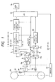
- Fig. 1 is a block diagram of an embodiment of a PCM audio VTR, as a helical scan digital data reproduce apparatus of the invention.
- a magnetic tape 31 is travelled by capstan 26 and wound by a take up reel 24.
- Digital data recorded along plural tracks made by helically scanning is reproduced by a pair of rotary heads 2 (only one is shown) which are actually mounted on the rotary cylinder 30.
- the reproduced signal by the head 2 is fed to an amplifier 4 through a switch 13a responsive to a record/reproduce signal 28.
- the amplified signal is applied to a PCM signal processing circuit 6 through switch 13b responsive to a record/reproduce mode switching signal 28.
- the PCM signal processing circuit 6 detects a synchronizing signal and separates the amplified reproduced digital data into data or audio signal 34 and ID codes in response the synchronizing signal.
- the synchronizing signal is recorded on the magnetic tape 31 at a beginning of each block in every field or track by specified code.
- ID code is recorded at given regions of the track. Thus, the ID code can be separated with reference to the synchronizing signal.
- ID codes separated by the PCM signal processing circuit 6 is sent to an ID code encode/decode circuit 8 for encoding the ID code.
- the encoded ID codes are sent to a program number detection/generating circuit 11 for detecting a program number with reference to the synchronizing signal.
- the program number is recorded on the magnetic tape in the region of the ID code at a given space.
- the program number can be detected by referring the synchronizing signal.
- the detected program number as an ordinal number of a data train is supplied to a microprocessing unit (mpu) 12.
- the magnetic tape 31 is also scanned by a fixed control head 16 for controlling tracking.
- An index signal of a program is recorded on the magnetic tape 31 by changing magnetizing pattern on the control track, for example duty ratio.
- the control signal reproduced by the control head 16 is sent to an index signal record/detecting circuit 20 through amplifier 18.
- the index signal record/detecting circuit 20 detects the index signal and sent it to the microprocessing unit 12.
- the record/reproduce mode switching signal 28 is produced by a microprocessing unit 12 in response to an input circuit 14 and changes the ID code encode/decode circuit, the program number detection/generation circuit 11, the index signal recording /detection circuit 20, and switches 17a and 17b between the reproduce and record modes.
- An input circuit 14 produces commands of reproduce, record, fast-winding, rewinding, and search modes and also produces a program number to be searched in response to manual operation.
- the microprocessing unit 12 sends a control signal 38 to a drive circuit 22 for driving the rotary cylinder 30, the capstan 26, the take-up reel 24 to perform the reproduce, record, fast-winding, rewinding, and search modes in accordance with a program stored therein.
- a control signal 38 to a drive circuit 22 for driving the rotary cylinder 30, the capstan 26, the take-up reel 24 to perform the reproduce, record, fast-winding, rewinding, and search modes in accordance with a program stored therein.
- Fig. 7 shows a signal recorded on the magnetic tape schematically.
- top portions of first two programs have respective interval portions where any audio signal is not substantially recorded.
- a top of the third program has no interval portion.
- the index number (ID code) is set to zero at the interval portion and then, is increased by one at given interval.
- the program start flag is set for a given interval just after a change of the index number to 1.
- the index signal is also produced for a given interval just after the change of the index number to 1.
- An initializing is made before start of the flow of Fig. 8. During initializing, a possible largest number is set to a variable of a program number.
- a program number to be searched is inputted by a user (step S1), as shown in Fig. 8.
- the microprocessing unit 12 checks whether the program number at the present tape position has been detected by checking whether the variable of the program number is a reasonable number. If NO, once the microprocessing unit 12 sets the system to the reproducing mode. Then, the magnetic tape 31 is reproduced by traveling it at a reproducing speed (steps S2 and S3). As the result, when the program number is detected, the apparatus is set into a stop mode (steps S2, S4, and S5). If YES in step S2, processing proceeds to step S5 where the stop mode is set to.
- step S6 the microprocessing unit 12 makes a decision as to whether the program number at the present tape position is greater than that of a searched program, or a desired program. If the program number for searching is greater than that of the present tape position, the magnetic tape 31 is travelled in the fast-forward mode in step S11. During this, when the index signal is detected is step S12, the program number as the present tape position is increased by one in step S13 and then, it is compared with the program number for searching in step S14. If the program number of the present tape position is not equal to the program number for searching, the fast-forward mode is continued.
- step S15 When both program numbers are equal to each other, rewinding at a low speed is executed in step S15 to return the magnetic tape 31 to a point just before an index signal (end point of a program just before the desired program to be searched) for correction of the overrun (steps S15 to S 17).
- Fig. 9 illustrates the above-mentioned operation with respect to the magnetic tape 31.
- step S6 if the program number for searching is smaller than or equal to that of the present tape position in step S6, the magnetic tape 31 is rewound in step S21.
- the program number of the present position is compared with that for searching in steps S22 and S23. If the program number of the present tape position is not equal to the program number for searching, the program number of the present position is decreased by one in step S24 and the rewinding is continued.
- step 23 the magnetic tape 31 is rewound to an end of an index signal (an end point of a program just before the desired program to be searched) in steps S25 to S26.
- Fig. 10 illustrates the above-mentioned operation with respect to the magnetic tape 31.
- Fig. 2 is a block diagram of a modified embodiment of the digital reproduce apparatus with recording function and shows recording the ID code and the index signal.
- the record/reproduce mode switching signal changes the system to the record mode.
- the rotary heads 2 record PCM digital data which is made by mixing data or the audio signal 34 with the ID code from the ID code encode/decode circuit 8 including the program number.
- the program number is generated by program number detection/generation circuit 11 in response to an output of the microprocessing unit 12.
- the microprocessing unit 12 produces an index signal which is recorded by the fixed control head 16 through the index signal record/detection circuit 20.
- the digital data reproduce apparatus with recording function can record a program after search operation shown in the flow of Fig. 8 to record a new program over a desired recorded program.
- the index signal record/detection circuit writes an index signal onto a magnetic tape 31 in response to an index signal write request command from the microprocessing unit 12.
- the index signal which has been used in the conventional VTR, is recorded by recording a control signal whose duty ratio is changed at a top portion of a program on the magnetic tape 31 by the control head in a control track.
- Fig. 3 schematically illustrates a track pattern on the magnetic tape of the modified embodiment of the digital data reproduce apparatus of the invention.
- PCM audio data and ID code are recorded on tracks of the magnetic tape 31 as shown in Fig. 3.
- Each track (field) is divided into five sub-frames.
- Each sub-frame is further divided into thirty blocks of address zero to twenty-nine, as shown in Fig. 4.
- Each block has a synchronizing signal region (8 bits), an address signal region (8 bits), an ID code region (8 bits), a parity check signal region (8bits) for error check of the address signal and the ID code, and a PCM audio data region (31 x 8 bits) in mentioned order.
- Fig. 5 shows a format for recording ID codes on respective blocks.
- An item (ITEM) of four bits and hundreds digit (PNO-1) of a program number can be recorded in the ID code regions of address 1 and address 17, as shown in Fig. 6.
- PNO-1 four bits and hundreds digit
- PNO-2 tens digit 2
- PNO-3 units digit
- an index number (eight bits) can be recorded.
- the ITEM (four bits) indicates that AC1 to AC4 show a program number and an index number when the ITEM is "0100".
- Respective digits PNO-1, PNO-2 and PNO-3 of a program number are expressed in binary coded decimal (BCD) system.
- Data in the ID code regions of these addresses 1, 3, 5, and 7 (17, 19, 21, and 23) make up data AC1 to AC4.
- Each of data AC1 to AC4 is recorded at least once a field (track).
- the program number expressed in 8-bit binary notation is recorded in address 9 and address 25.
- address 11 and address 27 an index number (four bits) and a program start flag PSF (one bit) are recorded in the former five bits.
- Absolute time showing absolute time from a start of recording on the magnetic tape is recorded in binary notation on the latter three bits of addresses 11 and 27 and in addresses 13, 29, and 15.
- the program number shows the ordinal number of programs and is a binary number.
- the index number expressed in 4-bit binary notation shows the index number in each program a binary number.
- the program start flag PSF (one bit) is provided to recognize start of each program by recording "1" for three hundred of frames at start of the program.
- a blank shown in Fig. 6 indicates an unused region.
- an index number can be used in stead of the program number. It is possible that the same program number is recorded over the magnetic tape 31 and at every change of programs the index number is changed and an index signal is recorded at the same time. This enables searching with the index number and the index signal.
- a start position specified by the program number and index number which is represented by absolute time from the start of the tape as TOC data, is recorded over the magnetic tape.
- the index signal is recorded. This provides searching using the TOC data to utilize the program number and the index number.
- This invention can be provided by the PCM circuit 32 and a program for the micro-computer in the mechanical control CPU circuit 34 at a low cost.
- this invention improves the apparatus in operation because searching is possible only detection of an absolute address.
Landscapes
- Engineering & Computer Science (AREA)
- Multimedia (AREA)
- Indexing, Searching, Synchronizing, And The Amount Of Synchronization Travel Of Record Carriers (AREA)
- Signal Processing For Digital Recording And Reproducing (AREA)
Applications Claiming Priority (2)
| Application Number | Priority Date | Filing Date | Title |
|---|---|---|---|
| JP778/90 | 1990-01-06 | ||
| JP2000778A JPH0770203B2 (ja) | 1990-01-06 | 1990-01-06 | デジタルデータ再生装置 |
Publications (2)
| Publication Number | Publication Date |
|---|---|
| EP0437219A1 true EP0437219A1 (fr) | 1991-07-17 |
| EP0437219B1 EP0437219B1 (fr) | 1996-06-12 |
Family
ID=11483162
Family Applications (1)
| Application Number | Title | Priority Date | Filing Date |
|---|---|---|---|
| EP91100116A Expired - Lifetime EP0437219B1 (fr) | 1990-01-06 | 1991-01-02 | Appareil de reproduction avec balayage hélicoidal pour données numériques |
Country Status (5)
| Country | Link |
|---|---|
| US (1) | US5274513A (fr) |
| EP (1) | EP0437219B1 (fr) |
| JP (1) | JPH0770203B2 (fr) |
| KR (1) | KR940009435B1 (fr) |
| DE (1) | DE69120095T2 (fr) |
Cited By (2)
| Publication number | Priority date | Publication date | Assignee | Title |
|---|---|---|---|---|
| EP0534798A3 (en) * | 1991-09-27 | 1993-06-30 | Matsushita Electric Industrial Co., Ltd. | Tape recorder |
| GB2253737B (en) * | 1991-02-06 | 1995-04-12 | Samsung Electronics Co Ltd | Program filing in video recorder |
Families Citing this family (8)
| Publication number | Priority date | Publication date | Assignee | Title |
|---|---|---|---|---|
| JP2769250B2 (ja) * | 1991-06-19 | 1998-06-25 | 三菱電機株式会社 | 磁気テープ再生装置 |
| US5471352A (en) * | 1992-07-21 | 1995-11-28 | Hitachi, Ltd. | Recording/playback apparatus in which head and tape are held in intermittent contact during rapid search |
| JP3431030B2 (ja) * | 1992-11-12 | 2003-07-28 | ソニー株式会社 | 再生装置および再生方法 |
| TW223171B (en) * | 1993-01-06 | 1994-05-01 | Sony Co Ltd | Playback method and device |
| US6181498B1 (en) * | 1994-01-20 | 2001-01-30 | Sony Corporation | Recording and reproducing apparatus, information signal recording and reproducing system and method of managing invalid area information |
| US5859737A (en) * | 1994-04-21 | 1999-01-12 | Sony Corporation | Magnetic recording and/or reproducing apparatus having a search pattern and data arranged in a longitudinal track for facilitating a high speed search |
| US6850773B1 (en) | 1999-10-21 | 2005-02-01 | Firooz Ghassabian | Antenna system for a wrist communication device |
| US6432077B1 (en) * | 2000-12-26 | 2002-08-13 | Sensormedics Corporation | Device and method for treatment of surface infections with nitric oxide |
Citations (6)
| Publication number | Priority date | Publication date | Assignee | Title |
|---|---|---|---|---|
| US3851116A (en) * | 1969-12-24 | 1974-11-26 | Ibm | Automatic magnetic tape information retrieval system with speed and position tape drive control |
| DE3016059A1 (de) * | 1979-04-27 | 1980-11-13 | Hitachi Ltd | Bandstellensucher fuer ein pcm-aufzeichnungs- und -wiedergabe-geraet |
| WO1984002221A1 (fr) * | 1982-11-30 | 1984-06-07 | George Saint | Dispositifs de stockage de donnees |
| EP0272130A2 (fr) * | 1986-12-19 | 1988-06-22 | Sony Corporation | Enregistrement de données |
| EP0323910A2 (fr) * | 1988-01-08 | 1989-07-12 | Hewlett-Packard Limited | Méthodes de recherche pour milieux d'enregistrement |
| EP0327188A2 (fr) * | 1988-01-08 | 1989-08-09 | Hewlett-Packard Limited | Méthode de stockage de données sur bande d'enregistrement |
Family Cites Families (8)
| Publication number | Priority date | Publication date | Assignee | Title |
|---|---|---|---|---|
| JPH0795390B2 (ja) * | 1985-08-07 | 1995-10-11 | 株式会社日立製作所 | 磁気記録再生装置の制御信号記録装置 |
| JP2629679B2 (ja) * | 1986-10-08 | 1997-07-09 | ソニー株式会社 | 再生装置 |
| JPS63187490A (ja) * | 1987-01-29 | 1988-08-03 | Toshiba Corp | ビデオテ−プレコ−ダの頭出しシステム |
| US5016119A (en) * | 1987-02-27 | 1991-05-14 | Sony Corporation | Video signal reproducing apparatus with two modes of keeping track of address |
| JPS63213189A (ja) * | 1987-03-02 | 1988-09-06 | Victor Co Of Japan Ltd | Vtrのデ−タ記録装置 |
| JP2567602B2 (ja) * | 1987-03-31 | 1996-12-25 | 三洋電機株式会社 | 回転ヘッド式テープレコーダーの高速サーチ方法 |
| JPH0192945A (ja) * | 1987-10-05 | 1989-04-12 | Mitsubishi Electric Corp | 記録再生制御方式 |
| JPH01320657A (ja) * | 1988-06-22 | 1989-12-26 | Sanyo Electric Co Ltd | 回転ヘッド式デイジタルオーデイオテープレコーダの高速サーチ方法 |
-
1990
- 1990-01-06 JP JP2000778A patent/JPH0770203B2/ja not_active Expired - Fee Related
- 1990-12-14 KR KR1019900020582A patent/KR940009435B1/ko not_active Expired - Fee Related
- 1990-12-31 US US07/636,456 patent/US5274513A/en not_active Expired - Lifetime
-
1991
- 1991-01-02 EP EP91100116A patent/EP0437219B1/fr not_active Expired - Lifetime
- 1991-01-02 DE DE69120095T patent/DE69120095T2/de not_active Expired - Fee Related
Patent Citations (6)
| Publication number | Priority date | Publication date | Assignee | Title |
|---|---|---|---|---|
| US3851116A (en) * | 1969-12-24 | 1974-11-26 | Ibm | Automatic magnetic tape information retrieval system with speed and position tape drive control |
| DE3016059A1 (de) * | 1979-04-27 | 1980-11-13 | Hitachi Ltd | Bandstellensucher fuer ein pcm-aufzeichnungs- und -wiedergabe-geraet |
| WO1984002221A1 (fr) * | 1982-11-30 | 1984-06-07 | George Saint | Dispositifs de stockage de donnees |
| EP0272130A2 (fr) * | 1986-12-19 | 1988-06-22 | Sony Corporation | Enregistrement de données |
| EP0323910A2 (fr) * | 1988-01-08 | 1989-07-12 | Hewlett-Packard Limited | Méthodes de recherche pour milieux d'enregistrement |
| EP0327188A2 (fr) * | 1988-01-08 | 1989-08-09 | Hewlett-Packard Limited | Méthode de stockage de données sur bande d'enregistrement |
Non-Patent Citations (5)
| Title |
|---|
| JP-A-01 320657*SANYO ELECTRIC CO,LTD.*26-12-1989 &PATENTS ABSTRACTS OF JAPAN, Vol.14,No.128 *P-1019* *4071*March 9,1990, * |
| PATENT ABSTRACTS OF JAPAN vol. 12, no. 331 (P-755)(3178) 07 September 1988, & JP-A-63 094494 (SONY CORP.) 25 April 1988, * |
| PATENT ABSTRACTS OF JAPAN vol. 12, no. 468 (P-797)(3315) 08 December 1988, & JP-A-63 187490 (TOSHIBA CORP.) 03 August 1988, * |
| PATENT ABSTRACTS OF JAPAN vol. 13, no. 329 (P-904)(3677) 25 July 1989, & JP-A-01 092945 (MITSUBISHI ELECTRIC CORP.) 12 April 1989, * |
| PATENT ABSTRACTS OF JAPAN vol. 13, no. 54 (P-824)(3402) 08 February 1989, & JP-A-63 244436 (SANYO ELECTRIC CO.,LTD.) 11 October 1988, * |
Cited By (2)
| Publication number | Priority date | Publication date | Assignee | Title |
|---|---|---|---|---|
| GB2253737B (en) * | 1991-02-06 | 1995-04-12 | Samsung Electronics Co Ltd | Program filing in video recorder |
| EP0534798A3 (en) * | 1991-09-27 | 1993-06-30 | Matsushita Electric Industrial Co., Ltd. | Tape recorder |
Also Published As
| Publication number | Publication date |
|---|---|
| KR940009435B1 (ko) | 1994-10-13 |
| EP0437219B1 (fr) | 1996-06-12 |
| JPH03205675A (ja) | 1991-09-09 |
| KR910014911A (ko) | 1991-08-31 |
| DE69120095D1 (de) | 1996-07-18 |
| US5274513A (en) | 1993-12-28 |
| JPH0770203B2 (ja) | 1995-07-31 |
| DE69120095T2 (de) | 1996-10-24 |
Similar Documents
| Publication | Publication Date | Title |
|---|---|---|
| US4939595A (en) | Digital audio tape record/play-back system for recording/playing back character data together with digital audio data | |
| KR940010145B1 (ko) | 기록 재생장치 | |
| US5432769A (en) | Apparatus for intermittently recording or reproducing variable length coded video data | |
| US5070419A (en) | Method and apparatus for recording and reproducing of a recording medium | |
| US5485447A (en) | High-speed data dubbing method | |
| US5155636A (en) | Apparatus and method for recording and reproducing digital data | |
| US5274513A (en) | Search system for helical scan digital data reproduction apparatus | |
| GB2131996A (en) | Data storage devices | |
| US5239428A (en) | Magnetic tape recording/reproducing apparatus and method | |
| EP0153410B1 (fr) | Appareil d'enregistrement et de reproduction de signaux | |
| EP0496565B1 (fr) | Appareil de reproduction de données numériques | |
| US5659400A (en) | Information signal recording device for recording main information signal with index signal for rapidly and accurately searching main information signal | |
| JPH05210894A (ja) | 記録されたテープ状の磁気記録担体を得るための装置、そのような装置によって得られる記録担体、及び記録担体を再生するための再生装置 | |
| US5016119A (en) | Video signal reproducing apparatus with two modes of keeping track of address | |
| US6452738B1 (en) | Magnetic recording apparatus and reproducing apparatus | |
| US5303091A (en) | Digital audio tape recorder for recording character data with digital data | |
| US6240242B1 (en) | Recording apparatus for recording moving image and still image | |
| KR970071468A (ko) | 테이프형 기록매체의 기록/재생장치 및 기록/재생방법 | |
| US5434715A (en) | Process and device for copying magnetic tapes containing both program material and control data | |
| US6188834B1 (en) | Device and method for recording and reproducing image information | |
| JP2550529B2 (ja) | 記録再生装置 | |
| JP3545234B2 (ja) | タイムラプスvtr | |
| JP3764489B2 (ja) | 磁気記録装置 | |
| JP3211249B2 (ja) | 情報記録装置 | |
| JP3211248B2 (ja) | 情報記録装置 |
Legal Events
| Date | Code | Title | Description |
|---|---|---|---|
| PUAI | Public reference made under article 153(3) epc to a published international application that has entered the european phase |
Free format text: ORIGINAL CODE: 0009012 |
|
| AK | Designated contracting states |
Kind code of ref document: A1 Designated state(s): DE FR GB |
|
| 17P | Request for examination filed |
Effective date: 19910524 |
|
| 17Q | First examination report despatched |
Effective date: 19940309 |
|
| GRAH | Despatch of communication of intention to grant a patent |
Free format text: ORIGINAL CODE: EPIDOS IGRA |
|
| GRAH | Despatch of communication of intention to grant a patent |
Free format text: ORIGINAL CODE: EPIDOS IGRA |
|
| GRAA | (expected) grant |
Free format text: ORIGINAL CODE: 0009210 |
|
| AK | Designated contracting states |
Kind code of ref document: B1 Designated state(s): DE FR GB |
|
| ET | Fr: translation filed | ||
| REF | Corresponds to: |
Ref document number: 69120095 Country of ref document: DE Date of ref document: 19960718 |
|
| PLBE | No opposition filed within time limit |
Free format text: ORIGINAL CODE: 0009261 |
|
| STAA | Information on the status of an ep patent application or granted ep patent |
Free format text: STATUS: NO OPPOSITION FILED WITHIN TIME LIMIT |
|
| 26N | No opposition filed | ||
| REG | Reference to a national code |
Ref country code: GB Ref legal event code: IF02 |
|
| PGFP | Annual fee paid to national office [announced via postgrant information from national office to epo] |
Ref country code: GB Payment date: 20061227 Year of fee payment: 17 |
|
| PGFP | Annual fee paid to national office [announced via postgrant information from national office to epo] |
Ref country code: DE Payment date: 20061229 Year of fee payment: 17 |
|
| PGFP | Annual fee paid to national office [announced via postgrant information from national office to epo] |
Ref country code: FR Payment date: 20070109 Year of fee payment: 17 |
|
| GBPC | Gb: european patent ceased through non-payment of renewal fee |
Effective date: 20080102 |
|
| PG25 | Lapsed in a contracting state [announced via postgrant information from national office to epo] |
Ref country code: DE Free format text: LAPSE BECAUSE OF NON-PAYMENT OF DUE FEES Effective date: 20080801 |
|
| REG | Reference to a national code |
Ref country code: FR Ref legal event code: ST Effective date: 20081029 |
|
| PG25 | Lapsed in a contracting state [announced via postgrant information from national office to epo] |
Ref country code: GB Free format text: LAPSE BECAUSE OF NON-PAYMENT OF DUE FEES Effective date: 20080102 |
|
| PG25 | Lapsed in a contracting state [announced via postgrant information from national office to epo] |
Ref country code: FR Free format text: LAPSE BECAUSE OF NON-PAYMENT OF DUE FEES Effective date: 20080131 |