EP0437223A2 - Cassette de support d'enregistrement optique - Google Patents
Cassette de support d'enregistrement optique Download PDFInfo
- Publication number
- EP0437223A2 EP0437223A2 EP91100140A EP91100140A EP0437223A2 EP 0437223 A2 EP0437223 A2 EP 0437223A2 EP 91100140 A EP91100140 A EP 91100140A EP 91100140 A EP91100140 A EP 91100140A EP 0437223 A2 EP0437223 A2 EP 0437223A2
- Authority
- EP
- European Patent Office
- Prior art keywords
- data
- laser
- optical
- medium
- layer
- Prior art date
- Legal status (The legal status is an assumption and is not a legal conclusion. Google has not performed a legal analysis and makes no representation as to the accuracy of the status listed.)
- Granted
Links
Images


Classifications
-
- G—PHYSICS
- G11—INFORMATION STORAGE
- G11B—INFORMATION STORAGE BASED ON RELATIVE MOVEMENT BETWEEN RECORD CARRIER AND TRANSDUCER
- G11B23/00—Record carriers not specific to the method of recording or reproducing; Accessories, e.g. containers, specially adapted for co-operation with the recording or reproducing apparatus ; Intermediate mediums; Apparatus or processes specially adapted for their manufacture
- G11B23/02—Containers; Storing means both adapted to cooperate with the recording or reproducing means
- G11B23/03—Containers for flat record carriers
- G11B23/0301—Details
- G11B23/0308—Shutters
-
- G—PHYSICS
- G11—INFORMATION STORAGE
- G11B—INFORMATION STORAGE BASED ON RELATIVE MOVEMENT BETWEEN RECORD CARRIER AND TRANSDUCER
- G11B7/00—Recording or reproducing by optical means, e.g. recording using a thermal beam of optical radiation by modifying optical properties or the physical structure, reproducing using an optical beam at lower power by sensing optical properties; Record carriers therefor
- G11B7/12—Heads, e.g. forming of the optical beam spot or modulation of the optical beam
- G11B7/135—Means for guiding the beam from the source to the record carrier or from the record carrier to the detector
- G11B7/1365—Separate or integrated refractive elements, e.g. wave plates
-
- G—PHYSICS
- G11—INFORMATION STORAGE
- G11B—INFORMATION STORAGE BASED ON RELATIVE MOVEMENT BETWEEN RECORD CARRIER AND TRANSDUCER
- G11B7/00—Recording or reproducing by optical means, e.g. recording using a thermal beam of optical radiation by modifying optical properties or the physical structure, reproducing using an optical beam at lower power by sensing optical properties; Record carriers therefor
- G11B7/24—Record carriers characterised by shape, structure or physical properties, or by the selection of the material
- G11B7/2403—Layers; Shape, structure or physical properties thereof
- G11B7/24035—Recording layers
- G11B7/24038—Multiple laminated recording layers
-
- G—PHYSICS
- G11—INFORMATION STORAGE
- G11B—INFORMATION STORAGE BASED ON RELATIVE MOVEMENT BETWEEN RECORD CARRIER AND TRANSDUCER
- G11B7/00—Recording or reproducing by optical means, e.g. recording using a thermal beam of optical radiation by modifying optical properties or the physical structure, reproducing using an optical beam at lower power by sensing optical properties; Record carriers therefor
- G11B7/24—Record carriers characterised by shape, structure or physical properties, or by the selection of the material
- G11B7/26—Apparatus or processes specially adapted for the manufacture of record carriers
Definitions
- the present invention relates to an optical data medium for recording and reproducing data by the use of laser beam and a method for making the same.
- the present invention also relates to a cassette casing for carrying the optical data medium.
- Optical data media in such forms as optical cards and disks are now commercially available today, with optical disks in particular widely distributed as compact discs and laser discs. Higher data densities are desirable for a variety of reasons, including the ability to make CDs smaller and to enable the recording of High Definition Television (HDTV) compatible video discs.
- HDMI High Definition Television
- a second method is a new method whereby a high density is proposed to be achieved using V-grooves in the optical disk, such as disclosed in U.S. Patent No. 4,569,038 issued February 4, 1986 to Nagashima et al.
- the capacity of the data that can be achieved on an optical disk using conventional technologies is considered.
- the disk diameter is approximately 86 mm, providing a data storage area with a radius of 25 mm to 41 mm. It is assumed that a 670 nm wavelength laser is used with a 0.55 NA objective lens. With a 0.8 ⁇ m track pitch (1.6 ⁇ m V-groove pitch) and 0.47 ⁇ m bit length, the unformatted single-side capacity is 1.1 Gbytes.
- a single-side formatted capacity of 550 Mb the same as a 12 cm CD, can be obtained, but this is currently the maximum limit.
- CDs, video discs, and similar optical discs are not housed in a cassette case as are floppy disks and other magnetic data media.
- the playback signal quality can still be degraded by oil and other foreign matter deposited on the surface by, for example, touching the surface with the fingers during disk loading and unloading.
- a cassette case typically has a shutter which remains closed and hides the disk surface at all times other than during playback, it is now considered necessary and preferable to house optical discs in a cassette case.
- the object of the present invention is therefore to provide an optical data medium for recording and/or reproducing data with a higher density.
- the object of the present invention is to provide a cassette case which houses the optical data medium.
- an optical data medium from which information recorded to the surface thereof is reproduced by focusing a laser thereon and reading the light reflected from the data surface comprises: a first transparent layer having a first and second surfaces, said second surface being a first data surface carrying data; a semi-transparent layer deposited on said second surface; a second transparent layer having a third and fourth surfaces, said third surface being held in contact with said semi-transparent layer and said fourth surface being a second data surface carrying data; and a reflection layer deposited on said fourth surface.
- a method for manufacture an optical data medium from which information recorded to the surface thereof is reproduced by focusing a laser thereon and reading the light reflected from the data surface comprises the steps of: forming a first transparent layer having a first and second surfaces, said second surface being a first data surface carrying data; forming a semi-transparent layer deposited on said second surface; forming a second transparent layer having a third and fourth surfaces, said third surface being held in contact with said semi-transparent layer and said fourth surface being a second data surface carrying data; and forming a reflection layer deposited on said fourth surface.
- a cassette case for an optical data medium comprises: a casing for accommodating an optical data medium; a shutter movably mounted on said casing and having a first window; and a transparent plate mounted in said first window.
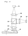
- FIG. 11 an optical system for recording and/or reproducing data on and/or from optical data medium of the present invention is shown.
- a laser beam emitted from a laser source 31 passes through a collimator 32 to produce parallel laser rays.
- the laser beam passing through a half mirror 33 is focused on an optical data medium M, such as an optical disk, by an objective lens 34.
- the optical data medium M has top and bottom data storing layers.
- a transparent plate 35 having a predetermined thickness and a predetermined refractive index is inserted in the laser beam pass, preferably between the objective lens 34 and the optical data medium M.
- a transparent plate 35 is removed.
- a laser beam reflected from the optical data medium M further reflects on the half mirror 33 and is focused on a detector 37 by a suitable lens assembly 36.
- the focus/defocus signal picked by the detector 37 is used for controlling the objective lens 34 so as to adjust the focusing condition of the laser beam on the optical data medium M. Also, the signal picked by the detector 37 is used for reproducing the data stored on the optical data medium M.
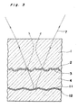
- an optical data medium M comprises two data storing layers of read-only type.
- reference number 1 is a transparent material layer 1 of glass or plastic, on one side of which is formed with data surface 2.
- data is written to the slopes of the V-grooves.
- Under data surface 2 is formed a semi-transparent thin film 3 to reflect only part of the incident laser.
- Under the semi-transparent thin film 3 is formed a transparent material layer 4, and on a lower surface of which is formed a data surface 5.
- a reflective film 6 non-transparent material film
- a protection layer 10 is provided on film 6.
- the optical data medium M of the first embodiment has the top data storing layer formed by top data surface 2 and thin film 3, and the bottom data storing layer formed by bottom data surface 5 and the film 6.
- Fig. 1 shows a case in which the laser beam 7 is focused on the bottom data surface 5 which is the farther one of the two data surfaces from the laser source.
- the data signal recorded on the bottom data face 5 can be reproduced because the laser 7 is focused on the data surface 5, but it should be noted that part of the laser as indicated by 7' is also reflected by the top data surface 2.
- the distance between the top and bottom data surfaces 2 and 5, in which the transparent material 4 is inserted is sufficiently large, such as 100 ⁇ m or greater, the diameter of the laser beam on the top data surface 2 is sufficiently large to prevent identification and reproduction of the signal recorded on the top data surface 2, and the playback signal from the data surface 5 is therefore not adversely affected.
- the semi-transparent thin film on the data surface 2 is formed uniformly, the incident laser is unaffected by local phase changes, and diffraction phenomena unsuitable to signal reproduction can be virtually ignored.
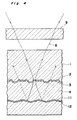
- Fig. 2 shows the case in which the laser beam 8 is focused on the top data surface 2 near the laser incidence side. Because the laser spot is focused on the top data surface 2, the data signal recorded thereto can be reproduced, but part of the laser also passes through the semi-transparent thin film 3 and is reflected by the bottom data surface 5. The reflected light is indicated by 8'. However, since the thickness of the transparent material layer 4 is sufficiently large, the diameter of the laser beam on the data surface 5 is sufficiently great, as in the first case described above. Thus, the signal recorded to the bottom data surface 5 cannot be identified and reproduced, and the playback signal from the top data surface 2 is therefore not adversely affected.
- the thickness of the transparent material between the objective lens and the data surface must be adjusted so that the product of the transparent material layer thickness and the refractive index is a value determined according to the objective lens.
- the refractive index of the disc substrate is approximately 1.5 and the thickness is 1.2 mm.
- the sum of the thickness of the two transparent material layers 1 and 4 must be selected in consideration of the specific thickness determined by the objective lens.
- the thickness of the transparent material layer between the objective lens 34 and the bottom data surface 5 to be read is the sum of the thicknesses of the two transparent material layers 1, 4, thereby enabling the laser to be sufficiently focused and making it possible to play back a high quality signal.
- a transparent plate 9 of a thickness which can absorb the deficiency in the optical path is inserted between the objective lens and the top data surface 2 when reading the top data surface 2.
- the data surface is described as provided two, but it is possible to provide more than two surfaces, as long as such data surfaces are spaced by a predetermined distance, such as 100 ⁇ m.
- the same principle applies when there are three or more layers.
- the reflectivity to the laser beam is reduced in each layer the closer the data surface is to the laser incidence side, thus enabling the laser to reach the data surface farthest from the laser incidence side for data reading. If the gap between differing data surfaces is made sufficiently large (e.g., more than 100 ⁇ m), the adverse affects of signals from data surfaces other than the one data surface being read can be ignored.
- the thickness of the transparent plate inserted between the objective lens and the disk needs only to be changed to maintain compatibility when reading from the data surfaces in three or more different layers.
- the optical data medium according to the second embodiment generally comprises a plurality of data surfaces, one of which can be read and written to by a laser while the remaining layers are read-only, so as not only to achieve a high data density and but also to enable the user to write new information at will.
- FIG. 3 shows the case in which the incident laser 7 is focused on the read/writable bottom data surface 11; and Fig. 4 shows the case in which the incident laser 8 is focused on the top data surface 2 nearest the laser incidence side.
- Like components in Figs. 1, 2, 3, and 4 are indicated by like reference numbers and further description thereof is herein omitted.
- the bottom data surface 11 is formed under the transparent material layer 4, and a recording layer 12 (non-transparent material film) is formed on the bottom data surface 11. Because information can be recorded by the user in this embodiment, there are no signal pits on the slopes of the V-grooves for data recording in the bottom data surface 11.
- the semi-transparent thin film 3 (non-transparent material film) is formed so that only part of the incident laser 7 is reflected. Therefore, the incident laser 7 can pass through the semi-transparent thin film 3 sufficiently, and reading from and writing to the recording layer 12 is therefore possible.
- the thickness of the transparent material layer 4 is sufficient as described in the first embodiment hereinabove, the diameter of the laser beam on the bottom data surface 11 when reading from the top data surface 2, and the diameter of the laser beam on the top data surface 2 when reading from the bottom data surface 11 is large enough, so that the signals from the other data surface do not adversely affect the signal being read from the one data surface.
- the thickness of the transparent material layer 4 is 100 ⁇ m or greater. Furthermore, if the semi-transparent thin film 3 under the top data surface 2 is formed uniformly, the incident laser is not affected by local phase changes, and diffraction phenomena unsuitable to signal reproduction can be virtually ignored.
- the local reflectance of the recording layer 12 varies at a place where the recording layer 12 is stored with data.
- the intensity distribution of the laser beam passing through the recording layer may be varied depending on the data written in the recording layer.
- the laser beam can not be sufficiently focused particularly when reproducing from the data surface furthest from the laser incidence side. Therefore, the read/writable recording layer should be formed at the furthest from the laser incidence side, and the read-only data surface should be formed nearest the laser incidence side.
- the sum of the thickness of the two transparent material layers 1 and 4 must be selected in consideration of the thickness determined by the objective lens focusing on the bottom data surface 11.
- the thickness between the objective lens and the read/write data surface is the sum of the thickness of the two transparent material layers 1 and 4, thereby enabling the laser to be sufficiently focused and making it possible to play back a high quality signal.
- a transparent plate 9 of a thickness which can absorb the deficiency in the optical path is inserted between the objective lens and the top data surface 2 when reading the top data surface 2.
- optical data medium comprising two layers was described hereinabove, but the same principle is true when there are three or more layers, in which case the data surface farthest from the laser incidence side is read/writable.
- the reflectivity to the laser beam is reduced in each layer the closer the data surface is to the laser incidence side, thus enabling the laser to reach the data surface farthest from the laser incidence side for data reading and writing. If the gap between differing data surfaces is made sufficiently large (e.g., 100 ⁇ m or more), the adverse affects of signals from data surfaces other than the one data surface being read can be ignored.
- the thickness of the transparent plate inserted between the objective lens and the disk needs only to be changed to reproduce the data from data surfaces in different layers.
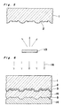
- reference number 1 is the transparent material layer on one side of which is formed with the data surface 2.
- the transparent material layer 1 can be formed with an injection molding process as used in CD and video disc replication.
- the semi-transparent thin film 3 is formed on the data surface 2 by vacuum deposition.
- Reference number 13 is the target material used for forming the semi-transparent thin film.
- a UV (ultraviolet ray) cured resin 15 is inserted between a stamper 14, which produces the data surface 5 shown in the first embodiment (the same is true when producing the data surface 11 in the second embodiment), and the semi-transparent thin film 3 formed on the data surface 2. Then, pressure is applied to obtain a predetermined thickness, and ultraviolet light 16 is applied through the transparent material layer 1 and the semi-transparent thin film 3 to cure the UV resin 15.
- a reflective film 6 (or recording layer 12) is formed by vacuum deposition on the data surface 5 (or data surface 11) thus formed.
- Reference number 17 is the target.
- An aluminum or other metallic material is used when forming the reflective film 6 in the first embodiment, and a phase change material or optomagnetic material is used when forming the recording layer 12 in the second embodiment.
- the protection layer 10 can be made in a manner similar to that described above by the use of UV cured resin.
- the semi-transparent thin film is a dielectric material with a refractive index that differs from the transparent material.
- laser reflection must decrease the closer the data surface is to the laser incidence side. This can be achieved by changing the thickness of the semi-transparent thin film to change the reflectivity of the layer.
- the thickness of the transparent material between the objective lens and the data surface must be a specific value.
- a plastic, glass, or other transparent plate is inserted between the objective lens and the disk surface. It is convenient if this transparent plate is inserted or removed therebetween by operating a shutter mechanism on the cassette case.
- This shutter is shown in Fig. 8, wherein 21 is a shutter comprising two windows: a window 22 in which nothing is inserted, and a window 24 in which a transparent plate 23 is inserted.
- the transparent plate 23 corresponds to the transparent plate 9 in the first and second embodiments, and is of a thickness to compensate for the thickness of the transparent material between the objective lens and the data surface.
- the shutter 21 is moved as shown in Fig. 9 to position the window 22 to which nothing is inserted between the objective lens and the disk.
- the shutter 21 is moved to position the window 24 to which the transparent plate 23 is inserted between the objective lens and the disk as shown in Fig. 10.
- the shutter With the cassette case for a floppy disk, the shutter is located in the direction of insertion as seen from the center of disk rotation. Specifically, the shutter moves perpendicularly to the direction of cassette insertion.
- the direction in which the cassette is inserted and the direction of shutter movement are parallel.
- Arrow X in Fig. 9 indicates the direction of cassette insertion.
- three or more windows shall be provided in the shutter with nothing inserted to one window as when the medium has two layers. Furthermore, transparent plates of different thicknesses are inserted to the other windows to compensate for the thickness of the transparent material between the objective lens and the data surface of the disk.
- the area of the data surface is increased, thus dramatically increasing the recording density, and making it possible to provide an area to which the user can write information without reducing the read-only area.
- optical data media as described above can be easily and simply manufactured.
- the laser can be sufficiently focused for the data surface in each layer, and because the media surface is not directly touched, a high quality signal can be read and written, and the cassette case can be manufactured at a low cost with a simple construction.
Landscapes
- Physics & Mathematics (AREA)
- Optics & Photonics (AREA)
- Engineering & Computer Science (AREA)
- Manufacturing & Machinery (AREA)
- Optical Recording Or Reproduction (AREA)
- Manufacturing Optical Record Carriers (AREA)
- Optical Head (AREA)
- Optical Record Carriers And Manufacture Thereof (AREA)
Applications Claiming Priority (2)
| Application Number | Priority Date | Filing Date | Title |
|---|---|---|---|
| JP2005826A JP2514261B2 (ja) | 1990-01-11 | 1990-01-11 | 光情報媒体、その製造方法、及びそのカセットケ―ス |
| JP5826/90 | 1990-01-11 |
Publications (3)
| Publication Number | Publication Date |
|---|---|
| EP0437223A2 true EP0437223A2 (fr) | 1991-07-17 |
| EP0437223A3 EP0437223A3 (en) | 1992-06-10 |
| EP0437223B1 EP0437223B1 (fr) | 1996-04-03 |
Family
ID=11621867
Family Applications (1)
| Application Number | Title | Priority Date | Filing Date |
|---|---|---|---|
| EP91100140A Expired - Lifetime EP0437223B1 (fr) | 1990-01-11 | 1991-01-04 | Cassette de support d'enregistrement optique |
Country Status (4)
| Country | Link |
|---|---|
| US (1) | US5134604A (fr) |
| EP (1) | EP0437223B1 (fr) |
| JP (1) | JP2514261B2 (fr) |
| DE (1) | DE69118409T2 (fr) |
Cited By (11)
| Publication number | Priority date | Publication date | Assignee | Title |
|---|---|---|---|---|
| EP0729142A1 (fr) * | 1995-02-27 | 1996-08-28 | Sony Corporation | Milieu d'enregistrement optique et son procédé de fabrication |
| WO1996031875A3 (fr) * | 1995-04-07 | 1996-11-21 | Matsushita Electric Industrial Co Ltd | Support optique d'enregistrement d'informations, procede de fabrication de ce support, equipement de fabrication et equipement optique d'enregistrement et de reproduction d'informations |
| EP0731459A3 (fr) * | 1995-03-10 | 1996-12-11 | Yeda Res & Dev | Méthode et appareil de stockage et de récupération pour disques optiques multicouches |
| EP0720159A3 (fr) * | 1994-12-28 | 1997-03-19 | Matsushita Electric Industrial Co Ltd | Milieu d'enregistrement optique à deux surfaces d'information |
| US5729533A (en) * | 1995-09-12 | 1998-03-17 | Wae Manufacturing Inc. | Two-sided, light-readable information recording disc stacks and methods of making same |
| US5900098A (en) * | 1996-10-11 | 1999-05-04 | Wea Manufacturing Inc. | Methods for bonding structurally dissimilar optical discs |
| US5958651A (en) * | 1996-07-11 | 1999-09-28 | Wea Manufacturing Inc. | Methods for providing artwork on plastic information discs |
| US5997976A (en) * | 1998-02-12 | 1999-12-07 | Wea Manufacturing Inc. | Etched mold surface for use in making light-readable discs |
| US6124011A (en) * | 1998-09-03 | 2000-09-26 | Wea Manufacturing, Inc. | Information-bearing discs and methods of fabrication |
| EP0797194A3 (fr) * | 1996-03-21 | 2000-12-13 | Kabushiki Kaisha Toshiba | Support d'enregistrement d'information à double couche, comportant des couches d'enregistrement |
| US6440248B1 (en) | 1998-02-02 | 2002-08-27 | Wea Manufacturing Inc. | Two-sided graphical image DVDs and methods for making same |
Families Citing this family (21)
| Publication number | Priority date | Publication date | Assignee | Title |
|---|---|---|---|---|
| US5748598A (en) * | 1995-12-22 | 1998-05-05 | Massachusetts Institute Of Technology | Apparatus and methods for reading multilayer storage media using short coherence length sources |
| US5255262A (en) * | 1991-06-04 | 1993-10-19 | International Business Machines Corporation | Multiple data surface optical data storage system with transmissive data surfaces |
| US5449590A (en) * | 1991-06-04 | 1995-09-12 | International Business Machines Corporation | Multiple data surface optical data storage system |
| JP3266627B2 (ja) * | 1991-10-11 | 2002-03-18 | 株式会社日立製作所 | 情報再生装置 |
| US7286153B1 (en) * | 1991-10-11 | 2007-10-23 | Hitachi, Ltd. | Three-dimensional recording and reproducing apparatus |
| US5815293A (en) * | 1993-02-01 | 1998-09-29 | Matsushita Electric Industrial Co., Ltd. | Compound objective lens having two focal points |
| JP2532818B2 (ja) * | 1993-02-01 | 1996-09-11 | 松下電器産業株式会社 | 対物レンズおよび光ヘッド装置 |
| US5757763A (en) * | 1994-07-12 | 1998-05-26 | Massachusetts Institute Of Technology | Optical information storage via amplitude modulation |
| US5540966A (en) * | 1994-08-05 | 1996-07-30 | Minnesota Mining And Manufacturing Company | Dual layer optical medium having partially reflecting thin film layer |
| DE69520920T2 (de) * | 1994-10-03 | 2001-09-27 | Matsushita Electric Industrial Co., Ltd. | Optisches Informationsmedium, sowie Einheit und Verfahren zu dessen Herstellung |
| USRE39412E1 (en) | 1995-02-15 | 2006-11-28 | Matsushita Electric Industrial Co., Ltd. | Optical information medium, and method and apparatus for fabricating the same |
| US5625609A (en) * | 1995-03-13 | 1997-04-29 | International Business Machines Corporation | Multiple data layer optical disk drive system with fixed aberration correction and optimum interlayer spacing |
| KR100402169B1 (ko) * | 1995-04-27 | 2004-03-10 | 닛폰콜롬비아 가부시키가이샤 | 다층구조광정보매체 |
| JP3210549B2 (ja) * | 1995-05-17 | 2001-09-17 | 日本コロムビア株式会社 | 光情報記録媒体 |
| US5787058A (en) * | 1995-05-31 | 1998-07-28 | Daewoo Electronics Co., Ltd. | Optical pickup apparatus utilizing a polygonal prism |
| US5640382A (en) * | 1995-12-19 | 1997-06-17 | Imation Corp. | Dual layer optical medium having partially reflecting metal alloy layer |
| US6628603B1 (en) * | 1997-03-27 | 2003-09-30 | Imation Corp. | Dual layer optical storage medium having partially reflecting layer comprising antimony sulfide |
| US6678237B1 (en) | 1997-03-27 | 2004-01-13 | Imation Corp. | Dual layer optical storage medium having partially reflecting layer comprising amorphous selenium |
| US6590852B1 (en) * | 1999-01-05 | 2003-07-08 | Call/Recall, Inc. | Massively-parallel writing and reading of information within the three-dimensional volume of an optical disk, particularly by use of a doubly-telecentric afocal imaging system |
| JP4230454B2 (ja) * | 2002-08-29 | 2009-02-25 | コーニンクレッカ フィリップス エレクトロニクス エヌ ヴィ | マルチスタック光学データ記憶媒体及びかかる媒体の使用方法 |
| US7778135B2 (en) | 2004-08-05 | 2010-08-17 | Panasonic Corporation | Optical recording medium, method for recording/reproducing information to/from optical recording medium and apparatus for recording/reproducing information |
Family Cites Families (14)
| Publication number | Priority date | Publication date | Assignee | Title |
|---|---|---|---|---|
| US3999009A (en) * | 1971-03-11 | 1976-12-21 | U.S. Philips Corporation | Apparatus for playing a transparent optically encoded multilayer information carrying disc |
| NL7803069A (nl) * | 1978-03-22 | 1979-09-25 | Philips Nv | Meerlaags informatieschijf. |
| US4441179A (en) * | 1979-01-15 | 1984-04-03 | Discovision Associates | Optical video disc structure |
| JPS57105828A (en) * | 1980-12-19 | 1982-07-01 | Matsushita Electric Ind Co Ltd | Optical disk recording and reproducing system |
| US4561086A (en) * | 1983-05-12 | 1985-12-24 | Eastman Kodak Company | Optical write/read unit with selective-transparency cover |
| JPS6040542A (ja) * | 1983-08-12 | 1985-03-02 | Nippon Telegr & Teleph Corp <Ntt> | 光メモリ媒体 |
| US4542495A (en) * | 1983-10-31 | 1985-09-17 | Storage Technology Partners Ii | Hermetically sealed disk cartridge with adjustable optical window |
| JPS60219647A (ja) * | 1984-04-13 | 1985-11-02 | Nippon Telegr & Teleph Corp <Ntt> | 多層光記録媒体 |
| US4724533A (en) * | 1984-06-15 | 1988-02-09 | Matsushita Electric Industrial Co., Ltd. | Optical head |
| JPS61278056A (ja) * | 1985-05-31 | 1986-12-08 | Toshiba Corp | 光カ−ド |
| JPS6242343A (ja) * | 1985-07-23 | 1987-02-24 | Nippon Columbia Co Ltd | 光デイスク及びその再生装置 |
| JPS63298836A (ja) * | 1987-05-29 | 1988-12-06 | Matsushita Electric Ind Co Ltd | 光記録媒体およびその製造方法 |
| US4858050A (en) * | 1987-06-09 | 1989-08-15 | Verbatim Corp. | Structurally rigid disk cartridge adaptable to eliminating relative axial cartridge and/or transducer head loading/unloading movement |
| JPH0198140A (ja) * | 1987-10-09 | 1989-04-17 | Matsushita Electric Ind Co Ltd | 光カード |
-
1990
- 1990-01-11 JP JP2005826A patent/JP2514261B2/ja not_active Expired - Fee Related
-
1991
- 1991-01-03 US US07/637,154 patent/US5134604A/en not_active Expired - Fee Related
- 1991-01-04 EP EP91100140A patent/EP0437223B1/fr not_active Expired - Lifetime
- 1991-01-04 DE DE69118409T patent/DE69118409T2/de not_active Expired - Fee Related
Cited By (37)
| Publication number | Priority date | Publication date | Assignee | Title |
|---|---|---|---|---|
| US6952391B2 (en) | 1994-12-28 | 2005-10-04 | Matsushita Electric Industrial Co., Ltd. | Optical recording medium having dual information surfaces |
| US6934237B2 (en) | 1994-12-28 | 2005-08-23 | Matsushita Electric Industrial Co., Ltd. | Optical recording medium having dual information surfaces |
| US6280812B1 (en) | 1994-12-28 | 2001-08-28 | Matsushita Electric Industrial Co., Ltd. | Optical recording medium having dual information surfaces |
| EP0720159A3 (fr) * | 1994-12-28 | 1997-03-19 | Matsushita Electric Industrial Co Ltd | Milieu d'enregistrement optique à deux surfaces d'information |
| US5726969A (en) * | 1994-12-28 | 1998-03-10 | Matsushita Electric Industrial Co., Ltd. | Optical recording medium having dual information surfaces |
| US6934238B2 (en) | 1994-12-28 | 2005-08-23 | Matsushita Electric Industrial Co., Ltd. | Optical recording medium having dual information surfaces |
| US6737144B2 (en) | 1994-12-28 | 2004-05-18 | Matsushita Electric Industrial Co., Ltd. | Optical recording medium having dual information surfaces |
| US5878018A (en) * | 1994-12-28 | 1999-03-02 | Matsushita Electric Industrial Co., Ltd. | Optical recording medium having dual information surfaces |
| US6143426A (en) * | 1994-12-28 | 2000-11-07 | Matsushita Electric Industrial Co., Ltd. | Optical recording medium having dual information surfaces |
| EP0867874A3 (fr) * | 1994-12-28 | 1999-03-17 | Matsushita Electric Industrial Co., Ltd. | Milieu d'enregistrement optique à deux surfaces d'information |
| US7272104B2 (en) | 1994-12-28 | 2007-09-18 | Matsushita Electric Industrial Co., Ltd. | Optical recording medium having dual information surfaces |
| CN1046171C (zh) * | 1994-12-28 | 1999-11-03 | 松下电器产业株式会社 | 一种具有双信息表面的光盘 |
| US6947366B2 (en) | 1994-12-28 | 2005-09-20 | Matsushita Electric Industrial Co., Ltd. | Optical recording medium having dual information surfaces |
| US6489002B2 (en) | 1994-12-28 | 2002-12-03 | Matsushita Electric Industrial Co., Ltd. | Optical recording medium having dual information surfaces |
| US6031813A (en) * | 1994-12-28 | 2000-02-29 | Matsushita Electric Industrial Co., Ltd. | Optical recording medium having dual information surfaces |
| US6111851A (en) * | 1995-02-27 | 2000-08-29 | Sony Corporation | Optical recording medium and method of manufacturing same |
| EP1102253A1 (fr) * | 1995-02-27 | 2001-05-23 | Sony Corporation | Procédé de fabrication d'un support d'enregistrement optique |
| EP0729142A1 (fr) * | 1995-02-27 | 1996-08-28 | Sony Corporation | Milieu d'enregistrement optique et son procédé de fabrication |
| US6333914B1 (en) | 1995-02-27 | 2001-12-25 | Sony Corporation | Optical recording medium and method of manufacturing same |
| EP0731459A3 (fr) * | 1995-03-10 | 1996-12-11 | Yeda Res & Dev | Méthode et appareil de stockage et de récupération pour disques optiques multicouches |
| US7136349B2 (en) | 1995-04-07 | 2006-11-14 | Matsushita Electric Industrial Co., Ltd. | Multi-layer optical information recording medium with pits or grooves |
| US6226239B1 (en) | 1995-04-07 | 2001-05-01 | Matsushita Electric Industrial Co., Ltd. | Optical information recording and reproducing apparatus for multiple layer recording medium |
| US6434095B1 (en) | 1995-04-07 | 2002-08-13 | Matsushita Electric Industrial Co., Ltd. | Optical information recording medium, manufacturing method therefor, manufacturing apparatus therefor, and optical information recording and reproducing apparatus |
| US7116631B2 (en) | 1995-04-07 | 2006-10-03 | Matsushita Electric Industrial Co., Ltd. | Optical information recording medium manfacturing method therefor, manufacturing apparatus therefor, and optical information recording and reproducing apparatus |
| US6027594A (en) * | 1995-04-07 | 2000-02-22 | Matsushita Electric Industrial Co., Ltd. | Method of manufacturing optical information recording medium |
| US6611491B2 (en) | 1995-04-07 | 2003-08-26 | Matsushita Electric Industrial Co., Ltd. | Optical recording medium having dual recording layers |
| US5764619A (en) * | 1995-04-07 | 1998-06-09 | Matsushita Electric Industrial Co., Ltd. | Optical recording medium having two separate recording layers |
| US6771587B2 (en) | 1995-04-07 | 2004-08-03 | Matsushita Electric Industrial Co., Ltd. | Optical information recording medium, with plural information layers |
| WO1996031875A3 (fr) * | 1995-04-07 | 1996-11-21 | Matsushita Electric Industrial Co Ltd | Support optique d'enregistrement d'informations, procede de fabrication de ce support, equipement de fabrication et equipement optique d'enregistrement et de reproduction d'informations |
| US5729533A (en) * | 1995-09-12 | 1998-03-17 | Wae Manufacturing Inc. | Two-sided, light-readable information recording disc stacks and methods of making same |
| EP0797194A3 (fr) * | 1996-03-21 | 2000-12-13 | Kabushiki Kaisha Toshiba | Support d'enregistrement d'information à double couche, comportant des couches d'enregistrement |
| US5958651A (en) * | 1996-07-11 | 1999-09-28 | Wea Manufacturing Inc. | Methods for providing artwork on plastic information discs |
| US5900098A (en) * | 1996-10-11 | 1999-05-04 | Wea Manufacturing Inc. | Methods for bonding structurally dissimilar optical discs |
| US6726973B2 (en) | 1998-02-02 | 2004-04-27 | Wea Manufacturing Inc. | Two sided graphical image DVDs and methods for making same |
| US6440248B1 (en) | 1998-02-02 | 2002-08-27 | Wea Manufacturing Inc. | Two-sided graphical image DVDs and methods for making same |
| US5997976A (en) * | 1998-02-12 | 1999-12-07 | Wea Manufacturing Inc. | Etched mold surface for use in making light-readable discs |
| US6124011A (en) * | 1998-09-03 | 2000-09-26 | Wea Manufacturing, Inc. | Information-bearing discs and methods of fabrication |
Also Published As
| Publication number | Publication date |
|---|---|
| US5134604A (en) | 1992-07-28 |
| JPH03209642A (ja) | 1991-09-12 |
| EP0437223B1 (fr) | 1996-04-03 |
| DE69118409T2 (de) | 1996-08-14 |
| JP2514261B2 (ja) | 1996-07-10 |
| DE69118409D1 (de) | 1996-05-09 |
| EP0437223A3 (en) | 1992-06-10 |
Similar Documents
| Publication | Publication Date | Title |
|---|---|---|
| US5134604A (en) | Combination optical data medium with multiple data surfaces and cassette therefor | |
| US7913270B2 (en) | First surface removable optical disc within a cartridge | |
| EP0414380B1 (fr) | Appareil d'enregistrement et de reproduction optique et adapteur pour l'usage avec cet appareil | |
| JP4502051B2 (ja) | 光記録媒体 | |
| EP0434230B1 (fr) | Milieu d'enregistrement optique et méthode d'enregistrement et reproduction d'informations sur celui-ci | |
| CA2553837C (fr) | Bande de stockage de donnees optiques pre-formatee | |
| US7369483B2 (en) | Pre-formatted linear optical data storage medium | |
| KR100987660B1 (ko) | 이중층 광 데이터 저장매체 | |
| KR100554070B1 (ko) | 고밀도 광학적 저장매체 | |
| KR100616232B1 (ko) | 고밀도광기록매체그리고그기록/재생장치및방법 | |
| KR20010010565A (ko) | 2층 광디스크 | |
| JP3703451B2 (ja) | 光記録媒体及びその製造方法 | |
| JP2004103101A (ja) | 光情報記録媒体 | |
| US20050232126A1 (en) | Optical data storage medium and use of such medium | |
| JPH08221927A (ja) | 光ディスク用カートリッジ | |
| JPH04245037A (ja) | 光ヘッド及び光ディスク再生装置 | |
| KR20020032933A (ko) | 고밀도 광디스크 |
Legal Events
| Date | Code | Title | Description |
|---|---|---|---|
| PUAI | Public reference made under article 153(3) epc to a published international application that has entered the european phase |
Free format text: ORIGINAL CODE: 0009012 |
|
| 17P | Request for examination filed |
Effective date: 19910104 |
|
| AK | Designated contracting states |
Kind code of ref document: A2 Designated state(s): DE FR GB |
|
| PUAL | Search report despatched |
Free format text: ORIGINAL CODE: 0009013 |
|
| AK | Designated contracting states |
Kind code of ref document: A3 Designated state(s): DE FR GB |
|
| 17Q | First examination report despatched |
Effective date: 19940614 |
|
| GRAA | (expected) grant |
Free format text: ORIGINAL CODE: 0009210 |
|
| AK | Designated contracting states |
Kind code of ref document: B1 Designated state(s): DE FR GB |
|
| REF | Corresponds to: |
Ref document number: 69118409 Country of ref document: DE Date of ref document: 19960509 |
|
| ET | Fr: translation filed | ||
| PLBE | No opposition filed within time limit |
Free format text: ORIGINAL CODE: 0009261 |
|
| STAA | Information on the status of an ep patent application or granted ep patent |
Free format text: STATUS: NO OPPOSITION FILED WITHIN TIME LIMIT |
|
| 26N | No opposition filed | ||
| PGFP | Annual fee paid to national office [announced via postgrant information from national office to epo] |
Ref country code: GB Payment date: 19990107 Year of fee payment: 9 |
|
| PGFP | Annual fee paid to national office [announced via postgrant information from national office to epo] |
Ref country code: DE Payment date: 19990108 Year of fee payment: 9 |
|
| PGFP | Annual fee paid to national office [announced via postgrant information from national office to epo] |
Ref country code: FR Payment date: 19990111 Year of fee payment: 9 |
|
| PG25 | Lapsed in a contracting state [announced via postgrant information from national office to epo] |
Ref country code: GB Free format text: LAPSE BECAUSE OF NON-PAYMENT OF DUE FEES Effective date: 20000104 |
|
| GBPC | Gb: european patent ceased through non-payment of renewal fee |
Effective date: 20000104 |
|
| PG25 | Lapsed in a contracting state [announced via postgrant information from national office to epo] |
Ref country code: FR Free format text: LAPSE BECAUSE OF NON-PAYMENT OF DUE FEES Effective date: 20000929 |
|
| PG25 | Lapsed in a contracting state [announced via postgrant information from national office to epo] |
Ref country code: DE Free format text: LAPSE BECAUSE OF NON-PAYMENT OF DUE FEES Effective date: 20001101 |
|
| REG | Reference to a national code |
Ref country code: FR Ref legal event code: ST |