EP0437344B1 - Four à micro-ondes - Google Patents
Four à micro-ondes Download PDFInfo
- Publication number
- EP0437344B1 EP0437344B1 EP91300136A EP91300136A EP0437344B1 EP 0437344 B1 EP0437344 B1 EP 0437344B1 EP 91300136 A EP91300136 A EP 91300136A EP 91300136 A EP91300136 A EP 91300136A EP 0437344 B1 EP0437344 B1 EP 0437344B1
- Authority
- EP
- European Patent Office
- Prior art keywords
- air
- microwave oven
- container
- oven according
- microwave
- Prior art date
- Legal status (The legal status is an assumption and is not a legal conclusion. Google has not performed a legal analysis and makes no representation as to the accuracy of the status listed.)
- Expired - Lifetime
Links
- 235000013305 food Nutrition 0.000 claims abstract description 108
- 238000010438 heat treatment Methods 0.000 claims abstract description 38
- 238000010411 cooking Methods 0.000 claims description 42
- 238000004378 air conditioning Methods 0.000 claims description 19
- 244000061456 Solanum tuberosum Species 0.000 claims description 12
- 235000002595 Solanum tuberosum Nutrition 0.000 claims description 12
- 239000000463 material Substances 0.000 claims description 12
- 235000012015 potatoes Nutrition 0.000 claims description 7
- 230000003750 conditioning effect Effects 0.000 claims description 4
- 235000015927 pasta Nutrition 0.000 claims description 3
- 239000007769 metal material Substances 0.000 claims description 2
- 239000002245 particle Substances 0.000 claims description 2
- 238000003756 stirring Methods 0.000 claims 2
- 241000293001 Oxytropis besseyi Species 0.000 claims 1
- 238000005485 electric heating Methods 0.000 claims 1
- 230000000977 initiatory effect Effects 0.000 claims 1
- 230000001681 protective effect Effects 0.000 abstract description 7
- 238000000034 method Methods 0.000 abstract description 4
- 238000007789 sealing Methods 0.000 abstract description 4
- 235000021268 hot food Nutrition 0.000 abstract description 3
- 238000002844 melting Methods 0.000 abstract 1
- 230000008018 melting Effects 0.000 abstract 1
- 238000003860 storage Methods 0.000 description 6
- 235000012054 meals Nutrition 0.000 description 4
- 235000013550 pizza Nutrition 0.000 description 4
- 230000003134 recirculating effect Effects 0.000 description 4
- 239000002689 soil Substances 0.000 description 4
- 238000010276 construction Methods 0.000 description 3
- 235000011389 fruit/vegetable juice Nutrition 0.000 description 3
- 230000007246 mechanism Effects 0.000 description 3
- XLYOFNOQVPJJNP-UHFFFAOYSA-N water Substances O XLYOFNOQVPJJNP-UHFFFAOYSA-N 0.000 description 3
- 238000001816 cooling Methods 0.000 description 2
- 230000005670 electromagnetic radiation Effects 0.000 description 2
- 239000012774 insulation material Substances 0.000 description 2
- 235000013622 meat product Nutrition 0.000 description 2
- 239000011236 particulate material Substances 0.000 description 2
- 229920006267 polyester film Polymers 0.000 description 2
- 230000008569 process Effects 0.000 description 2
- 230000002441 reversible effect Effects 0.000 description 2
- 230000001360 synchronised effect Effects 0.000 description 2
- 230000007704 transition Effects 0.000 description 2
- 244000056139 Brassica cretica Species 0.000 description 1
- 235000003351 Brassica cretica Nutrition 0.000 description 1
- 235000003343 Brassica rupestris Nutrition 0.000 description 1
- 235000002566 Capsicum Nutrition 0.000 description 1
- 241000287828 Gallus gallus Species 0.000 description 1
- 229920006257 Heat-shrinkable film Polymers 0.000 description 1
- 240000008415 Lactuca sativa Species 0.000 description 1
- 239000006002 Pepper Substances 0.000 description 1
- 235000016761 Piper aduncum Nutrition 0.000 description 1
- 235000017804 Piper guineense Nutrition 0.000 description 1
- 244000203593 Piper nigrum Species 0.000 description 1
- 235000008184 Piper nigrum Nutrition 0.000 description 1
- 239000000443 aerosol Substances 0.000 description 1
- 235000015173 baked goods and baking mixes Nutrition 0.000 description 1
- 235000021168 barbecue Nutrition 0.000 description 1
- QKSKPIVNLNLAAV-UHFFFAOYSA-N bis(2-chloroethyl) sulfide Chemical compound ClCCSCCCl QKSKPIVNLNLAAV-UHFFFAOYSA-N 0.000 description 1
- 230000008859 change Effects 0.000 description 1
- 239000003638 chemical reducing agent Substances 0.000 description 1
- 235000015228 chicken nuggets Nutrition 0.000 description 1
- 239000011248 coating agent Substances 0.000 description 1
- 238000000576 coating method Methods 0.000 description 1
- 235000020965 cold beverage Nutrition 0.000 description 1
- 235000013409 condiments Nutrition 0.000 description 1
- 239000004020 conductor Substances 0.000 description 1
- 235000009508 confectionery Nutrition 0.000 description 1
- 238000011109 contamination Methods 0.000 description 1
- 235000014510 cooky Nutrition 0.000 description 1
- 230000008878 coupling Effects 0.000 description 1
- 238000010168 coupling process Methods 0.000 description 1
- 238000005859 coupling reaction Methods 0.000 description 1
- 230000018044 dehydration Effects 0.000 description 1
- 238000006297 dehydration reaction Methods 0.000 description 1
- 238000000151 deposition Methods 0.000 description 1
- 230000006866 deterioration Effects 0.000 description 1
- 238000007599 discharging Methods 0.000 description 1
- 238000001035 drying Methods 0.000 description 1
- 230000005611 electricity Effects 0.000 description 1
- 230000003028 elevating effect Effects 0.000 description 1
- 230000007613 environmental effect Effects 0.000 description 1
- 238000001704 evaporation Methods 0.000 description 1
- 230000008020 evaporation Effects 0.000 description 1
- 239000000796 flavoring agent Substances 0.000 description 1
- 235000019634 flavors Nutrition 0.000 description 1
- 230000006870 function Effects 0.000 description 1
- 235000012171 hot beverage Nutrition 0.000 description 1
- 235000008960 ketchup Nutrition 0.000 description 1
- 239000007788 liquid Substances 0.000 description 1
- 239000000155 melt Substances 0.000 description 1
- 239000002184 metal Substances 0.000 description 1
- 235000010460 mustard Nutrition 0.000 description 1
- 235000021485 packed food Nutrition 0.000 description 1
- 239000011087 paperboard Substances 0.000 description 1
- 230000002093 peripheral effect Effects 0.000 description 1
- 239000004033 plastic Substances 0.000 description 1
- 229920003023 plastic Polymers 0.000 description 1
- 229920000728 polyester Polymers 0.000 description 1
- -1 polyethylene terephthalate Polymers 0.000 description 1
- 229920000139 polyethylene terephthalate Polymers 0.000 description 1
- 239000005020 polyethylene terephthalate Substances 0.000 description 1
- 229920000642 polymer Polymers 0.000 description 1
- 235000013606 potato chips Nutrition 0.000 description 1
- 238000002360 preparation method Methods 0.000 description 1
- 235000013324 preserved food Nutrition 0.000 description 1
- 230000000750 progressive effect Effects 0.000 description 1
- 238000005057 refrigeration Methods 0.000 description 1
- 230000000717 retained effect Effects 0.000 description 1
- 238000005096 rolling process Methods 0.000 description 1
- 235000012045 salad Nutrition 0.000 description 1
- 150000003839 salts Chemical class 0.000 description 1
- 235000015067 sauces Nutrition 0.000 description 1
- 235000011888 snacks Nutrition 0.000 description 1
- 235000002639 sodium chloride Nutrition 0.000 description 1
- 239000007787 solid Substances 0.000 description 1
- 238000001228 spectrum Methods 0.000 description 1
- 239000007921 spray Substances 0.000 description 1
- 235000000346 sugar Nutrition 0.000 description 1
- 229920005992 thermoplastic resin Polymers 0.000 description 1
- 230000000007 visual effect Effects 0.000 description 1
Images







Classifications
-
- H—ELECTRICITY
- H05—ELECTRIC TECHNIQUES NOT OTHERWISE PROVIDED FOR
- H05B—ELECTRIC HEATING; ELECTRIC LIGHT SOURCES NOT OTHERWISE PROVIDED FOR; CIRCUIT ARRANGEMENTS FOR ELECTRIC LIGHT SOURCES, IN GENERAL
- H05B6/00—Heating by electric, magnetic or electromagnetic fields
- H05B6/64—Heating using microwaves
- H05B6/80—Apparatus for specific applications
- H05B6/808—Microwave heating adapted for vending machines
-
- A—HUMAN NECESSITIES
- A21—BAKING; EDIBLE DOUGHS
- A21B—BAKERS' OVENS; MACHINES OR EQUIPMENT FOR BAKING
- A21B1/00—Bakers' ovens
- A21B1/02—Bakers' ovens characterised by the heating arrangements
- A21B1/24—Ovens heated by media flowing therethrough
- A21B1/245—Ovens heated by media flowing therethrough with a plurality of air nozzles to obtain an impingement effect on the food
-
- B—PERFORMING OPERATIONS; TRANSPORTING
- B65—CONVEYING; PACKING; STORING; HANDLING THIN OR FILAMENTARY MATERIAL
- B65D—CONTAINERS FOR STORAGE OR TRANSPORT OF ARTICLES OR MATERIALS, e.g. BAGS, BARRELS, BOTTLES, BOXES, CANS, CARTONS, CRATES, DRUMS, JARS, TANKS, HOPPERS, FORWARDING CONTAINERS; ACCESSORIES, CLOSURES, OR FITTINGS THEREFOR; PACKAGING ELEMENTS; PACKAGES
- B65D81/00—Containers, packaging elements, or packages, for contents presenting particular transport or storage problems, or adapted to be used for non-packaging purposes after removal of contents
- B65D81/34—Containers, packaging elements, or packages, for contents presenting particular transport or storage problems, or adapted to be used for non-packaging purposes after removal of contents for packaging foodstuffs or other articles intended to be cooked or heated within the package
- B65D81/3446—Containers, packaging elements, or packages, for contents presenting particular transport or storage problems, or adapted to be used for non-packaging purposes after removal of contents for packaging foodstuffs or other articles intended to be cooked or heated within the package specially adapted to be heated by microwaves
- B65D81/3453—Rigid containers, e.g. trays, bottles, boxes, cups
-
- G—PHYSICS
- G07—CHECKING-DEVICES
- G07F—COIN-FREED OR LIKE APPARATUS
- G07F17/00—Coin-freed apparatus for hiring articles; Coin-freed facilities or services
- G07F17/0064—Coin-freed apparatus for hiring articles; Coin-freed facilities or services for processing of food articles
- G07F17/0078—Food articles which need to be processed for dispensing in a hot or cooked condition, e.g. popcorn, nuts
-
- G—PHYSICS
- G07—CHECKING-DEVICES
- G07F—COIN-FREED OR LIKE APPARATUS
- G07F9/00—Details other than those peculiar to special kinds or types of apparatus
- G07F9/10—Casings or parts thereof, e.g. with means for heating or cooling
- G07F9/105—Heating or cooling means, for temperature and humidity control, for the conditioning of articles and their storage
-
- H—ELECTRICITY
- H05—ELECTRIC TECHNIQUES NOT OTHERWISE PROVIDED FOR
- H05B—ELECTRIC HEATING; ELECTRIC LIGHT SOURCES NOT OTHERWISE PROVIDED FOR; CIRCUIT ARRANGEMENTS FOR ELECTRIC LIGHT SOURCES, IN GENERAL
- H05B6/00—Heating by electric, magnetic or electromagnetic fields
- H05B6/64—Heating using microwaves
-
- H—ELECTRICITY
- H05—ELECTRIC TECHNIQUES NOT OTHERWISE PROVIDED FOR
- H05B—ELECTRIC HEATING; ELECTRIC LIGHT SOURCES NOT OTHERWISE PROVIDED FOR; CIRCUIT ARRANGEMENTS FOR ELECTRIC LIGHT SOURCES, IN GENERAL
- H05B6/00—Heating by electric, magnetic or electromagnetic fields
- H05B6/64—Heating using microwaves
- H05B6/6408—Supports or covers specially adapted for use in microwave heating apparatus
-
- H—ELECTRICITY
- H05—ELECTRIC TECHNIQUES NOT OTHERWISE PROVIDED FOR
- H05B—ELECTRIC HEATING; ELECTRIC LIGHT SOURCES NOT OTHERWISE PROVIDED FOR; CIRCUIT ARRANGEMENTS FOR ELECTRIC LIGHT SOURCES, IN GENERAL
- H05B6/00—Heating by electric, magnetic or electromagnetic fields
- H05B6/64—Heating using microwaves
- H05B6/647—Aspects related to microwave heating combined with other heating techniques
- H05B6/6473—Aspects related to microwave heating combined with other heating techniques combined with convection heating
-
- H—ELECTRICITY
- H05—ELECTRIC TECHNIQUES NOT OTHERWISE PROVIDED FOR
- H05B—ELECTRIC HEATING; ELECTRIC LIGHT SOURCES NOT OTHERWISE PROVIDED FOR; CIRCUIT ARRANGEMENTS FOR ELECTRIC LIGHT SOURCES, IN GENERAL
- H05B6/00—Heating by electric, magnetic or electromagnetic fields
- H05B6/64—Heating using microwaves
- H05B6/647—Aspects related to microwave heating combined with other heating techniques
- H05B6/6473—Aspects related to microwave heating combined with other heating techniques combined with convection heating
- H05B6/6476—Aspects related to microwave heating combined with other heating techniques combined with convection heating the refrigerating air being used for convection
-
- B—PERFORMING OPERATIONS; TRANSPORTING
- B65—CONVEYING; PACKING; STORING; HANDLING THIN OR FILAMENTARY MATERIAL
- B65D—CONTAINERS FOR STORAGE OR TRANSPORT OF ARTICLES OR MATERIALS, e.g. BAGS, BARRELS, BOTTLES, BOXES, CANS, CARTONS, CRATES, DRUMS, JARS, TANKS, HOPPERS, FORWARDING CONTAINERS; ACCESSORIES, CLOSURES, OR FITTINGS THEREFOR; PACKAGING ELEMENTS; PACKAGES
- B65D2581/00—Containers, packaging elements, or packages, for contents presenting particular transport or storage problems, or adapted to be used for non-packaging purposes after removal of contents
- B65D2581/34—Containers, packaging elements, or packages, for contents presenting particular transport or storage problems, or adapted to be used for non-packaging purposes after removal of contents for packaging foodstuffs or other articles intended to be cooked or heated within
- B65D2581/3437—Containers, packaging elements, or packages, for contents presenting particular transport or storage problems, or adapted to be used for non-packaging purposes after removal of contents for packaging foodstuffs or other articles intended to be cooked or heated within specially adapted to be heated by microwaves
- B65D2581/3439—Means for affecting the heating or cooking properties
- B65D2581/3455—Packages having means for improving the internal circulation of air
- B65D2581/3456—Means for holding the contents at a distance from the base of the package, e.g. raised islands or protrusions
-
- Y—GENERAL TAGGING OF NEW TECHNOLOGICAL DEVELOPMENTS; GENERAL TAGGING OF CROSS-SECTIONAL TECHNOLOGIES SPANNING OVER SEVERAL SECTIONS OF THE IPC; TECHNICAL SUBJECTS COVERED BY FORMER USPC CROSS-REFERENCE ART COLLECTIONS [XRACs] AND DIGESTS
- Y10—TECHNICAL SUBJECTS COVERED BY FORMER USPC
- Y10S—TECHNICAL SUBJECTS COVERED BY FORMER USPC CROSS-REFERENCE ART COLLECTIONS [XRACs] AND DIGESTS
- Y10S99/00—Foods and beverages: apparatus
- Y10S99/14—Induction heating
Definitions
- the disclosed invention relates to a hot meal vending device which employs a combination of microwave and convection heating.
- vending machines for dispensing hot and cold drinks, candy, cookies, potato chips and other snack foods have enjoyed significant commercial success.
- vending machines for dispensing meals have been limited to dispensers of refrigerated foods such as sandwiches, salads and the like.
- Vending machines for hot meals generally include a refrigerated compartment for preserving food, a microwave oven compartment for fast cooking, and a conveyor for transferring food from the refrigerated compartment into the microwave oven.
- a refrigerated compartment for preserving food
- a microwave oven compartment for fast cooking
- a conveyor for transferring food from the refrigerated compartment into the microwave oven.
- separate microwave ovens for heating food items removed from a refrigerator are commonly employed in convenience stores, airports, cafeterias and other food vending operations.
- Ovens of the type disclosed in U.S. Patent No. 3,884,213; U.S. Patent No. 4,154,861; U.S. Patent No. 4,289,792; U.S. Patent No. 4,409,453 and U.S. Patent No. 4,835,351 employ air jets which impinge upon the surface of a food product to provide surface heating of the product in combination with microwave heating.
- US-4409453 also discloses means for dividing the interior of an oven cabinet into a cooking chamber and an air heating chamber as required by the pre-characterising part of claim 1 hereinafter.
- Jet impingement ovens have enjoyed significant success in commercial food service and commercial food processing operations. However, a long felt need exists for apparatus for quickly and efficiently heating food products which require little or no preparation for use in a vending machine for hot meals.
- a microwave oven for controlling the temperature and surface texture of a food product
- a cabinet perforated dividing means in said cabinet dividing the interior of the cabinet into a cooking chamber and an air conditioning chamber; air circulating means comprising an impeller in said conditioning chamber to draw air through said perforated dividing means and dispense air from said air conditioning chamber into said cooking chamber; heater means in said air conditioning chamber and microwave heating means communicating with said cooking chamber, said perforated dividing means preventing transfer of microwave energy from said cooking chamber to said air conditioning chamber; characterised in that the heater means is positioned in the air flow between said perforated dividing means and said impeller.
- the numeral 10 generally designates a package which is moved by package handling apparatus 40 into and out of an oven 70 in a vending machine 200.
- a source 90 of electromagnetic radiation and air circulating apparatus 100 are employed for heating a food product 30 selected by a consumer upon depositing the purchase price of the food product in the vending machine 200 illustrated in FIG. 13.
- the vending machine 200 is preferably adapted to serve, for example, hot food products 30 to a customer within about one and a half to two minutes.
- the food products 30 may, for example, include french fried potatoes, chicken nuggets, pizza, and submarine sandwiches.
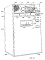
- the vending machine 200 is mounted in an enclosure cabinet having a back wall 201, spaced side walls 202 and 204, a front panel 205, a top wall 206 and a bottom wall 208.
- the front panel 205 is preferably hingedly secured to side wall 202 and provided with a key actuated lock 210 securing the front panel 205 in a closed and locked position to prevent unauthorized access to the interior of the enclosure.
- a currency receiving mechanism 212 adapted to accept both coins and bills is mounted on front panel 205 along with a coin return slot 214 for returning change to the customer.
- Selector plates 216, 218, 220 and 222 are mounted on the front panel 205 for use by the customer to designate the food item selected to be heated and dispensed through a delivery passage 224 closed by a protective door 225.
- Product identification panels 215, 217, 219 and 221 are associated with selector plates 216, 218, 220 and 222, respectively, to inform the customer what food item can be selected by touching one of the selector plates.
- Identification panel 215 is provided with a graphic illustration of fried potatoes permitting use of the vending machine 200 by persons who do not speak or read a particular language. Additional indicia including words, numerals or other and graphic representations may be applied to each of the panels 215, 217, 219 and 221.
- a condiment holding chamber 209 is provided for holding packets of salt, pepper, sugar, ketchup, mustard and barbecue sauce.
- a refrigerated food storage cabinet 170 is preferably mounted in the lower portion of the interior of the enclosure 200 and package handling apparatus 40 and oven 70 are mounted above and adapted to receive selected packages of food products from the refrigerated storage compartment 170 transported by an elevator 180.
- Each selector plate 216, 218, 220 and 227 is preferably connected to an electrical circuit adapted to initiate a sequence of events provided that payment for the food item 30 has been received in the currency receiving mechanism 212.
- touching selector plate 220 indicates that pizza, graphically illustrated on product identification panel 219 is to be dispensed.
- a container 10 containing pizza will be automatically moved from the refrigerated storage compartment 170 onto an elevator 180 and delivered to the package handling apparatus 40 which will move the package 10 to oven 70 for heating and then dispense the heated product 30 through the delivery passage 224 which is accessible to the customer by raising door 225.
- the electrical circuit controlling the heating of the selected food product 30 preferably includes three programmed elements for delivering a predetermined type of heating for a pre-programmed time interval to the selected food product.
- the programmable circuit preferably includes, for example, devices to program the heating cycle by coordination with the location of the selected food item in the storage compartment 170, a bar code or other readable mechanism on the package, and symbols displayed on or adjacent selector plates 215-221 for the user to touch. From the foregoing, it should be readily apparent that touching one of the selector plates 216, 218, 220 or 222 based on the visual selection of a food item graphically illustrated on product identification panels 215, 217, 219 or 221 initiates a programmed sequence to control the heating cycle of the selected food product 30.
- Package 10 comprises a tubular sleeve 12 having open ends 13a and 13b.
- Sleeve 12 is formed by a top 14, bottom 15 and side walls 16a and 16b having peripheral edges connected to form an interior cavity 17 for a container 18.
- Bottom 15 is narrower than top 14 and sidewalls 16a and 16b are inclined relative to vertical planes.
- Container 18 is an open topped tray formed by side walls 20 and 21 having end walls 22 and 23 secured between opposite ends thereof and a bottom wall 24.
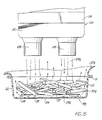
- Support ribs 25 or other suitable projections extend upwardly from bottom wall 24 for supporting a food product 30 spaced from bottom wall 24 to provide space forming a path 28 extending between the lower surface 31 of the food product 30 and the upper surface 25a of the bottom wall 24 of container 18.
- the package 10 carries the food product 30 in the open-top container 18 which is enclosed in the tube-like sleeve 12, preferably constructed of cellulosic or other poorly conductive material.
- the food product 30 is stored in a cabinet 170 in the container 18 inside of the sleeve covers 12.
- the container 18 is withdrawn from the sleeve 12 prior to heating the food product 30 and then the food 30 and container 18 are returned to the sleeve 12 to retain heat in the food until the package 10 is opened by the customer.
- Cabinet 170 may be refrigerated or divided into compartments, some of which are refrigerated depending upon the nature of the food product to be dispensed by the vending machine 200.
- the relatively non-conducting sleeve 12 serves as a comfortable holder for the hot container 18 and food 30.
- the numeral 18a generally designates a modified form of the container having a susceptor belt 27 mounted adjacent bottom 24 of the container having ribs 25 formed thereon.
- the susceptor belt coating 27 is formed of polyethylene terephthalate and is commercially available from a variety of sources including Frigigold of England and is recommended for use in reusable plastic or paperboard microwave cook ware in a recommended temperature range of up to 232°C (450°F).
- the susceptor belt 27 is rapidly heated by microwave energy until it reaches a maximum temperature of, for example, 177°C (350°F) and the temperature level is maintained to provide radiant and conductive bottom heat to the food product 30.
- a layer 29 of a particulate food product such as strips of pasta or slices of potato, is positioned between the bottom wall 24 of container 18 and the lower surface 31 of food product 30.
- layer 29 is slices of potato and product 30 is a meat product
- juices dripping from the lower surface of food product 30 will contact and be absorbed by layer 29 of potato slices to enhance the cooking of both the slices of potato and the meat product 30.
- the liquid juices enhance the flavor and appearance of the potatoes while the circulation of air through passages 28 between the potato slices results in controlled drying and evaporation of moisture from the bottom of the food product 30 to provide an acceptable texture, taste, smell and appearance superior to that conventionally achieved in microwave ovens.
- the food product 30a may comprise particulate material, such as slices of fried potatoes and a corrugated susceptor belt 27 is mounted adjacent bottom 24 to form ribs 25. Since the susceptor belt 27 is controllably heated by the microwave and portions of the upwardly extending ribs 25 contact the lower surface of the food product, the structure simulates grilling as well as allowing juices to flow into the area between the ribs.
- Container 18b illustrated in FIG. 15, is provided with a sheet 27a of a heat shrinkable film bonded to lip 19a for sealing the food product 30a in the container 30b.
- a sheet 27a preferably formed of polymeric compounds and materials, for example, synthetic thermoplastic resins of the type which are commercially available from E.I. DuPont de Nemours and Co. of Wilmington, Delaware, used to form a polyester film which will melt when contacted by air at a temperature of less than 204°C (400°F) which results in film 27a becoming perforated and rolling toward lip 19 which extends around the periphery of container 18b.
- the cohesive nature of the polyester material prevents it from dripping into the food container. It should be readily apparent that the use of the polyester film 27a provides a seal which prevents deterioration of food product 30a over an extended period of time in a refrigerator or freezer.
- a perforated grid or lattice 27b may be mounted between the upper surface of lip 19 and the lower surface of sheet 27a.
- Legs 27c and 27d spanning across the top of container 18b support film 27a to assure that portions of film 27a do not drop downwardly to engage the food product 30a in container 18b.
- film 27a and lattice 27b are bonded or otherwise sealingly secured to the lip 19 which extends around the periphery of the open top of container 18b to prevent dehydration and to otherwise protect food product 30 in container 18b.
- Food product 30 is supported on susceptor belt 27 having upwardly extending projections 25 formed thereon for spacing the lower surface of food product 30 above the bottom of container 18b to form air passages therebetween as hereinbefore described.
- impingement of air stream 28a against the upper surface of film 27a causes a central portion of film 27a to be perforated forming an opening 27a' in a central portion of the film intermediate edges of container 18b.
- opening 27a' is enlarged as heat is transferred to the film 27a which tends to roll back as indicated at 27a" as the film material shrinks and is distorted.
- heat transferred to the film 27a causes the meltable and shrinkable film 27a to retract to the position designated 27a''' thereby uncovering the upper surface of food product 30 in container 18b.
- container 18b is preferably stored in a tubular sleeve 12 of the type hereinbefore described to prevent perforation of sealing film 27a during handling of containers while being transported for stocking storage cabinet 170.
- container 18b is reinserted into the tubular sleeve 12 prior to dispensing the food product to the customer so that the hot container 18b and the food product 30 therein can be handled by the customer to eliminate the necessity for providing "hot pads" or other apparatus for handling the hot container.
- package handling apparatus 40 includes a container loading device 50 and a container unloading device 60.
- the loading device 50 and unloading device 60 are of substantially identical construction and comprise motors 51a and 51b, respectively, drivingly connected through synchronous drive belts 52 to the end of drive screws 56.
- Each drive screw 56 has threads formed on the outer surface thereof which engage internal threads in a drive nut 55 which moves linearly along drive screw 56 as the drive screw rotates. Thrust is transmitted from the drive nut 55 to a transitional tube 57.
- the entire screw 56 and nut 55 assembly is protected from contamination and environmental elements by a cover tube 58, and an end wiper seal 59.
- Rotational thrust bearings 54 allow the screw 56 to freely rotate under loaded conditions.
- the electromechanical linear actuators 50 and 60 are commercially available from Jasta, Inc. of San Jose, California and from Dayton Electric Manufacturing Co. of Chicago, Illinois, and form no part of the invention except in the claimed combination.
- Motors 51a and 51b are preferably variable speed reversible synchronous gear motors. It should be readily apparent that motors 51a and 51b transmit torque through belt 52 for rotating drive screws 56. Rotation of drive screw 56 causes drive nut 55 which is secured to the inner end of translating tube 57 to move translating tube 57 to extend or retract tube 57 relative to cover tube 58.
- electromechanical actuator 60 having rake plate 57b mounted thereon is pivotally mounted between a pair of lugs 60a and is rocked in a vertical plane by a solenoid 60b connected to an actuating arm 60c secured to cover tube 58 of actuator 60.
- rake plate 57b When rake plate 57b is in its retracted home position indicated in dashed outline at 57b in FIG. 5 of the drawing, rake plate 57b is preferably positioned at an elevation above container 18 such that when translating tube 57 is extended to the full outline position, the lower edge of rake plate 57b moves above the upper edge of container 18.
- solenoid 60b is actuated for moving rake plate 57b downwardly to an elevation below the lip extending around container 18 such that when translating tube 57 is retracted to the dashed outline position, container 18 will be returned through passage 48 in product guide member 46 and returned to the interior of tubular sleeve 12.
- solenoid 60b will again be actuated for elevating rake plate 57b to a position above the upper edge of opening 48 such that pusher plate 57a may be actuated for moving the next container 18 into the oven.
- Conveyor 65 includes a flexible belt 66 extending around a drive roller 66a and a driven roller 66b, drive roller 66a being driven by a reversible variable speed motor 68.
- the in-feed conveyor generally designated by the numeral 42, comprises a paddle 43 suspended between chains 43a and 43b which extend around drive sprockets mounted on a shaft driven by a motor 43d.
- the infeed conveyor 42 is mounted between guide members 44 and 46.
- guide member 44 comprises a generally L-shaped member formed by substantially perpendicularly disposed legs 44a and 44b connected by a transition section 44c.
- Product guide member 44 is connected to a second product guide member 46 by a front bracket 42f and a rear bracket 42r.
- an in-feed drive motor 43d is secured to guide member 46 and paddle 43 is moved between guide members 44 and 46 by chains 43a and 43b.
- Product guide member 46 is formed by generally perpendicularly disposed legs 46a and 46b connected by a transition section 46c.
- a third leg 46d extends generally parallel to leg 46b and has an end secured to an end of leg 46b by stop member 45.
- stop member 45 functions as a stop to limit movement of package 10.
- Leg 46b of product guide member 46 has a first passage 47 formed therein while section 44d has a second passage 48 formed therein.
- the open end 13a of tubular sleeve 12 is positioned adjacent opening 47 while the open end 13b of sleeve 20 is positioned adjacent passage 48.
- motor 51a of the linear actuator of loader assembly 50 is energized, tube 57 and push plate 57a on the end thereof will move through passage 47 and through the open end 13b of sleeve 12 for moving container 18 through the open end 13a of sleeve 12 and through passage 48 into a cooking chamber in oven 70.
- motor 51a is reversed, thereby retracting translating tube 57 and push plate 57a to the position illustrated in FIG. 1 of the drawing.
- motor 51b of the linear actuator of the unloading assembly 60 will be energized to extend the translating tube 57 of the unloading assembly 60 causing the rake plate 57b to move into the cooking compartment above container 18 and then pivot downwardly for engaging lip 19 on end wall 21 on container 18.
- Motor 51b is then reversed for retracting tube 57 and rake plate 57b for urging container 18 out of the oven 70, through passage 48 and through the open end 13a of sleeve 12.
- motor 68 is energized, the heated food product 30 in container 18 which has been repositioned in sleeve 12 will be moved toward the delivery end of conveyor 65.
- Product guide members 44 and 46 are bolted or otherwise secured to the upper surface of loader base member 42a upon which in-feed conveyor 42 and delivery conveyor 65 are mounted.
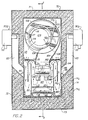
- the oven 70 comprises spaced side walls 72 and 74, a back wall 76 and a front wall 78.
- Front wall 78 has an access opening 79 formed therein which is opened or closed by a door 80.
- a microwave trap 81 is formed around door 80 and is configured to prevent passage of microwave energy through space between the periphery of the door 80 and walls of the oven 70.
- Top wall 71 and bottom wall 73 close upper and lower ends of oven 70.
- Each wall of the oven is preferably formed by spaced metallic sheets and the space between the sheets is filled with thermal insulation material.
- Actuator 82 secured to mounting bracket 82a, is connected through a link 84 to door 80 for moving door 80 vertically relative to access opening 79.
- Actuator 82 is preferably an electromechanical actuator of the type illustrated in FIG. 14 and is driven by a motor 51a.
- electromagnetic radiation device 90 in the illustrated embodiment comprise a pair of magnetrons 92 connected to wave guides 93 formed in side walls 72 and 74 of oven 70.
- the magnetrons 92 supply electromagnetic energy to wave guides which carry the energy to the cooking chamber.
- a preferred microwave frequency is 2450 megahertz.
- Magnetrons 92 are conventional vacuum tubes in the microwave oven that convert electrical energy to electro magnetic energy in the microwave frequency spectrum. Waves of microwave energy are similar to radio waves except they are higher frequency than radio waves lower frequency than ordinary light waves.
- the microwave energy is channeled through wave guides 93 from the magnetrons 92 into the cooking chamber 120.
- the side walls 72 and 74 are formed by spaced sheets 74a and 74b and insulation material 74c is configured to form a guide tube 93 having a lower end 94 which is inclined at an angle 95 relative to a vertical plane 96 at an angle in a range between 15° and 75°.
- the angle 95 is approximately 45°.
- microwave radiant heating is delivered from two sides and angles downwardly toward food 30 in an open top container 18. Since the container and the food in the container do not reflect microwave significantly and since the space under the container diffuses microwave which passes through or by the container the beam from one wave guide is not reflected directly into the other but is largely retained in the heating chamber.
- the container 18 is non-metallic reflections from one wave guide 93 are not reflected into the other to keep microwave in the chamber 120 to effectively heat the food 30.
- the container preferably is formed of material which is less than 25% reflective of microwave energy, such material being heated by the microwave to heat the surface of the food product where it contacts the surface of the container.
- the support for the open package is preferably less than 25% reflective of the microwave.
- the reflective surface of the bottom 24 of the container 18 is greater than one-fourth wave length, for 2450 megahertz (MHZ) microwave one-fourth of 13 cm, below the surface of food being heating.
- MHZ megahertz
- a tube 103 is connected through a valve 103a to a supply of water or steam and which may be used for delivering an atomized spray of water or steam into the air conditioning chamber 115 for controlling the relative humidity and dew point of air circulated through air conditioning chamber 115 and cooking chamber 120.
- air circulating apparatus generally designated by the numeral 100 comprises a blower housing 102 having an inlet opening 104 and a discharge opening 106.
- blower housing 102 is in the form of a volute and a plenum section 108 is formed adjacent the discharge opening 106.
- a radial flow fan impeller 110 draws air axially through inlet opening 104 and discharges air radially through plenum section 108 and discharge opening 106.
- a heating element 112 having coils 113 of a first stage and coils 114 of a second stage is mounted for heating air drawn into the blower housing 102.
- Perforated plate 75 is constructed of a metallic material and has perforations 76 with relatively small openings equivalent to more than 50% of the surface area.
- the perforated metal sheet 75 prevents microwave energy from passing into the air conditioning chamber 115.
- the first stage of coils 113 is mounted in air conditioning chamber 115 outside of the blower housing 102 while the second stage 114 of coils is mounted inside blower housing 102.
- Terminals 112a and 112b of heating element 112 are connectable to a suitable source of electricity.
- a mounting plate 116 having a notch 117 formed in the periphery thereof and a central opening 118 is bolted or otherwise secured to blower housing 102 for supporting heating element 112.
- Plate 116 is formed in two parts which are connectable along a part line 119.
- blower 110 is mounted on a shaft which is driven through a coupling 111 by a motor 110a.
- Coils 109 of a third stage heating element 109 is mounted in the plenum section 108 of blower housing 102 and positioned such that air delivered radially from blower 110 is heated immediately prior to being delivered through discharge opening 106. It should be readily apparent that only coils 109 may be activated while coils 113 and 114 are idle, if it is deemed expedient to do so depending upon the heating requirements of a particular food product.
- An air dispensing duct generally designated by the numeral 125 is secured to plenum 108 for receiving air from discharge opening 106.
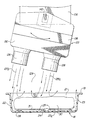
- air dispensing apparatus 125 comprises a tapered duct formed by a perforated plate 126 having an array of passages formed therein which communicate with tubes 128.
- a front wall 130 and a rear wall 132 extend upwardly from the perforated plate 126 and are connected between side walls 134 and 136.
- An inclined top wall 138 extends between front wall 130 and a flange 140 encircling the lower end of plenum 108 and enclosing the discharge opening 106 from the blower housing 102.
- air directing vanes 143 extend between side walls 134 and 136 of the tapered duct for distributing air along the length of the interior of the tapered duct.
- the air dispensing apparatus 125 is pivotally secured to duct 108 by a pivot pin 142 extending through aligned apertures 144 in flange 140. Pivot pin 142 extends into an opening 145 formed in lug 146 on shaft 148 which extends into an aperture 149 on a link 150. Link 150 has an elongated slot 152 formed therein into which a pin 154 on crank 155 extends.
- Crank arm 155 has an aperture which receives a drive shaft 158 driven by motor 160 through a gear reducer 161.
- a radial blower 110 discharging its highest velocity air from the outer portion of the volute downwardly through shaped openings in tubes 128 to impinge upon a narrow food product 30 in the open top container 18.
- the air dispensing duct 125 is moved relative to the product 30 to give uniform coverage by the air streams.
- the sides 22 and 23 of the container 18 cause a portion of the air stream to be deflected to heat the sides and bottom 31 of product 30 in the container.
- the movement applies the air streams near one side of the container adjacent side wall 22 and then to the other side adjacent side wall 23 so that parts of the air streams are alternately applied to opposite exposed sides of the product 30 and are caused to alternate the lateral flow through loose stacks of food products 30 such as curled or random lengths of french fried potatoes.
- This alternating lateral air flow through paths 28 between support ribs 25 passes under and heats the lower side 31 of irregularly shaped products such as bone-in chicken parts.
- the moving air dispensing apparatus 125 provides moving reflective surfaces which serve as stirrers to help distribute the microwave energy in the cooking chamber 120.
- the spent air travels through space 129 between tubes 128, as illustrated in FIGS. 11 and 12 of the drawing.
- Spent air travels upwardly adjacent baffles 162 and is then directed downwardly by a curved surface 164 along a path between baffle 162 and baffle 166 downwardly toward soil collector pans 165.
- Soil collector pans 165 are preferably removably mounted and are maintained at a temperature which is less than the temperature of any other surface in the oven 70 for causing very fine smoke-type particles in the moving air to be collected on the coldest surface in the recirculating path. From soil pans 165 the recirculating air is directed upwardly between the outer surface of baffle 166 and sheet 74b of side wall 74 upwardly through passages formed in the perforated plate 75.
- Baffles 162 and 166 are preferably constructed of material which is relatively transparent to microwave energy. To assure that the soil collection pans 165 are maintained cooler than other surfaces in oven 70, the pans may be exposed to outside air or water cooling to facilitate collecting aerosol from the recirculating air.
- the disclosed method for controlling the temperature and surface texture of a food product which is to be delivered from vending machine 200 generally comprises delivery of a suitably packaged and preserved food product from a storage compartment 170 to an oven 70.
- the package 10 is positioned by back stop member 45 in a predetermined relationship relative to electromechanical linear actuators 50 and 60 and relative to access opening 79 communicating with cooking chamber 120 in oven 70.
- Actuation of the actuator of the loading device 50 results in movement of push plate 57a through tubular sleeve 12 for pushing container 18 out of sleeve 12 and into the cooking chamber 120.
- Streams 28a of air delivered through tubes 128 of the air circulating apparatus 100 melts and shrinks film 27a for uncovering food product 30 in the open top container 18.
- one or more air streams 128a after causing the food product 30a in container 18 to be uncovered will be delivered through the open top of container 18b. If the food product 30a in the container is strips or slices of pasta, potatoes or other particulate material, air from stream 128a will be delivered through the stacked material in heat transfer relation with the surface of the pieces of the food product.
- air dispensing duct 125 is preferably rocked causing air streams 128a and 128b to move across the surface of the food product between lateral edges thereof such that regions of controlled air pressure are alternately formed adjacent opposite sides of the product 30 such that temperature controlled air flows through passage 28 between the lower surface 31 of the food product and the upper surface 25a of the bottom 24 of container 18.
- the recirculating air tends to limit localized heating of the product by microwave energy delivered by magnetrons 92. Tips, and thin areas of the product which are rapidly heated by the microwave energy may actually dissipate heat to air in streams 128a and 128b to provide cooling to certain portions of the food product.
- air flow through the air circulating apparatus 100 is terminated, magnetrons 92 are turned off and blower actuator 82 is energized for moving the door upwardly to the position illustrated in FIG. 1 of the drawing.
- the electromechanical actuator of the container unloading device 60 is then actuated for moving rake plate 57b from the dashed outline position in FIG. 5 of the drawing to the full outline position. Rake plate 57b is then lowered and retracted for moving container 18 out of the oven and redepositing the hot container and the food therein in the tubular sleeve 12.
- conveyor 65 is energized for moving the heated food product toward the delivery passage 124 of the vending machine 200 such that the product is accessible to the customer by opening protective door 225.
Landscapes
- Physics & Mathematics (AREA)
- Electromagnetism (AREA)
- Engineering & Computer Science (AREA)
- Life Sciences & Earth Sciences (AREA)
- Food Science & Technology (AREA)
- General Physics & Mathematics (AREA)
- Mechanical Engineering (AREA)
- Thermal Sciences (AREA)
- Vending Machines For Individual Products (AREA)
- Constitution Of High-Frequency Heating (AREA)
- General Preparation And Processing Of Foods (AREA)
- Closing Of Containers (AREA)
Claims (36)
- Four à micro-ondes (70) permettant de commander la température et la texture de surface d'un produit alimentaire (30) comprenant: un meuble; des moyens de division perforés (75) dans ledit meuble divisant l'intérieur du meuble en une chambre de cuisson (120) et une chambre de conditionnement d'air (115); des moyens de circulation d'air (100) comprenant une hélice (110) située dans ladite chambre de conditionnement d'air pour aspirer l'air à travers lesdits moyens de division perforés et distribuer l'air de la chambre de conditionnement d'air (115) dans ladite chambre de cuisson; des moyens de chauffage dans ladite chambre de conditionnement d'air (115); et des moyens de chauffage par micro-ondes communiquant avec ladite chambre de cuisson, lesdits moyens de division perforés empêchant le transfert de l'énergie transférée par micro-ondes de ladite chambre de cuisson vers ladite chambre de conditionnement d'air (115), caractérisé en ce que les moyens de chauffage sont positionnés dans le flux d'air entre lesdits moyens de division perforés et ladite hélice.
- Four à micro-ondes selon la revendication 1, dans lequel les moyens communiquant avec lesdits moyens de circulation d'air (100) et ladite chambre de cuisson (120) comprennent des moyens de distribution (125).
- Four à micro-ondes selon la revendication 2, avec l'adjonction de moyens (142) assujettis de façon mobile auxdits moyens de distribution (125) dans ladite chambre de cuisson (120).
- Four à micro-ondes selon l'une quelconque des revendications 1 à 3, avec l'adjonction de moyens de manipulation de produit (50, 60) associés audit meuble, lesdits moyens de manipulation de produit étant adaptés pour introduire et extraire les produits (30) dans ledit et dudit meuble.
- Four à micro-ondes selon la revendication 4, lesdits moyens de manipulation de produit (50, 60) comprenant des moyens de poussée (50) adaptés pour introduire un produit (30) dans ledit meuble; et des moyens (60) faisant office de raclette adaptés pour extraire un produit (30) de ladite chambre de cuisson (120).
- Four à micro-ondes selon l'une quelconque des revendications 1 à 5, avec l'adjonction de moyens (103) communiquant avec lesdits moyens de circulation d'air (100) et ladite chambre de cuisson (120) adapté pour déposer de l'humidité à la surface d'un produit (30) dans la chambre de cuisson (120) quand la surface du produit est inférieure à une température prédéterminée et pour faire évaporer l'humidité de zones discrètes de la surface du produit quand la surface du produit dépasse ladite température prédéterminée.
- Four à micro-ondes selon l'une quelconque des revendications 1 à 6, comprenant de plus un récipient (18) ayant une paroi de fond (24) et des parois latérales (20, 21, 22, 23), des moyens de maintien (25) sur ladite paroi de fond (24) adaptés pour maintenir un produit alimentaire (30) espacé de ladite paroi de fond (24), et des moyens (18) pour diriger l'air pour qu'il se déplace entre la surface inférieure du produit alimentaire et le fond du récipient.
- Four à micro-ondes selon la revendication 7, ledit récipient (18) étant constitué d'un matériau qui réfléchit moins de 25% de l'énergie transportée par micro-ondes, un matériau de ce type étant chauffé par les micro-ondes afin de chauffer le fond du produit alimentaire (30) à l'endroit où il touche la surface du récipient (18).
- Four à micro-ondes selon la revendication 7 ou la revendication 8, ledit récipient (18) étant métallique et conducteur afin de transmettre la chaleur depuis les côtés du récipient vers la zone sous le produit (30) afin d'aider à chauffer le fond des produits.
- Four à micro-ondes selon l'une quelconque des revendications 7 à 9, comprenant de plus: des moyens (128) formant des orifices espacés adaptés pour délivrer une pluralité de courants d'air en direction dudit récipient (18); ledit four incluant de plus des moyens (142, 160) déplaçant lesdits moyens de distribution d'air par rapport audit récipient (18) de telle manière qu'au moins un desdits courants d'air soit dirigé vers ladite paroi latérale de telle manière que ce flux d'air soit induit à travers l'espace entre la surface inférieure du produit alimentaire et la paroi de fond du récipient.
- Four à micro-ondes selon la revendication 7, dans lequel lesdits moyens de chauffage par micro-ondes comprennent de plus des moyens de guidage d'ondes (94) inclinés d'un angle compris entre 15° et 75° par rapport à un plan s'étendant perpendiculairement à la paroi de fond (24) du récipient (18).
- Four à micro-ondes selon la revendication 11, ledit récipient (18) étant constitué d'un matériau qui réfléchit moins de 25% de l'énergie transportée par micro-ondes.
- Four à micro-ondes selon l'une quelconque des revendications 1 à 12, dans lequel lesdits moyens de circulation d'air (100) comprennent: un corps de soufflante (102) ayant des ouvertures d'admission (104) et d'échappement (106); et dans lequel ladite hélice qui est placée dans ledit corps de soufflante (102) est adaptée pour faire circuler l'air de l'ouverture d'admission (104) vers l'ouverture d'échappement (106);
le four à micro-ondes comprenant de plus: des moyens de retour d'air (162, 164) communiquant avec ladite ouverture d'admission (104); des moyens de récupération (165) dans lesdits moyens de retour d'air, et des moyens maintenant lesdits moyens de récupération (165) à une température inférieure à la température de circulation d'air afin de récupérer les particules en suspension dans l'air au voisinage desdits moyens de récupération (165). - Four à micro-ondes selon les revendications 2 et 13, dans lequel les moyens de distribution d'air (125) communiquent avec ladite ouverture d'échappement (106).
- Four à micro-ondes selon la revendication 14, dans lequel lesdits moyens de distribution d'air (125) comprennent un conduit formé par une plaque perforée (126) pourvu d'un réseau de passages (144) pour délivrer l'air depuis ladite chambre de conditionnement d'air (115) dans ladite chambre de cuisson (120); un réseau de tubes (128) assujetti à ladite plaque per-forée (126) permettant de recevoir l'air circulant au travers desdits passages; et des moyens (142) montant de manière pivotante ledit conduit dans ledit meuble pour un déplacement desdits tubes.
- Four à micro-ondes selon la revendication 15, avec l'adjonction d'une pluralité de pales dirigeant l'air (143) dans ledit conduit, lesdites pales étant élaborées pour diriger l'air au travers desdits passages et dans lesdits tubes (128).
- Four à micro-ondes selon la revendication 15 ou la revendication 16, ledit conduit étant constitué d'un matériau réfléchissant les micro-ondes qui agite l'énergie transportée par les micro-ondes dans la chambre de cuisson (120) lorsqu'il bouge.
- Four à micro-ondes selon l'une quelconque des revendications précédentes, dans lequel lesdits moyens de division perforés (75) comprennent une plaque constituée d'un matériau métallique ayant des perforations avec des ouvertures relativement petites équivalentes à plus de 50% de la zone de surface de la plaque, ladite plaque étant élaborée afin d'empêcher le passage de l'énergie transportée par micro-ondes de ladite chambre de cuisson (120) dans ladite chambre de conditionnement d'air (115).
- Four à micro-ondes selon l'une quelconque des revendications précédentes, lesdits moyens de chauffage comprenant un élément de chauffage électrique (112).
- Four à micro-ondes selon la revendication 1, lesdits moyens de circulation d'air dans ladite chambre de conditionnement d'air pour aspirer l'air au travers desdits moyens de division perforés et délivrer l'air de ladite chambre de conditionnement d'air dans ladite chambre de cuisson comprenant des moyens formant soufflante (100, 110) qui comprennent ladite hélice, lesdits moyens formant soufflante aspirant l'air de la chambre de cuisson à travers lesdits moyens de division perforés et distribuant l'air de ladite chambre de conditionnement dans ladite chambre de cuisson, lesdits moyens de division perforés (75) ayant de petites ouvertures élaborées pour empêcher le passage de l'énergie transportée par micro-ondes de ladite chambre de cuisson dans ladite chambre de conditionnement.
- Four à micro-ondes selon la revendication 20, lesdits moyens formant soufflante comprenant un corps de soufflante (102) dans ladite chambre de conditionnement d'air (115), ledit corps de soufflante (102) ayant un passage d'admission (104) et un passage de décharge (106).
- Four à micro-ondes selon la revendication 21, lesdits moyens de chauffage comprenant un étage de bobines (113) montées dans ladite chambre de conditionnement d'air à l'extérieur du corps de soufflante.
- Four à micro-ondes selon la revendication 21, comprenant de plus des moyens de distribution (125) montés dans ladite chambre de cuisson et communiquant avec ledit passage de décharge.
- Four à micro-ondes selon la revendication 23, avec l'adjonction de moyens (142) assujettissant de façon mobile lesdits moyens de distribution dans ladite chambre de cuisson.
- Four à micro-ondes selon la revendication 24, lesdits moyens de distribution (125) ayant des surfaces réfléchissant les micro-ondes qui servent de dispositifs d'agitation pour faciliter la distribution de l'énergie transportée par micro-ondes dans la chambre de cuisson.
- Four à micro-ondes selon la revendication 24, comprenant de plus: un plénum (108) communiquant avec ledit passage de décharge (106); un conduit communiquant avec ledit plénum; et des pales dirigeant l'air (143) dans ledit conduit permettant de distribuer d'air le long dudit conduit.
- Four à micro-ondes selon la revendication 26, ledit conduit comprenant des moyens formant des orifices espacés adaptés pour distribuer une pluralité de courants de flux d'air dans ladite chambre de cuisson; et des moyens déplaçant ledit conduit ce qui fait qu'au moins un desdits courants de flux d'air est directement induit au voisinage de la surface du produit alimentaire.
- Four à micro-ondes selon l'une quelconque des revendications 20 à 27, dans lequel lesdits moyens de chauffage par micro-ondes incluent des moyens de guidage d'ondes (93) inclinés d'un angle compris entre 15 degrés et 75 degrés par rapport à un plan s'étendant perpendiculairement auxdits moyens de division perforés (75).
- Four à micro-ondes selon la revendication 1, comprenant de plus un conduit de distribution d'air (125) dans ladite chambre de cuisson (120) au travers duquel l'air circule et est délivré dans ladite chambre de cuisson, ledit conduit de distribution d'air ayant des surfaces réfléchissant les micro-ondes; des moyens (142, 155, 160) permettant de déplacer ledit conduit de distribution d'air (125) ce qui fait que lesdites surfaces réfléchissant les micro-ondes sur celui-ci agitent l'énergie transportée par micro-ondes dans la chambre de cuisson.
- Four à micro-ondes selon l'une quelconque des revendications 1 à 19 comprenant de plus: un produit alimentaire (30) dans un récipient (10); un couvercle (12, 27a) sur ledit récipient (10); des moyens (50) pour découvrir ledit produit alimentaire (30) présent dans ledit récipient (10); et des moyens (12, 60) pour couvrir l'aliment et le récipient (10) chauffés après le chauffage.
- Four à micro-ondes selon la revendication 30, ledit récipient (10) comprenant une boíte à dessus ouvert (18) et ledit couvercle comprenant un fourreau (12) ayant un dessus (14) pour couvrir la boíte (18).
- Four à micro-ondes selon la revendication 30 ou la revendication 31, ledit couvercle comprenant un film fusible (27a) qui découvre l'aliment quand de l'air chaud projeté en direction du produit alimentaire est appliqué au film fusible.
- Four à micro-ondes selon l'une quelconque des revendications 30 à 32 dans lequel l'air est dirigé au niveau de la partie centrale de l'aliment présent dans le récipient à dessus ouvert (18) avec des côtés plus élevés que l'aliment, ledit air contactant la zone centrale de l'aliment puis se projetant en direction des côtés du récipient (18).
- Four à micro-ondes selon la revendication 33, selon lequel le produit alimentaire (30a) est un amas poreux de segments alimentaires en grande partie espacés comme des lanières de pâte ou des pommes de terre en lacets dans lequel l'air appliqué près du centre du récipient (18b) pénètre l'amas de produit afin de chauffer les couches inférieures de produit puis l'air circule vers les côtés du récipient pour s'échapper.
- Four à micro-ondes selon l'une quelconque des revendications précédentes, avec l'adjonction de moyens (216-222) associés auxdits moyens de chauffage (112, 113, 114) et auxdits moyens de chauffage par micro-ondes (90) afin de lancer un cycle de chauffage pré-programmé.
- Four à micro-ondes selon la revendication 35, dans lequel lesdits moyens (216-222) pour lancer un cycle de chauffage comprennent une pluralité de plaques de sélection (216-222) sur ledit meuble (72-78); et une pluralité de panneaux d'identification de produit (215-221) présentant des illustrations graphiques des différents produits alimentaires.
Priority Applications (2)
| Application Number | Priority Date | Filing Date | Title |
|---|---|---|---|
| EP00201074A EP1011297B1 (fr) | 1990-01-10 | 1991-01-09 | Machine de vente à chauffage par micro-ondes |
| EP00201073A EP1011082A3 (fr) | 1990-01-10 | 1991-01-09 | Machine de vente à chauffage par micro-ondes |
Applications Claiming Priority (2)
| Application Number | Priority Date | Filing Date | Title |
|---|---|---|---|
| US463279 | 1990-01-10 | ||
| US07/463,279 US5147994A (en) | 1990-01-10 | 1990-01-10 | Microwave vending machine |
Related Child Applications (2)
| Application Number | Title | Priority Date | Filing Date |
|---|---|---|---|
| EP00201074A Division EP1011297B1 (fr) | 1990-01-10 | 1991-01-09 | Machine de vente à chauffage par micro-ondes |
| EP00201073A Division EP1011082A3 (fr) | 1990-01-10 | 1991-01-09 | Machine de vente à chauffage par micro-ondes |
Publications (3)
| Publication Number | Publication Date |
|---|---|
| EP0437344A2 EP0437344A2 (fr) | 1991-07-17 |
| EP0437344A3 EP0437344A3 (en) | 1992-01-15 |
| EP0437344B1 true EP0437344B1 (fr) | 2001-03-21 |
Family
ID=23839555
Family Applications (3)
| Application Number | Title | Priority Date | Filing Date |
|---|---|---|---|
| EP91300136A Expired - Lifetime EP0437344B1 (fr) | 1990-01-10 | 1991-01-09 | Four à micro-ondes |
| EP00201073A Withdrawn EP1011082A3 (fr) | 1990-01-10 | 1991-01-09 | Machine de vente à chauffage par micro-ondes |
| EP00201074A Expired - Lifetime EP1011297B1 (fr) | 1990-01-10 | 1991-01-09 | Machine de vente à chauffage par micro-ondes |
Family Applications After (2)
| Application Number | Title | Priority Date | Filing Date |
|---|---|---|---|
| EP00201073A Withdrawn EP1011082A3 (fr) | 1990-01-10 | 1991-01-09 | Machine de vente à chauffage par micro-ondes |
| EP00201074A Expired - Lifetime EP1011297B1 (fr) | 1990-01-10 | 1991-01-09 | Machine de vente à chauffage par micro-ondes |
Country Status (9)
| Country | Link |
|---|---|
| US (4) | US5147994A (fr) |
| EP (3) | EP0437344B1 (fr) |
| JP (1) | JP3145719B2 (fr) |
| AT (2) | ATE199988T1 (fr) |
| AU (3) | AU651074B2 (fr) |
| CA (1) | CA2032588C (fr) |
| DE (2) | DE69132559T2 (fr) |
| ES (2) | ES2265863T3 (fr) |
| WO (1) | WO1993001019A1 (fr) |
Cited By (1)
| Publication number | Priority date | Publication date | Assignee | Title |
|---|---|---|---|---|
| US8071922B2 (en) | 2004-12-14 | 2011-12-06 | Enodis Corporation | Impingement/convection/microwave oven and method |
Families Citing this family (82)
| Publication number | Priority date | Publication date | Assignee | Title |
|---|---|---|---|---|
| US5818014A (en) * | 1990-01-10 | 1998-10-06 | Patentsmith Technology, Ltd. | Air dispensers for microwave oven |
| US5717192A (en) * | 1990-01-10 | 1998-02-10 | Patentsmith Technology, Ltd. | Jet impingement batch oven |
| US5401940A (en) * | 1990-01-10 | 1995-03-28 | Patentsmith Ii, Inc. | Oscillating air dispensers for microwave oven |
| US5147994A (en) * | 1990-01-10 | 1992-09-15 | Patentsmith Corporation | Microwave vending machine |
| US5254823A (en) * | 1991-09-17 | 1993-10-19 | Turbochef Inc. | Quick-cooking oven |
| US5434390A (en) * | 1991-09-17 | 1995-07-18 | Turbochef, Inc. | Quick-cookig oven |
| US5449888A (en) * | 1992-07-02 | 1995-09-12 | Patentsmith Technology, Ltd. | Microwave vending machine |
| US5799822A (en) * | 1994-04-21 | 1998-09-01 | Krh Thermal Systems | Vending machine including multiple failure control devices |
| US5503300A (en) * | 1994-04-21 | 1996-04-02 | Krh Thermal Systems | Vending machine including refrigeration and oven compartments |
| US5688423A (en) * | 1994-08-31 | 1997-11-18 | Krh Thermal Systems | Vending machine including multiple heat sources with programmable cook cycles |
| US5503061A (en) * | 1994-10-03 | 1996-04-02 | Krh Thermal Systems | Food cooking hot air dispensing apparatus |
| US5802959A (en) * | 1995-06-07 | 1998-09-08 | Heat And Control, Inc. | Baked, non-oil containing snack product food |
| US5997924A (en) * | 1997-02-04 | 1999-12-07 | Lmo Consultants, Inc. | Automated process for making pizza |
| US7092988B1 (en) | 1997-05-27 | 2006-08-15 | Jeffrey Bogatin | Rapid cooking oven with broadband communication capability to increase ease of use |
| US6464104B1 (en) | 1998-10-08 | 2002-10-15 | Gregory Waddell | Vending system |
| NL1010579C2 (nl) * | 1998-11-18 | 2000-05-23 | Prolion Bv | Werkwijze en inrichting voor het opwarmen van voedingsmiddelen. |
| AU770434B2 (en) * | 1999-05-25 | 2004-02-19 | Fritson Ag | Method and device for preparing foodstuffs by baking inside an oven cavity |
| GB2351490A (en) | 1999-07-01 | 2001-01-03 | Food Serv Tech Ltd | A demountable dispensing mechanism for a vending machine |
| GB9915335D0 (en) * | 1999-07-01 | 1999-09-01 | Food Serv Tech Ltd | Hot food vending machine |
| ATE289696T1 (de) * | 1999-11-25 | 2005-03-15 | Recreativos Presas S L | Verkaufsautomat für heisse sandwiches |
| US8224892B2 (en) | 2000-04-28 | 2012-07-17 | Turbochef Technologies, Inc. | Rapid cooking oven with broadband communication capability to increase ease of use |
| US6526961B1 (en) | 2000-07-10 | 2003-03-04 | Lincoln Foodservice Products, Inc | Conveyor oven |
| US6481433B1 (en) | 2000-11-17 | 2002-11-19 | Middleby Marshall Incorporated | Conveyor oven having an energy management system for a modulated gas flow |
| DE10116295A1 (de) * | 2001-03-31 | 2002-10-10 | Nexans France S A | Vorrichtung zur Stromübertragung zwischen zwei Endstellen |
| US6462319B1 (en) | 2001-05-29 | 2002-10-08 | Bsh Home Appliances Corporation | Multi-stage self-cleaning control for oven |
| US6592364B2 (en) | 2001-11-30 | 2003-07-15 | David Zapata | Apparatus, method and system for independently controlling airflow in a conveyor oven |
| US7530473B2 (en) * | 2002-02-26 | 2009-05-12 | Munroe Chirnomas | Thermal separating door in a vending machine |
| ITTO20020202A1 (it) * | 2002-03-08 | 2003-09-08 | Tortuga 3 Di Antoniazzi Barbar | Distributore automatico di pizze calde ed affini e relativo metodo difunzionamento. |
| US6751977B2 (en) * | 2002-04-17 | 2004-06-22 | Carrier Commercial Refrigeration, Inc. | Automated freezer component |
| US6808083B2 (en) | 2002-05-31 | 2004-10-26 | The Coca-Cola Company | Hot and cold vending apparatus |
| BRPI0309916B1 (pt) * | 2002-07-05 | 2018-06-12 | Turbochef Technologies, Inc. | Forno de cozimento em velocidade |
| US9351495B2 (en) * | 2002-07-05 | 2016-05-31 | Turbochef Technologies, Inc. | Air fryer |
| US8006685B2 (en) * | 2002-07-05 | 2011-08-30 | Turbochef Technologies, Inc. | Re-circulating oven with gas clean-up |
| US6777654B1 (en) | 2002-09-27 | 2004-08-17 | J.H.Trademark Company, Llc | Customer-engaging food merchandising module |
| WO2004076928A2 (fr) | 2003-02-21 | 2004-09-10 | Middleby Corporation | Four autonettoyant |
| US7266423B2 (en) * | 2003-02-27 | 2007-09-04 | David Odell Simmons | Facilitating vending of customer-configured pizza preparation kits |
| WO2004086317A2 (fr) * | 2003-03-24 | 2004-10-07 | Abudanza, Inc. | Distributeur automatique d'aliments chauds |
| WO2005002988A2 (fr) * | 2003-07-01 | 2005-01-13 | Walter Niemetz | Systeme et procede de stockage, de chauffage et d'emballage de produits alimentaires dans le lieu de consommation |
| US8035062B2 (en) * | 2003-07-07 | 2011-10-11 | Turbochef Technologies, Inc. | Combination speed cooking oven |
| WO2005044669A2 (fr) * | 2003-11-03 | 2005-05-19 | Steamway Franchise Sales, Inc. | Receptacle pour cuisson micro-ondes comprenant des compartiments separes pour cuisson croustillante et cuisson vapeur |
| KR101013376B1 (ko) † | 2003-12-10 | 2011-02-14 | 삼성전자주식회사 | 조리 장치 및 그 제어 방법 |
| US20070100495A1 (en) * | 2004-01-02 | 2007-05-03 | Simmons David O | Facilitating vending of customer-configured pizza preparation kits |
| US20070093933A1 (en) * | 2004-01-02 | 2007-04-26 | Simmons David O | Facilitating vending of customer-configured pizza preparation kits |
| US8087407B2 (en) | 2004-03-23 | 2012-01-03 | Middleby Corporation | Conveyor oven apparatus and method |
| US9585400B2 (en) | 2004-03-23 | 2017-03-07 | The Middleby Corporation | Conveyor oven apparatus and method |
| US20050261966A1 (en) * | 2004-05-19 | 2005-11-24 | Frank Ottomanelli | Automated food service system for remote recreational facilities |
| US7681409B2 (en) * | 2004-09-30 | 2010-03-23 | Hill Phoenix, Inc. | Curtain air admission assembly |
| EP1677578A1 (fr) * | 2004-12-30 | 2006-07-05 | Walter Niemetz | Installation pour le réchauffage de casse-croûtes en portions refrigerés ou congelés |
| USD559007S1 (en) | 2005-01-07 | 2008-01-08 | Kraft Foods Holdings, Inc. | Food kiosk |
| US8384000B2 (en) * | 2005-01-07 | 2013-02-26 | Kraft Foods Group Brands Llc | Apparatus for providing food service |
| US20060151488A1 (en) * | 2005-01-07 | 2006-07-13 | Kraft Foods Holdings, Inc. | Apparatus for providing food service |
| US8315733B2 (en) * | 2005-06-23 | 2012-11-20 | Hales Jr Walter | Apparatus and method for marketing products, distributing product samples and capturing consumer personal data |
| USD580678S1 (en) | 2005-07-12 | 2008-11-18 | Kraft Foods Global Brands Llc | Food merchandiser |
| US8455797B2 (en) * | 2007-05-15 | 2013-06-04 | Appliance Scientific, Inc. | High-speed cooking oven with optimized cooking efficiency |
| US7435931B1 (en) * | 2007-05-15 | 2008-10-14 | Appliance Scientific, Inc. | High-speed cooking oven with optimized cooking efficiency |
| US9006619B2 (en) * | 2007-10-09 | 2015-04-14 | Acp, Inc. | Cooking appliance including combination heating system |
| DE112008002708B4 (de) * | 2007-10-09 | 2017-09-28 | Acp, Inc. | Luftzirkulation für ein Gargerät mit einem Kombinations-Heizsystem |
| US8839714B2 (en) | 2009-08-28 | 2014-09-23 | The Middleby Corporation | Apparatus and method for controlling a conveyor oven |
| US9747253B2 (en) * | 2012-06-05 | 2017-08-29 | Redbox Automated Retail, Llc | System and method for simultaneous article retrieval and transaction validation |
| US9361745B2 (en) * | 2012-06-22 | 2016-06-07 | Lester Abston | Bagged ice vending machine |
| IN2013CH01041A (fr) * | 2013-03-12 | 2015-08-14 | Atchayam Business Solutions Pvt Ltd | |
| CN104346872B (zh) | 2013-08-05 | 2017-05-10 | 黄自升 | 一种食物自动烹制加工系统 |
| US9687110B2 (en) | 2013-12-04 | 2017-06-27 | Teca Technologies Limited | Pancake maker apparatus, methods and systems |
| WO2015154198A1 (fr) * | 2014-04-10 | 2015-10-15 | Walter Niemetz | Procédé et dispositif de chauffage d'aliments |
| US9560853B2 (en) * | 2014-12-23 | 2017-02-07 | Aleksandr Taslagyan | Return flow conveyor device for heating food items |
| DE102015225581A1 (de) * | 2015-12-17 | 2017-06-22 | Convotherm Elektrogeräte GmbH | Verfahren zum Betreiben eines gewerblichen Gargeräts |
| US10490014B2 (en) | 2016-12-16 | 2019-11-26 | Pepsico, Inc. | Lean vending machine |
| IT201700043109A1 (it) * | 2017-04-19 | 2018-10-19 | Martina Lisa Castellano | Apparecchiatura per la preparazione e distribuzione di prodotti alimentari da forno, in particolare pizze |
| TWI634520B (zh) * | 2017-07-18 | 2018-09-01 | 游本俊 | Cooking device for food vending machine |
| WO2019040112A1 (fr) * | 2017-08-21 | 2019-02-28 | Tigout Inc. | Machine de fabrication automatique de pâtisserie |
| US10543942B2 (en) | 2017-11-21 | 2020-01-28 | Fulfil Solutions, Inc. | Product handling and packaging system |
| PL233984B1 (pl) * | 2018-01-04 | 2019-12-31 | Food Robotics Spólka Z Ograniczona Odpowiedzialnoscia | Układ magazynowy automatu wydającego produkty żywnościowe |
| US20250117433A1 (en) * | 2018-02-02 | 2025-04-10 | Automated Retail Technologies, Llc | Automated side opening oven door for a vending machine |
| WO2019152606A1 (fr) * | 2018-02-02 | 2019-08-08 | Jukka Llc | Porte de four à ouverture latérale automatisée pour distributeur automatique |
| US12051308B2 (en) * | 2018-02-02 | 2024-07-30 | Automated Retail Technologies, Llc | Automated side opening door for a refrigerated enclosure of a vending machine |
| JP2020184283A (ja) * | 2019-04-27 | 2020-11-12 | 浩之 堀野 | 加熱食品自動販売機 |
| CN110176101B (zh) * | 2019-05-23 | 2024-01-16 | 湖南兴元科技股份有限公司 | 自动售货机及取货出货方法 |
| WO2021016326A1 (fr) * | 2019-07-23 | 2021-01-28 | Yo-Kai Express Inc. | Distributeur automatique d'aliments et procédé de distribution automatique d'aliments l'utilisant |
| WO2021154580A1 (fr) | 2020-01-28 | 2021-08-05 | Tigout Inc. | Appareil automatique de cuisson de produits de pâtisserie |
| CA3201335A1 (fr) | 2020-11-09 | 2022-05-12 | 24/7 Pizza Box, LLC | Distributeur automatique et systemes et procedes d'ouverture |
| TWI777341B (zh) * | 2020-12-29 | 2022-09-11 | 皇丞創新科技股份有限公司 | 自動加熱式販賣機 |
| CN116045591A (zh) * | 2023-03-06 | 2023-05-02 | 合肥华凌股份有限公司 | 升降机构及移动冰箱 |
Family Cites Families (42)
| Publication number | Priority date | Publication date | Assignee | Title |
|---|---|---|---|---|
| US3283113A (en) * | 1963-06-12 | 1966-11-01 | Lyons & Co Ltd J | Electronic oven for vending machine use |
| GB1119245A (en) * | 1965-07-13 | 1968-07-10 | Microtherm Ltd | Improvements in and relating to vending and dispensing mechanisms |
| US3343479A (en) * | 1965-09-08 | 1967-09-26 | Philips Corp | System for heating and vending packaged food |
| US3333666A (en) * | 1965-10-08 | 1967-08-01 | William R Murray | Electronic microwave cooking and vending machine |
| GB1170051A (en) * | 1966-01-10 | 1969-11-12 | Microtherm Ltd | Improvements in or relating to Article Dispensing Apparatus |
| US3404620A (en) * | 1966-08-22 | 1968-10-08 | Microtherm Ltd | Preparation of food products |
| US3386550A (en) * | 1966-11-15 | 1968-06-04 | William R. Murray | Automatic electronic microwave cooking and vending machine |
| US3442200A (en) * | 1967-02-21 | 1969-05-06 | Kurt Babel | Food vending apparatus |
| US3534676A (en) * | 1968-03-15 | 1970-10-20 | Robert A Rubino | Vending machine with fast cooking means |
| US3884213A (en) * | 1973-03-30 | 1975-05-20 | Donald P Smith | Cooking apparatus |
| US4004712A (en) * | 1975-10-21 | 1977-01-25 | Moyer Diebel Limited | Vending machine and microwave oven combination |
| US4081646A (en) * | 1976-03-15 | 1978-03-28 | Teckton, Inc. | Device for microwave cooking |
| US4154861A (en) * | 1976-05-19 | 1979-05-15 | Smith Donald P | Heat treatment of food products |
| US4492839A (en) * | 1976-05-19 | 1985-01-08 | Smith Donald P | Thermal treatment apparatus |
| US4289792A (en) * | 1976-05-19 | 1981-09-15 | Smith Donald P | Microwave treatment of food products |
| US4409453A (en) * | 1976-05-19 | 1983-10-11 | Smith Donald P | Combined microwave and impingement heating apparatus |
| US4190757A (en) * | 1976-10-08 | 1980-02-26 | The Pillsbury Company | Microwave heating package and method |
| US4144438A (en) * | 1977-09-28 | 1979-03-13 | The Procter & Gamble Company | Microwave energy moderating bag |
| US4398651A (en) * | 1978-08-17 | 1983-08-16 | Kumpfer Beverly D | Microwave food dispensing machine |
| US4431888A (en) * | 1978-12-21 | 1984-02-14 | Amana Refrigeration, Inc. | Microwave oven with improved feed structure |
| US4337116A (en) * | 1979-08-28 | 1982-06-29 | Keyes Fibre Company | Contoured molded pulp container with polyester liner |
| US4374318A (en) * | 1980-09-08 | 1983-02-15 | Umc Industries, Inc. | Apparatus for heating food, such as french fried potatoes |
| US4431889A (en) * | 1981-11-09 | 1984-02-14 | Raytheon Company | Combination microwave and convection oven |
| US4728762A (en) * | 1984-03-22 | 1988-03-01 | Howard Roth | Microwave heating apparatus and method |
| US4592485A (en) * | 1984-05-17 | 1986-06-03 | Meals Incorporated | Meal vending apparatus |
| JPH0126973Y2 (fr) * | 1984-10-05 | 1989-08-11 | ||
| SE459618B (sv) * | 1984-11-19 | 1989-07-17 | Bo Friberg | Varuautomat foer vaermning och utlaemning av faerdiglagade matportioner |
| US4626641A (en) * | 1984-12-04 | 1986-12-02 | James River Corporation | Fruit and meat pie microwave container and method |
| ES8700915A1 (es) * | 1985-02-09 | 1986-11-16 | Sankey Vending Ltd | Aparato para almacenar, calentar y despachar comidas |
| US4835351A (en) * | 1985-10-15 | 1989-05-30 | Donald P. Smith | Oven humidity reservoir |
| US4703148A (en) * | 1986-10-17 | 1987-10-27 | General Mills, Inc. | Package for frozen foods for microwave heating |
| JPS63180195A (ja) * | 1987-01-22 | 1988-07-25 | 株式会社 大都製作所 | 自動販売機用電子レンジ |
| US4745249A (en) * | 1987-02-19 | 1988-05-17 | Mrs. Paul's Kitchens Inc. | Package and method for microwave heating of a food product |
| US4825024A (en) * | 1987-06-01 | 1989-04-25 | General Mills, Inc. | Solid state ceramic microwave heating susceptor utilizing compositions with metal salt moderators |
| GB2217558B (en) * | 1988-04-11 | 1991-11-06 | Mb Group P L C | Vending systems for hot food |
| GB8808458D0 (en) * | 1988-04-11 | 1988-05-11 | Metal Box Plc | Food containers |
| US4925684A (en) * | 1988-08-19 | 1990-05-15 | Campbell Soup Company | Food package with a microwave releasable sealed closure |
| FR2637053B1 (fr) * | 1988-09-29 | 1990-11-16 | Scholtes Ets Eugen | Four de cuisson mixte |
| FR2638957B1 (fr) * | 1988-11-17 | 1994-07-08 | Corning France | Recipients combines pour la cuisson ou (et) la decongelation de produits alimentaires, notamment dans un four a micro-ondes |
| US5147994A (en) * | 1990-01-10 | 1992-09-15 | Patentsmith Corporation | Microwave vending machine |
| US5345069A (en) * | 1991-09-17 | 1994-09-06 | Oscar Mayer Foods Corporation | Microwavable frozen impact-resistant hermetically sealed food package |
| US5449888A (en) * | 1992-07-02 | 1995-09-12 | Patentsmith Technology, Ltd. | Microwave vending machine |
-
1990
- 1990-01-10 US US07/463,279 patent/US5147994A/en not_active Expired - Lifetime
- 1990-12-18 CA CA002032588A patent/CA2032588C/fr not_active Expired - Lifetime
-
1991
- 1991-01-04 AU AU68602/91A patent/AU651074B2/en not_active Ceased
- 1991-01-09 DE DE69132559T patent/DE69132559T2/de not_active Expired - Fee Related
- 1991-01-09 JP JP00120591A patent/JP3145719B2/ja not_active Expired - Fee Related
- 1991-01-09 DE DE69133536T patent/DE69133536T2/de not_active Expired - Fee Related
- 1991-01-09 AT AT91300136T patent/ATE199988T1/de not_active IP Right Cessation
- 1991-01-09 EP EP91300136A patent/EP0437344B1/fr not_active Expired - Lifetime
- 1991-01-09 EP EP00201073A patent/EP1011082A3/fr not_active Withdrawn
- 1991-01-09 ES ES00201074T patent/ES2265863T3/es not_active Expired - Lifetime
- 1991-01-09 ES ES91300136T patent/ES2155054T3/es not_active Expired - Lifetime
- 1991-01-09 EP EP00201074A patent/EP1011297B1/fr not_active Expired - Lifetime
- 1991-01-09 AT AT00201074T patent/ATE331420T1/de not_active IP Right Cessation
- 1991-06-28 US US07/723,250 patent/US5210387A/en not_active Expired - Lifetime
- 1991-07-08 WO PCT/US1991/004801 patent/WO1993001019A1/fr not_active Ceased
-
1992
- 1992-07-02 US US07/909,077 patent/US5310978A/en not_active Expired - Lifetime
-
1994
- 1994-02-04 AU AU54890/94A patent/AU675259B2/en not_active Ceased
- 1994-07-15 AU AU67526/94A patent/AU682364B2/en not_active Ceased
-
1995
- 1995-07-12 US US08/501,304 patent/US5582758A/en not_active Expired - Lifetime
Cited By (1)
| Publication number | Priority date | Publication date | Assignee | Title |
|---|---|---|---|---|
| US8071922B2 (en) | 2004-12-14 | 2011-12-06 | Enodis Corporation | Impingement/convection/microwave oven and method |
Also Published As
| Publication number | Publication date |
|---|---|
| US5310978A (en) | 1994-05-10 |
| EP0437344A3 (en) | 1992-01-15 |
| DE69132559T2 (de) | 2001-07-05 |
| ES2265863T3 (es) | 2007-03-01 |
| EP1011297A3 (fr) | 2000-11-22 |
| CA2032588A1 (fr) | 1991-07-11 |
| US5147994A (en) | 1992-09-15 |
| EP1011082A3 (fr) | 2003-05-28 |
| EP0437344A2 (fr) | 1991-07-17 |
| AU6752694A (en) | 1994-10-06 |
| JPH04211895A (ja) | 1992-08-03 |
| CA2032588C (fr) | 2002-04-09 |
| EP1011297B1 (fr) | 2006-06-21 |
| DE69133536T2 (de) | 2007-06-21 |
| AU5489094A (en) | 1994-04-21 |
| AU651074B2 (en) | 1994-07-14 |
| EP1011297A2 (fr) | 2000-06-21 |
| ATE331420T1 (de) | 2006-07-15 |
| ES2155054T3 (es) | 2001-05-01 |
| DE69133536D1 (de) | 2006-08-03 |
| ATE199988T1 (de) | 2001-04-15 |
| US5210387A (en) | 1993-05-11 |
| AU682364B2 (en) | 1997-10-02 |
| AU675259B2 (en) | 1997-01-30 |
| WO1993001019A1 (fr) | 1993-01-21 |
| JP3145719B2 (ja) | 2001-03-12 |
| EP1011082A2 (fr) | 2000-06-21 |
| DE69132559D1 (de) | 2001-04-26 |
| AU6860291A (en) | 1991-07-18 |
| US5582758A (en) | 1996-12-10 |
Similar Documents
| Publication | Publication Date | Title |
|---|---|---|
| EP0437344B1 (fr) | Four à micro-ondes | |
| US5539187A (en) | Microwave oven for heating food products | |
| US5449888A (en) | Microwave vending machine | |
| CA2172714C (fr) | Four a cuisson rapide | |
| US4307286A (en) | Pulsating hot-air heat-up system | |
| KR100247864B1 (ko) | 음식물의 열처리 장치 및 방법 | |
| US4015085A (en) | Container for the microwave heating of frozen sandwiches | |
| EP1509889B1 (fr) | Distributeur automatique de produits chauds et froids | |
| CA2322319C (fr) | Distributrice d'aliments chauds a four micro-ondes integre | |
| KR100260584B1 (ko) | 마이크로웨이브 자판기 | |
| WO1991012597A1 (fr) | Distributeur automatique d'aliments chauds | |
| CA2013620C (fr) | Methode et appareil pour rechauffer ou cuire rapidement des produits alimentaires | |
| WO2010125465A1 (fr) | Module pour réchauffer un repas de restauration rapide accouplé à un équipement de vente automatique |
Legal Events
| Date | Code | Title | Description |
|---|---|---|---|
| PUAI | Public reference made under article 153(3) epc to a published international application that has entered the european phase |
Free format text: ORIGINAL CODE: 0009012 |
|
| AK | Designated contracting states |
Kind code of ref document: A2 Designated state(s): AT BE CH DE DK ES FR GB GR IT LI LU NL SE |
|
| PUAL | Search report despatched |
Free format text: ORIGINAL CODE: 0009013 |
|
| AK | Designated contracting states |
Kind code of ref document: A3 Designated state(s): AT BE CH DE DK ES FR GB GR IT LI LU NL SE |
|
| 17P | Request for examination filed |
Effective date: 19920619 |
|
| 17Q | First examination report despatched |
Effective date: 19941004 |
|
| GRAG | Despatch of communication of intention to grant |
Free format text: ORIGINAL CODE: EPIDOS AGRA |
|
| RTI1 | Title (correction) |
Free format text: MICROWAVE OVEN |
|
| GRAG | Despatch of communication of intention to grant |
Free format text: ORIGINAL CODE: EPIDOS AGRA |
|
| GRAH | Despatch of communication of intention to grant a patent |
Free format text: ORIGINAL CODE: EPIDOS IGRA |
|
| GRAH | Despatch of communication of intention to grant a patent |
Free format text: ORIGINAL CODE: EPIDOS IGRA |
|
| ITF | It: translation for a ep patent filed | ||
| GRAA | (expected) grant |
Free format text: ORIGINAL CODE: 0009210 |
|
| AK | Designated contracting states |
Kind code of ref document: B1 Designated state(s): AT BE CH DE DK ES FR GB GR IT LI LU NL SE |
|
| PG25 | Lapsed in a contracting state [announced via postgrant information from national office to epo] |
Ref country code: AT Free format text: LAPSE BECAUSE OF FAILURE TO SUBMIT A TRANSLATION OF THE DESCRIPTION OR TO PAY THE FEE WITHIN THE PRESCRIBED TIME-LIMIT Effective date: 20010321 |
|
| REF | Corresponds to: |
Ref document number: 199988 Country of ref document: AT Date of ref document: 20010415 Kind code of ref document: T |
|
| REG | Reference to a national code |
Ref country code: CH Ref legal event code: NV Representative=s name: FIAMMENGHI-FIAMMENGHI Ref country code: CH Ref legal event code: EP |
|
| REF | Corresponds to: |
Ref document number: 69132559 Country of ref document: DE Date of ref document: 20010426 |
|
| REG | Reference to a national code |
Ref country code: ES Ref legal event code: FG2A Ref document number: 2155054 Country of ref document: ES Kind code of ref document: T3 |
|
| ET | Fr: translation filed | ||
| PG25 | Lapsed in a contracting state [announced via postgrant information from national office to epo] |
Ref country code: DK Free format text: LAPSE BECAUSE OF FAILURE TO SUBMIT A TRANSLATION OF THE DESCRIPTION OR TO PAY THE FEE WITHIN THE PRESCRIBED TIME-LIMIT Effective date: 20010621 |
|
| PG25 | Lapsed in a contracting state [announced via postgrant information from national office to epo] |
Ref country code: GR Free format text: LAPSE BECAUSE OF FAILURE TO SUBMIT A TRANSLATION OF THE DESCRIPTION OR TO PAY THE FEE WITHIN THE PRESCRIBED TIME-LIMIT Effective date: 20010622 |
|
| REG | Reference to a national code |
Ref country code: GB Ref legal event code: IF02 |
|
| PG25 | Lapsed in a contracting state [announced via postgrant information from national office to epo] |
Ref country code: LU Free format text: LAPSE BECAUSE OF NON-PAYMENT OF DUE FEES Effective date: 20020109 |
|
| PLBE | No opposition filed within time limit |
Free format text: ORIGINAL CODE: 0009261 |
|
| STAA | Information on the status of an ep patent application or granted ep patent |
Free format text: STATUS: NO OPPOSITION FILED WITHIN TIME LIMIT |
|
| 26N | No opposition filed | ||
| PGFP | Annual fee paid to national office [announced via postgrant information from national office to epo] |
Ref country code: ES Payment date: 20090218 Year of fee payment: 19 |
|
| PGFP | Annual fee paid to national office [announced via postgrant information from national office to epo] |
Ref country code: NL Payment date: 20090104 Year of fee payment: 19 Ref country code: DE Payment date: 20090102 Year of fee payment: 19 |
|
| PGFP | Annual fee paid to national office [announced via postgrant information from national office to epo] |
Ref country code: CH Payment date: 20090114 Year of fee payment: 19 |
|
| PGFP | Annual fee paid to national office [announced via postgrant information from national office to epo] |
Ref country code: BE Payment date: 20090213 Year of fee payment: 19 |
|
| PGFP | Annual fee paid to national office [announced via postgrant information from national office to epo] |
Ref country code: SE Payment date: 20090108 Year of fee payment: 19 Ref country code: IT Payment date: 20090127 Year of fee payment: 19 |
|
| PGFP | Annual fee paid to national office [announced via postgrant information from national office to epo] |
Ref country code: FR Payment date: 20090113 Year of fee payment: 19 |
|
| PGFP | Annual fee paid to national office [announced via postgrant information from national office to epo] |
Ref country code: GB Payment date: 20100120 Year of fee payment: 20 |
|
| BERE | Be: lapsed |
Owner name: *ENERSYST DEVELOPMENT CENTER INC. Effective date: 20100131 |
|
| REG | Reference to a national code |
Ref country code: NL Ref legal event code: V1 Effective date: 20100801 |
|
| REG | Reference to a national code |
Ref country code: CH Ref legal event code: PL |
|
| EUG | Se: european patent has lapsed | ||
| REG | Reference to a national code |
Ref country code: FR Ref legal event code: ST Effective date: 20100930 |
|
| PG25 | Lapsed in a contracting state [announced via postgrant information from national office to epo] |
Ref country code: CH Free format text: LAPSE BECAUSE OF NON-PAYMENT OF DUE FEES Effective date: 20100131 Ref country code: FR Free format text: LAPSE BECAUSE OF NON-PAYMENT OF DUE FEES Effective date: 20100201 Ref country code: LI Free format text: LAPSE BECAUSE OF NON-PAYMENT OF DUE FEES Effective date: 20100131 Ref country code: NL Free format text: LAPSE BECAUSE OF NON-PAYMENT OF DUE FEES Effective date: 20100801 |
|
| PG25 | Lapsed in a contracting state [announced via postgrant information from national office to epo] |
Ref country code: DE Free format text: LAPSE BECAUSE OF NON-PAYMENT OF DUE FEES Effective date: 20100803 |
|
| REG | Reference to a national code |
Ref country code: GB Ref legal event code: PE20 Expiry date: 20110108 |
|
| PG25 | Lapsed in a contracting state [announced via postgrant information from national office to epo] |
Ref country code: BE Free format text: LAPSE BECAUSE OF NON-PAYMENT OF DUE FEES Effective date: 20100131 |
|
| PG25 | Lapsed in a contracting state [announced via postgrant information from national office to epo] |
Ref country code: IT Free format text: LAPSE BECAUSE OF NON-PAYMENT OF DUE FEES Effective date: 20100109 |
|
| REG | Reference to a national code |
Ref country code: ES Ref legal event code: FD2A Effective date: 20110407 |
|
| PG25 | Lapsed in a contracting state [announced via postgrant information from national office to epo] |
Ref country code: ES Free format text: LAPSE BECAUSE OF NON-PAYMENT OF DUE FEES Effective date: 20110324 Ref country code: GB Free format text: LAPSE BECAUSE OF EXPIRATION OF PROTECTION Effective date: 20110108 |
|
| PG25 | Lapsed in a contracting state [announced via postgrant information from national office to epo] |
Ref country code: ES Free format text: LAPSE BECAUSE OF NON-PAYMENT OF DUE FEES Effective date: 20100110 |
|
| PG25 | Lapsed in a contracting state [announced via postgrant information from national office to epo] |
Ref country code: SE Free format text: LAPSE BECAUSE OF NON-PAYMENT OF DUE FEES Effective date: 20100110 |