EP0437612B1 - Enregistreur - Google Patents
Enregistreur Download PDFInfo
- Publication number
- EP0437612B1 EP0437612B1 EP90904672A EP90904672A EP0437612B1 EP 0437612 B1 EP0437612 B1 EP 0437612B1 EP 90904672 A EP90904672 A EP 90904672A EP 90904672 A EP90904672 A EP 90904672A EP 0437612 B1 EP0437612 B1 EP 0437612B1
- Authority
- EP
- European Patent Office
- Prior art keywords
- ink
- recording
- thin plate
- holes
- voltage
- Prior art date
- Legal status (The legal status is an assumption and is not a legal conclusion. Google has not performed a legal analysis and makes no representation as to the accuracy of the status listed.)
- Expired - Lifetime
Links
Images


Classifications
-
- B—PERFORMING OPERATIONS; TRANSPORTING
- B41—PRINTING; LINING MACHINES; TYPEWRITERS; STAMPS
- B41J—TYPEWRITERS; SELECTIVE PRINTING MECHANISMS, i.e. MECHANISMS PRINTING OTHERWISE THAN FROM A FORME; CORRECTION OF TYPOGRAPHICAL ERRORS
- B41J2/00—Typewriters or selective printing mechanisms characterised by the printing or marking process for which they are designed
- B41J2/005—Typewriters or selective printing mechanisms characterised by the printing or marking process for which they are designed characterised by bringing liquid or particles selectively into contact with a printing material
-
- Y—GENERAL TAGGING OF NEW TECHNOLOGICAL DEVELOPMENTS; GENERAL TAGGING OF CROSS-SECTIONAL TECHNOLOGIES SPANNING OVER SEVERAL SECTIONS OF THE IPC; TECHNICAL SUBJECTS COVERED BY FORMER USPC CROSS-REFERENCE ART COLLECTIONS [XRACs] AND DIGESTS
- Y10—TECHNICAL SUBJECTS COVERED BY FORMER USPC
- Y10S—TECHNICAL SUBJECTS COVERED BY FORMER USPC CROSS-REFERENCE ART COLLECTIONS [XRACs] AND DIGESTS
- Y10S101/00—Printing
- Y10S101/37—Printing employing electrostatic force
Definitions
- the present invention relates to a recording apparatus which realizes recording by electrostatically absorbing ink from a member impregnated with the ink and the adhereing the ink on a recording medium.
- US-A-3 834 301 discloses a recording apparatus comprising: a thin plate member providing holes, an ink reserving member which is provided close to one side of the thin plate member and is impregnated with conductive ink, and an electrode member, arranged on the other side of the thin plate member so as to permit the interposition of a recording medium between the electrode member and said other side of the thin plate member, for applying an electrostatic force to attract the conductive ink on said one side of the thin plate member through said holes.
- a recording apparatus comprising: a thin plate member providing holes, an ink reserving member which is provided close to one side of the thin plate member and is impregnated with conductive ink, an electrode member, arranged on the other side of the thin plate member so as to permit the interposition of a recording medium between the electrode member and said other side of the thin plate member, for applying an electrostatic force to attract the conductive ink on said one side of the thin plate member through said holes, characterised in that the thin plate member has holes which are not filled with ink, and the ink reserving member and the electrode member are arranged facing each other with the gap therebetween taken up by the thin plate member and the recording medium.
- Figure 1 is a diagram for explaining the recording principle of a recording apparatus of the present invention.
- a structure provides an electrode 1, a recording medium 100, a thin plate member (mesh) 2 boring a through hole 3 in the thickness direction thereof and an ink (layer) 8.
- the thin plate member 2 is kept dry from the ink 8 (contact angle 0 ⁇ 90°), the ink 8 cannot enter the hole 3 if pressure is not applied (such pressure can be adjusted depending on the surface tension).
- a wet angle 0 between the hole 3 like a pipe in the radius r and the ink 8 is considered as 90° and the surface tension of ink as ⁇ .
- the surface tension affectuates in the direction of interfering inflow of ink as the force (pressure) p expressed as follow.
- p 2 ⁇ r ⁇ / ⁇ r2 (dyne/cm2) (1)
- ⁇ 60 dyne/cm
- the pressure p becomes equal to 1.7 x 10⁴ (dyne/cm2) and when the pressure higher than p is applied, the ink enters the hole.
- an electrostatic force f is considered.
- thickness of recording medium 100 is assumed as d1
- dielectric constant thereof as ⁇ 1
- thickness of hole 3 (air layer) d2
- dielectric constant thereof as ⁇ 2
- the electrostatic force f can be expressed as follow.
- d1 60 »m
- r1 specific dielectric constant of recording medium
- d2 50 »m
- r2 specific dielectric constant of air
- recording can be realized by applying a voltage higher than 1.67 kV.
- the recording may be done with a recording voltage lower than that of the prior art.
- such recording voltage can be lowered to 700 V or less.
- the present invention uses a thin plate member 2 providing the holes not filled with the ink and arranges closely both the ink reserving member 4 and electrode 1 in both sides of the thin plate member 2 and thereby remarkably lowers the recording voltage through use of thickness of thin plate member 2 as the gap.
- the adjacent electrodes does not ganerate leak and close layout can be realized and thereby high resolution can also be obtained.
- Fig. 1 is a diagram for explaining the principle of the present invention.
- Fig. 2 is a diagram for explaining a first embodiment.
- Fig. 3 is a diagram for explaining a second embodiment.
- Fig. 4 is a diagram for explaining a cleaning mechanism of the second embodiment.
- Fig. 5 is a diagram for explaining a third embodiment.
- Fig. 6 is a diagram for explaining a fourth embodiment.
- Fig. 7 is a diagram for explaining a fifth embodiment.
- Fig. 8 is a sectional view of the essential portion of the fifth embodiment.
- Fig. 9 is a diagram for explaining a sixth embodiment.
- Fig. 10 is a diagram for explaining a seventh embodiment.
- Fig. 11 is a diagram for explaining recording operations of the seventh embodiment.
- Fig. 12 is a diagram for explaining operations of the seventh embodiment.
- Fig. 13 is a diagram for explaining an eighth embodiment.
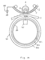
- Fig. 14 is a diagram for explaining a ninth embodiment.
- Fig. 15 is a diagram for explaining a tenth embodiment.
- Fig. 16 is a diagram for explaining operations of the tenth embodiment.
- Fig. 17 is a diagram for explaining an eleventh embodiment.
- Fig. 18 is a diagram for explaining operations of the eleventh embodiment.
- Fig. 2 is a diagram for explaining a first embodiment of a recording apparatus of the present invention.
- the numeral 1 designates many electrodes; 2, a metal mesh member providing many holes 3; 4, an ink roller as a member impregnated with the ink; 5, a power supply (voltage applying means).
- the electrodes 1 are are formed by burying metal members in a line with the pitch of 140 »m at the surface of a platen 6 along the axial direction of the ink supply roller 4.
- a voltage of the power supply 5 is applied to the metal members 1a, 1b, across well known driver circuits (not illustrated) formed to apply a voltage individually so that it can be selectively operated in accordance with a recording signal (video signal) sent from the host apparatuses.
- the mesh member 2 is formed, for example, by boring circular holes in diameter of 100 »m with a pitch of 140 »m to a stainless steel plate of thickness of 60 »m and is arranged on the electrodes 1 through a recording sheet 7.
- the electrodes 1 are aligned with the holes 3 and as will be exlained later, the ink is adhered on the recording sheet 7 at the position corresponding to the electrode to which a voltage is applied, thereby realizing the recording operation.
- the ink roller 4 is formed by fitting a member to impregnate the water conductive ink 8 to the external circumference of the conductive shaft member 4a.
- This member is, for example, formed by felt made of wool (JIS No. 3 (KF)) or sponge type member (Everlite HPN).
- This ink roller 4 is provided in contact with pressure to the mesh member 2 against the electrodes 1.
- the adequate ratio of surface tension is particularly important but it largely depends on thickness of mesh member 2 and diameter of hole 3 and must be adjusted within the range of 10 ⁇ 73 dyne/cm.
- the ink of 61.7 dyne/cm is used.
- the ink roller 4 is pressed to the mesh member 2 with a pressure of 10 ⁇ 100 g/cm2.
- the power supply 5 is connected with the electrodes 1 and mesh member 2 and the field is generated by applying a voltage across the ink 8 supplied into the hole 3 from the ink roller 4 and the electrodes 1.
- the voltage applied by the power supply 5 is related to thickness of the recording sheet 7.
- thickness of recording sheet 7 is not specially determined, the voltage must be increased as the recording sheet becomes thicker.
- a recording sheet 7 in the thickness of 65 um is used and voltage is set to 700V. Namely, a voltage can be lowered distinctively than the calculated value by pressing the ink roller 4 with the value explained above.
- a voltage supplied from the power supply 5 is selectively applied to the electrodes 1a, 1b, Vietnamese by the driving circuits not illustrated and the field is generated between the electrode and ink 8 by applying voltage across the selected electrode, for example, to the electrode 1a and ink 8.
- the ink 8 passes through the hole 3 provided opposed to the part of electrode 1a and adheres on the recording sheet 7 with the electrostatic force caused by the field.
- a command is given to the motor from MPU not illustrated to rotate the ink roller 4 in the clockwise direction indicated by the arrow mark for the pedetermined quantity and also rotate the mesh member 2 and recording sheet 7 in the direction indicated by the arrow mark for the predetermined quantity.
- the ink reserving mesh member 2 is not filled with the ink and thereby the mesh member 2 and recording sheet 7 may be pressurized in contact with each other.
- distance between the ink roller 4 and electrodes 1 can be shortened up to the thickness of the mesh member 2 and the voltage to be applied can be lowered.
- the mesh member 2 operates as a gap holding mechanism, it is no longer necessary to arrange the ink roller 4, mesh member 2 and platen 6, etc. with high accuracy and thereby economical structure may be formed.
- the mesh member 2 is formed by the stainless steel, but other metal plate may also be used.
- the mesh member may also be formed by the materials other than the metal, for example, a polymer film providing many holes. In this case, a voltage is applied to the shaft member 4a of the ink roller 4 used as the electrode.
- the mesh member 2 can also employ a screen by weaving the stainless wire. This screen can be fabricated in the accuracy up to 500 mesh/inch and thereby high resolution recording can be realized.
- the stainless wire is woven in flat like a screen as the mesh member 2 in the accuracy of 400 mesh/inch (wire diameter is 18 »m and gap coefficient is 51 %).
- Such screen mesh member 2 has realized the recording of the dot in diameter of 50 »m on the recording sheet 100 under the recording condition as explained above.
- the nylon string can be fabricated in the accuracy up to 500 mesh/inch, while the tetlon string up to 460 mesh/inch.
- Fig. 3 is a diagram for explaining the second embodiment, while Fig. 4 is a diagram for explaining the cleaning mechanism thereof.
- the numeral 2 designates a mesh member. As explained for Fig. 2, countless number of holes 3 are provided thereto.
- the mesh member is formed as the endless member and is extended over the ink roller 4 and guide rollers 43, 44.
- the numeral 45 designates a switch which is provided corresponding to each electrode 1a, 1b, ... and is selectively turned ON and OFF in accordance with the video signal supplied from the host apparatus to apply a voltage across the metal shaft 4a of ink supply roller 4 and each electrode 1a, 1b,....
- the cleaning mechanism 42 provides a suction part 46 which comes close to the mesh member 2 when it has passed the recording part and a suction pipe 47 connected to this suction part 46 is also connected to a suction source not illustrated such as an air pump through a filter also not illustrated.
- the recording to the recording sheet 7 can be conducted in the same way as the first embodiment and the ink remaining in the hole 3 after the recording is sucked by the cleaning mechanism 42 and there by removed.
- the adhered ink is never left at the internal surface of hole 3 of mesh member 2 and the mesh member 2 can be used repeatedly.
- the guide rollers 43, 44 are rotated for a single or more turns under the condition that the suction source not illustrated is operated and the recording voltage is not applied to move the mesh member 2 for the cleaning purpose and then these guide rollers are stopped.
- Fig. 5 is a diagram for explaining the third embodiment.
- Numeral 50 designates a hollow cylindrical member filling the conductive ink 61 as explained in regard to other embodiments with both ends thereof closed.
- This hollow cylindrical member 50 is also provided with a slit 51 and an opening 52 along the center line thereof.
- an ink impregnating member 53 composed of felt made of wool or sponge is fitted to the slit 51, while a tube 54 to be connected to a large capacity ink tank is attached to the opening 52.
- This hollow cylindrical member 50 is stationary arranged and the endless mesh member 2 slidably moves among the external circumference of this hollow cylindrical member 50.
- the cleaning operation can be conducted by providing a cleaning mechanism 42.
- the recording opertion for a long period of time can be realized.
- Fig. 6 is a diagram for explaining a fourth embodiment.
- the elements like those in respective embodiments explained previously are designated by the like reference numerals.
- the reference numerals 62a, 62b designate recording sheet feed rollers to feed a recording sheet 7 formed like a cut sheet; 4, an ink roller comprising a sponge roller 59 composed of a sponge member impregnated with water conductive ink and a mesh member 63 which is wound around external circumference of sponge roller 59 with close contactness thereto and provides countless number of holes; 64, 65, bearings rotatably and removably supporting the conductive shaft member 4a of the ink roller 4; 66, a brush for grounding formed by earthed conductive brush or a conductive metal thin plate.
- the old ink roller 4 is replaced with a new ink roller 4 in which the sponge roller 59 is sufficiently impregnated with the ink and the holes of mesh member 63 are not clogged.
- Fig. 7 is a diagram for explaining the fifth embodiment and Fig. 8 is a sectional view of the essential portion thereof.
- the elements like those in the respective embodiments explained above are designated by the like reference numerals.
- the numeral 4 designates an ink roller; 59, a sponge roller; 63, a mesh member; 67, a cartridge case accommodating therein the sponge roller 59 and ink roller 4 including mesh member 63 and providing the guiding projections 68a, 68b at the side surfaces thereof; 70, a recording apparatus body comprising a cassette loading part 70a to which a sheet cassette 71 holding cut sheets is loaded, a sheet transfer part 70b for carrying cut sheets, a recording part 70c for conducting recording on the cut sheets and a stacker part 70d to which recorded cut sheets are exhausted.
- the guide rails 72a, 72b are also provided for guiding the guiding projections 68a, 68b on the occasion of inserting or removing the cartridge case 67 along the axial direction of the ink roller 4.
- the loading part 70a is provided with a pick roller 73 for feeding cut sheets in the sheet cassette 71
- the sheet transfer part 70b is provided with the guide rollers 74a, 74b, 74c and guide plates 75a, 75b, 75c for carrying the cut sheets to the recording part 70c and stacker part 70d
- the recording part 70c is provided with a platen 6 on which the electrodes 1a, 1b, Vietnamese are arranged in the axial direction of ink roller 4 at the positions opposed to the ink roller 4.
- the platen 6 is formed so that it is set, by the lever member which is manually operated by an operator, to the position where the electrodes are pressurized in contact with the ink roller 4 by the presetn pressure and to the position where it is separated from the ink roller 4 when the processing is made for jamming condition of cut sheets and the cartridge case 67 is inserted or removed.
- the one end side of the cartridge case 67 is provided with a bearing 77 which rotatably holds the flange 76 disposed to the conductive shaft member 4a of ink roller 4 and a drive gear 79 which is engaged with the gear train driven by a motor not illustrated is rotatably held by the bearing 80 at the side wall 78 of recording apparatus body 70.
- This drive gear 79 has a pin member 81 projected in parallel with the shaft to rotatably drive the ink roller 4 consisting of the sponge roller 59 and mesh member 63 through engagement with the hole 82 provided to the flange 76.
- the shaft member 4a is earthed at the other end thereof when the cartridge case 67 is inserted and is in contact with pressure with a metal plate spring 83 supported by a frame not illustrated.
- an operator is capable of replacing the ink roller 4 consisting of the sponge roller 59 and mesh member 63 only by removing or inserting the cartridge case 67.
- Fig. 9 is a diagram for explaining the sixth embodiment.
- the reference numeral 4 designates an ink roller consisting of ink rollers 4c, 4m, 4y, 4k impregnated with the inks of various colors.
- the ink roller 4c is impregnated with the cyan ink, while the ink roller 4m with magenda ink, ink roller 4y with yellow ink and ink roller 4k with black ink, respectively.
- the ink rollers 4c ⁇ 4k comprise the sponge rollers 59c ⁇ 59k and mesh members 63c ⁇ 63k wound around the entire circumference of sponge rollers as shown in Fig. 6 and Fig. 7 and the platens 6c ⁇ 6k providing electrodes 1a, 1b, « are provided opposed to the ink rollers.
- the color recording is carried out by the following process that the positioning is carried out by the ink rollers 4c ⁇ 4k while the cut sheet fed from the pick roller 73 is carried to the stacker 70d by the transfer rollers 84a ⁇ 84e and various inks are adhered.
- Fig. 10 is a diagram for explaining the seventh embodiment and the elements like those explained in regard to the embodiments described above are designated by the like reference numerals.
- the numeral 85 designates an intermediate transfer material which is extended over the rollers 86a ⁇ 86d.
- This material is, for example, polyethylene terephthalate (PET) or myler film, etc. which has insulation property and does not allow impregnation of water ink and holds it at the surface thereof.
- the numeral 87 designates a transfer roller to which a voltage in the reverse polarity to the polarity of voltage applied to the electrodes 1a, 1b, ....
- the recording can be made under the recording conditions similar to that explained above by setting the thickness of intermediate transfer material 85 to 65 »m.
- the recording operation is carried out in the same way as the embodiments explained above, charges are generated on the intermediate transfer material 85 as shown in Fig. 11 by receiving the field and the ink 8 which has passed the holes 3 is deposited on the intermediate transfer material 85.
- An ink image 12 formed on the intermediate transfer material 85 as explained above is tranferred to the recording sheet 7 between the tranfer roller 86c and transfer roller 87 by adhering it to the recording sheet 7.
- the ink adhered to the holes of mesh member 63 removed by the cleaning mechanism 93 providing a blowing port 91 and a suction port 92 and the cleaning blade 88 is used for cleaning the intermediate transfer material 85.
- the drive circuit 90 is connected to apply a voltage across the ink 8 of ink roller 4 and the electrode 1 and is provided with a control system for adjusting the application voltage within the determined range.
- the voltage adjusting range is set to 400 ⁇ 700V.
- the drive circuit 90 receives a gradation signal supplied from the host apparatus and controls the voltage to be individually applied to each electrode 1 in the side of platen 6 in order to realize concentration gradation of recording in unit of dot.
- the full color recording can be realized by executing such operation in four times for yellow, magenta, cyan and black colors on the same recording sheet as shown in the embodiment of Fig. 9.
- the drive circuit 90 may be formed to be able to apply the pulse of 400V across the ink roller 4 and electrode 1 with duration T of 0 ⁇ 8 msec.
- the recording is carried out as shown in Fig. 11 in the procedures explained previously.
- quantity of ink 8 adhered to the intermediate transfer material 85 passing through the holes 3 becomes larger as the duration of pulse to be applied becomes longer.
- the dot diameter on the recording sheet becomes larger as the pulse duration becomes longer. Accordingly, the gradation recording can be realized in unit of dot by controlling the pulse width.
- Fig. 13 is a diagram for explaining the eighth embodiment and the elements like those in the embodiments explained above are designated by the like reference numerals.
- An ink roller 101 is made of a sponge roller having the structure like the ink roller 4 described previously impregnated with the conductive wax ink 102.
- This ink roller 101 also comprises a heater (heat source) 103 for controlling temperature with a temperature sensor not illustrated and the drive circuit so that the wax ink 102 is adjusted to the adequate viscosity during the recording operation.
- the power source 104 is connected across the electrode 1 and ink roller 101 to generate electric field by selectively applying voltage across them during the recording operation as explained previously.
- the mesh member 2 is heated by a transfer roller, not illustrated, which may be provided to transfer the mesh member 2 so that the wax ink supplied to the hole 3 from the ink roller 101 is no longer solidified. This transfer roller may be used as the guide roller 44 in Fig. 3.
- the conductive wax ink 102 is generated by mixing dye, polyethylene glycol, glycerine and water and has a melting point of 60°C and it is heated up to about 80°C during the recording operation.
- the normalization of surface tension is very important as explained previously and the wax ink used in this embodiment has the surface tension of 51.0 dyne/cm.
- the mesh member 2 is heated and kept at the predetermined temperature as explained above and the ink roller 101 is also heated to dissolve the wax ink 102.
- the wax ink 102 passes through the holes 3 with an electrostatic force and adheres on the recording sheet 7 for the recording by generating electric field through selective application of voltage across the wax ink 102 and electrode 1.
- Fig. 14 is a diagram for explaining the ninth embodiment and the elements and the elements like thoses in the embodiments described above are designated by the like reference numerals.
- a photosensitive drum 161 is formed by sequentially forming a charge generating layer 1612 and a charge tansfer layer 1613 on the earthed transparent electrode 1611 and is pressurized in contact with the ink roller 4 through the recording sheet 7 and mesh member 2.
- the exposure optical system 162 is provided at the inside (in the side of transparent electrode 1611) of photosensitive drum 161 and is opposed to the ink roller 4. Since the exposure optical system 162 is provided in the inside of photosensitive drum 161, the LED array optical system and liquid crystal shutter array optical system will be rather desirable than the large size laser scanning optical system because these are small in size.
- the power supply 163 supplies a voltage across the mesh member 2 and transparentelectrode 1611.
- the voltage to be applied is set to 700V.
- the photosensitive drum has been used but a belt type photosensitive material may also be used.
- the ink is adhered in direct on the photosensitive drum without existence of recording sheet 7 as shown in Fig. 10 and it is then transferred to the recording sheet in the other place through application of electrostatic force and pressure.
- Fig. 15 is a diagram for explaining the tenth embodiment.
- Fig. 16 is a diagram for explaining the operations thereof.
- the elements like those in the embodiments explained previously are designated by the like reference numerals.
- the mesh member 2 is provided with many fine holes 3 which are tapered 3a so that the upper side (in the ink roller side 4) is smaller in diameter.
- this mesh member 2 is provided with the tapered holes bored on the stainless steel plate in diameters of 160 »m and 80 »m with the pitch of 200 »m.
- the ink roller 4 supplies the conductive ink to the holes 3 of mesh member 2 and the roller may be formed by a material which may be impregnated with the conductive ink and it is here formed by sponge.
- the electrode 1 is formed by burying the metal pieces to the surface of platen 6 in the pitch of 200 »m.
- the mesh member 2 is arranged with the larger diameter side of holes 3 placed in contact with the recording sheet 7. Both members are interposed in contact with pressure between the ink roller 2 and the surface in the side of forming the electrode 1 of the platen 6.
- the power supply 5 generates electric field by applying a voltage across the conductive ink and electrode and is connected with the ink roller 4 and electrode 1.
- the conductive ink held by the ink roller 4 water ink is used.
- adequacy of surface tension is particularly important, but it largely dpends on material, thickness and diameter of holes of the ink reserving material 1 and the surface tension must be adjusted in the range of 10 ⁇ 73 dyne/cm.
- the ink has the surface tension of 61.7 dyne/cm as explained above.
- the recording sheet 7 is not particularly regulated in the thickness but when the recording sheet becomes thicker, the voltage to be applied must be increased.
- the recording sheet used has the thickness of 65 »m.
- the ink roller 4 is rotated counterclockwise as indicated by the arrow mark and both mesh member 2 and recording sheet 7 are synchronously moved in the direction indicated by the arrow mark.
- the electric field is generated by selectively applying the voltage with the power supply 5 across the ink roller 4 and specified electrode 1 in the predetermined timing. Accordingly, an electrostatic force is applied to the ink which cannot enter the holes 3 of mesh member 2 because wettability to the mesh member 2 is low and the ink passes through the holes 3 and adheres to the recording sheet 7 for the recording purpose.
- the ink 8 penetrates in the lateral direction (direction indicated by the arrow mark) as shown in Fig. 15 with capillary force at the interface of mesh member 2 and recording sheet 7, deteriorating the recording quality.
- the holes 3 are tapered 3a, distance between the edge of ink 8 having reached the recording sheet 7 and mesh member 2 becomes longer and the ink 8 does not penetrate in the lateral direction.
- the dot in diameter of 120 »m can be obtained on the recording sheet 7 without any penetration of ink.
- Fig. 17 is a diagram for explaining the eleventh embodiment and Fig. 18 is a diagram for explaining operations thereof.
- the elements like those in the embodiments explained above are designated by the like reference numerals.
- the mesh member 180 is formed by stretching together a polymer 182 (for example, polyethylene terephthalate) having insulation property in the thickness of 40 »m and a conductive material 184 such as stainless steel in the thickness of 10 »m and then providing many holes 3 in diameter of 60 »m with the pitch of 100 »m.
- the polymer 182 and the conductive member 184 are given the water repellent property.
- the shaft member 4a of ink roller 4 is earthed, a voltage of 400V is applied to the conductive member 184 from the power supply 188 through the switch 186 and a voltage of 500V is applied to the electrodes 1a, 1b,... from the power supply 192 through the switch 190.
- the ink roller 4 is impregnated with the water conductive ink having the surface tension of 62 dyne/cm and the recording is carried out under the conditions mentioned previously.
- the switch 190 is first turned ON as shown in Fig. 18 and a voltage pulse of 200V (duration of 0.3 ms as shown in Fig. 18(a)) is applied to the conductive member 184. Thereby, as shown in Fig. 17, the ink rises up toward the holes 3 of mesh member 180.
- the recording pulse voltage may be lowered to 500V from the 700V which has been used in the prior art. Thereby, further improvement in simplified structure and reduction in size of the recording apparatus can be realized.
- a recording sheet is used as the recording medium, but it is also possible to use a film such as polyester as the recording medium, once form an image on this film and then transfer such image to the recording sheet.
- the recording sheet may be selected from a wide range of material and the voltage to be applied may also be set to a constant and lower value. Since the ink does not penetrate into the film (dried up), the ink easily penetrates into the interface between the mesh member 2 and film but any problem does not occur because the distance between the edge of ink and mesh member 2 is sufficient due to the tapered formation.
- the stainless plate is used for the mesh member 2 but the material of mesh member 2 is not restricted only to metal and for example, the polymer film providing many holes with small pitch can also be used. In this case, a volgage is applied to the shaft of ink roller as the electrode.
- the holes are tapered so that the diameter of hole in the side of recording sheet is made larger, but it is also possible to form the stepped portion for the same purpose.
- the round holes 3 are provided in the respective embodiments described above but it is also possible to form the slits along the moving direction of the mesh member.
- the slit may be provided one by one corresponding to each electrode and many slits and round holes may be formed corresponding to the electrodes.
- the present invention realizes deposition of ink to the recording medium by attracting the ink with a low recording voltage and thereby remarkably improves reduction in size and high resolution of the recording apparatus.
Landscapes
- Printers Or Recording Devices Using Electromagnetic And Radiation Means (AREA)
- Particle Formation And Scattering Control In Inkjet Printers (AREA)
- Electrophotography Using Other Than Carlson'S Method (AREA)
Abstract
Claims (10)
- Appareil d'enregistrement comportant :
une plaque mince (2 ; 63 ; 180) comportant des trous (3),
un réservoir d'encre (4 ; 50, 51, 52, 53 ; 101) qui est disposé à proximité d'un côté de la plaque mince (2 ; 63 ; 180) et est imprégné d'encre conductrice (8; 61 ; 102),
une électrode (1, 1a, 1b, 1c, 6 ; 161), disposée sur l'autre côté de la plaque mince (2 ; 63 ; 180) de manière à permettre l'interposition d'un support d'enregistrement (7 ; 85) entre l'électrode (1, 1a, 1b, 1c, 6 ; 161) et ledit autre côté de la plaque mince (2 ; 63; 180), pour appliquer une force électrostatique afin d'attirer l'encre conductrice (8 ; 61 ; 102) sur ledit premier côté de la plaque mince (2 ; 63 ; 180) à travers lesdits trous (3) ,
caractérisé en ce que
la plaque mince (2 ; 63 ; 180) possède des trous qui ne sont pas remplis d'encre (8 ; 61 ; 102), et
le réservoir d'encre (4 ; 50, 51, 52, 53 ; 101) et l'électrode (1, 1a, 1b, 1c, 6 ; 161) sont disposés face à face avec l'intervalle entre eux occupé par la plaque mince (2 ; 63 ; 180) et le support d'enregistrement (7 ; 85). - Appareil d'enregistrement selon la revendication 1, dans lequel le réservoir d'encre est un rouleau (101), l'encre conductrice est une encre à la cire conductrice (102), et le rouleau (101) comporte une source de chaleur (103) pour dissoudre l'encre à la cire conductrice.
- Appareil d'enregistrement selon la revendication 1, dans lequel la plaque mince (2 ; 63 ; 180) est un treillis comportant de nombreux trous minces (3).
- Appareil d'enregistrement selon la revendication 1, dans lequel les trous (3) ont un diamètre plus important sur le côté du support d'enregistrement (7 ; 85) que sur le côté du réservoir d'encre (4 ; 50, 51, 52, 53 ; 101).
- Appareil d'enregistrement selon la revendication 1, dans lequel la plaque mince (2 ; 63) est un écran réalisé par tissage d'un fil fin.
- Appareil selon la revendication 5, dans lequel le fil fin est une résine polyester ou une résine polyamide ou est un fil inoxydable.
- Appareil d'enregistrement selon l'une quelconque des revendications précédentes, dans lequel le support d'enregistrement est une feuille d'enregistrement (7).
- Appareil d'enregistrement selon l'une quelconque des revendications 1 à 7, dans lequel le support d'enregistrement est un élément (85) en matériau isolant sans fin et un moyen de transfert (86c, 87), pour transférer l'encre déposée sur l'élément en matériau isolant a une feuille d'enregistrement (7) est en outre prévu.
- Appareil d'enregistrement selon l'une quelconque des revendications précédentes, dans lequel la plaque mince (180) est réalisée en superposant un élément isolant (182) et un élément conducteur (184), l'élément isolant (182) sur le côté du réservoir d'encre (4) et l'élément
conducteur (184) sur le côté du support d'enregistrement (7 ; 85), et des moyens d'application de tension (186, 188) pour appliquer une tension à l'élément conducteur (184) préalablement à l'application d'une tension à l'électrode (1, 1a, 1b, 1c, 6 ; 161), est en outre prévu. - Appareil d'enregistrement selon la revendication 1, dans lequel l'électrode est constituée par un élément photosensible (161) possédant une couche d'électrode transparente (161₁), une couche de génération de charge (161₂) et une couche de transfert de charge (161₃),
dans lequel
un système d'exposition optique (162) est prévu sur le côté couche d'électrode transparente (161₁) de l'élément photosensible (161),
dans lequel
la plaque mince est un treillis (2) possédant de nombreux trous fins et agencé pour être en contact avec l'élément photosensible (161), par l'intermédiaire du support d'enregistrement (7 ; 85), en vis-a-vis du système d'exposition optique (162), et le réservoir d'encre (4) se trouve en contact de pression avec le treillis (2) en vis-a-vis du système d'exposition optique (162),
et dans lequel
des moyens de délivrance de tension (163) sont disposés pour appliquer une tension entre la couche d'électrode transparente (161₁) et l'encre (8),
de telle sorte que
l'encre (8) est amenée à passer à travers les trous (3) et à adhérer au support d'enregistrement (7; 85) au moyen de charges induites sur la surface de l'élément photosensible (161) par irradiation avec une lumière provenant du système d'exposition optique (162) et le champ électrique généré entre la couche d'électrode transparente (161₁) et l'encre (8) par les moyens d'alimentation en tension (163).
Applications Claiming Priority (3)
| Application Number | Priority Date | Filing Date | Title |
|---|---|---|---|
| JP1061051A JP2777900B2 (ja) | 1989-03-15 | 1989-03-15 | 記録装置 |
| JP61051/89 | 1989-03-15 | ||
| PCT/JP1990/000335 WO1990010542A1 (fr) | 1989-03-15 | 1990-03-14 | Enregistreur |
Publications (3)
| Publication Number | Publication Date |
|---|---|
| EP0437612A1 EP0437612A1 (fr) | 1991-07-24 |
| EP0437612A4 EP0437612A4 (en) | 1991-12-04 |
| EP0437612B1 true EP0437612B1 (fr) | 1995-05-31 |
Family
ID=13160030
Family Applications (1)
| Application Number | Title | Priority Date | Filing Date |
|---|---|---|---|
| EP90904672A Expired - Lifetime EP0437612B1 (fr) | 1989-03-15 | 1990-03-14 | Enregistreur |
Country Status (5)
| Country | Link |
|---|---|
| US (1) | US5124729A (fr) |
| EP (1) | EP0437612B1 (fr) |
| JP (1) | JP2777900B2 (fr) |
| DE (1) | DE69019813T2 (fr) |
| WO (1) | WO1990010542A1 (fr) |
Families Citing this family (10)
| Publication number | Priority date | Publication date | Assignee | Title |
|---|---|---|---|---|
| EP0488359A3 (en) * | 1990-11-30 | 1993-08-25 | Canon Kabushiki Kaisha | Image recording apparatus and method having an efficient ink supply means |
| JP3223927B2 (ja) * | 1991-08-23 | 2001-10-29 | セイコーエプソン株式会社 | 転写式記録装置 |
| JPH05131633A (ja) * | 1991-11-13 | 1993-05-28 | Minolta Camera Co Ltd | 記録方法 |
| JPH09509112A (ja) * | 1994-02-23 | 1997-09-16 | シーメンス ニクスドルフ インフオルマチオーンスジステーメ アクチエンゲゼルシヤフト | 画像を記録担体に転写するための熱転写印刷装置 |
| US6079814A (en) * | 1997-06-27 | 2000-06-27 | Xerox Corporation | Ink jet printer having improved ink droplet placement |
| US7677716B2 (en) * | 2005-01-26 | 2010-03-16 | Hewlett-Packard Development Company, L.P. | Latent inkjet printing, to avoid drying and liquid-loading problems, and provide sharper imaging |
| US20110026049A1 (en) * | 2009-07-31 | 2011-02-03 | Silverbrook Research Pty Ltd | Printing system with ink accumulators for hydrostatic pressure regulation |
| JP5906053B2 (ja) * | 2010-11-19 | 2016-04-20 | キヤノン株式会社 | 画像形成装置 |
| US8947482B2 (en) | 2013-03-15 | 2015-02-03 | Xerox Corporation | Active biased electrodes for reducing electrostatic fields underneath print heads in an electrostatic media transport |
| US9327526B2 (en) | 2012-07-25 | 2016-05-03 | Xerox Corporation | Active biased electrodes for reducing electrostatic fields underneath print heads in an electrostatic media transport |
Citations (1)
| Publication number | Priority date | Publication date | Assignee | Title |
|---|---|---|---|---|
| JPS4863726A (fr) * | 1971-11-17 | 1973-09-04 |
Family Cites Families (9)
| Publication number | Priority date | Publication date | Assignee | Title |
|---|---|---|---|---|
| US2384515A (en) * | 1943-01-13 | 1945-09-11 | Western Union Telegraph Co | Signal recording apparatus |
| JPS505056B1 (fr) * | 1970-12-29 | 1975-02-27 | ||
| US4069759A (en) * | 1974-07-27 | 1978-01-24 | Canon Kabushiki Kaisha | Light and heat formation of conductive image printing plate |
| JPS6021381B2 (ja) * | 1977-09-30 | 1985-05-27 | 株式会社リコー | 湿式直接記録方法 |
| US4263601A (en) * | 1977-10-01 | 1981-04-21 | Canon Kabushiki Kaisha | Image forming process |
| JPS6071260A (ja) * | 1983-09-28 | 1985-04-23 | Erumu:Kk | 記録装置 |
| JPS60107354A (ja) * | 1983-11-16 | 1985-06-12 | Fuji Xerox Co Ltd | インクジェット記録装置 |
| JPS61167563A (ja) * | 1985-01-18 | 1986-07-29 | Olympus Optical Co Ltd | インクジエツト記録装置 |
| JPS623958A (ja) * | 1985-06-29 | 1987-01-09 | Toshiba Corp | 記録方法 |
-
1989
- 1989-03-15 JP JP1061051A patent/JP2777900B2/ja not_active Expired - Fee Related
-
1990
- 1990-03-14 WO PCT/JP1990/000335 patent/WO1990010542A1/fr not_active Ceased
- 1990-03-14 EP EP90904672A patent/EP0437612B1/fr not_active Expired - Lifetime
- 1990-03-14 US US07/548,890 patent/US5124729A/en not_active Expired - Lifetime
- 1990-03-14 DE DE69019813T patent/DE69019813T2/de not_active Expired - Fee Related
Patent Citations (1)
| Publication number | Priority date | Publication date | Assignee | Title |
|---|---|---|---|---|
| JPS4863726A (fr) * | 1971-11-17 | 1973-09-04 |
Also Published As
| Publication number | Publication date |
|---|---|
| JPH02239952A (ja) | 1990-09-21 |
| JP2777900B2 (ja) | 1998-07-23 |
| EP0437612A1 (fr) | 1991-07-24 |
| DE69019813T2 (de) | 1995-10-05 |
| DE69019813D1 (de) | 1995-07-06 |
| EP0437612A4 (en) | 1991-12-04 |
| US5124729A (en) | 1992-06-23 |
| WO1990010542A1 (fr) | 1990-09-20 |
Similar Documents
| Publication | Publication Date | Title |
|---|---|---|
| EP0437612B1 (fr) | Enregistreur | |
| DE3434797C2 (de) | Aufzeichnungsvorrichtung | |
| US4493550A (en) | Development apparatus of latent electrostatic images | |
| DE68916103T2 (de) | Vorrichtung zur Tonbildübertragung für elektrophotographisches Kopiergerät. | |
| DE69721427T2 (de) | Entwicklungseinheit und elektrophotographisches Bilderzeugungsgerät | |
| EP0925940A1 (fr) | Impression par jet d'encre utilisant une couche pour améliorer la viscosité | |
| DE4219324A1 (de) | Drucksystem | |
| US4359748A (en) | Device and method of non impact printing | |
| KR100739664B1 (ko) | 정전 전사형 습식 전자사진방식 프린터 | |
| DE68923025T2 (de) | Austauschbare Tintenstrahlkassette und Tintenstrahldruckgerät mit einer solchen. | |
| DE69110360T2 (de) | Elektrophotographisches Druckgerät. | |
| DE69511212T2 (de) | Bilderzeugungsgerät | |
| DE19541335C2 (de) | Elektrofotografisches Bilderzeugungsgerät mit einer Vorrichtung zum gleichzeitigen Entwickeln und Reinigen des fotoleitfähigen Aufzeichnungselements | |
| DE19810061A1 (de) | System und Verfahren zum Reduzieren einer Aerosolverunreinigung in einem Tintenstrahldrucker | |
| JPH02175250A (ja) | オフセツト印刷機において版を製作する装置並びにその方法 | |
| US6707479B1 (en) | Apparatus and methods of printing on an electrically writable medium | |
| DE3129735A1 (de) | Bildaufzeichnungsverfahren und bildaufzeichnungseinrichtung | |
| DE3436648A1 (de) | Elektrostatische aufzeichnungseinrichtung | |
| DE2602818C2 (de) | Verfahren und Vorrichtung zum elektrographischen Drucken auf Normalpapier | |
| US3993020A (en) | Blade applicator assembly | |
| US6243118B1 (en) | Electrostatic recording apparatus for supplying vaporized solvent and liquid toner to an electrostatic latent image | |
| DE3436013C2 (fr) | ||
| DE2908446C2 (de) | Druckeinrichtung zur elektrophoretischen Aufzeichnung | |
| DE2738545C2 (de) | Vorrichtung zur elektrophoretischen Flüssigentwicklung von elektrostatisch oder elektrophotographisch erzeugten Ladungsbildern | |
| WO1997027518A1 (fr) | Dispositif pour l'application d'un agent separateur sur la surface d'un rouleau de fixage d'une machine d'impression ou de copiage electrographique |
Legal Events
| Date | Code | Title | Description |
|---|---|---|---|
| PUAI | Public reference made under article 153(3) epc to a published international application that has entered the european phase |
Free format text: ORIGINAL CODE: 0009012 |
|
| 17P | Request for examination filed |
Effective date: 19900910 |
|
| AK | Designated contracting states |
Kind code of ref document: A1 Designated state(s): DE FR GB |
|
| A4 | Supplementary search report drawn up and despatched |
Effective date: 19911014 |
|
| AK | Designated contracting states |
Kind code of ref document: A4 Designated state(s): DE FR GB |
|
| 17Q | First examination report despatched |
Effective date: 19931119 |
|
| GRAA | (expected) grant |
Free format text: ORIGINAL CODE: 0009210 |
|
| AK | Designated contracting states |
Kind code of ref document: B1 Designated state(s): DE FR GB |
|
| REF | Corresponds to: |
Ref document number: 69019813 Country of ref document: DE Date of ref document: 19950706 |
|
| ET | Fr: translation filed | ||
| PLBE | No opposition filed within time limit |
Free format text: ORIGINAL CODE: 0009261 |
|
| STAA | Information on the status of an ep patent application or granted ep patent |
Free format text: STATUS: NO OPPOSITION FILED WITHIN TIME LIMIT |
|
| 26N | No opposition filed | ||
| REG | Reference to a national code |
Ref country code: GB Ref legal event code: IF02 |
|
| PGFP | Annual fee paid to national office [announced via postgrant information from national office to epo] |
Ref country code: FR Payment date: 20030310 Year of fee payment: 14 |
|
| PGFP | Annual fee paid to national office [announced via postgrant information from national office to epo] |
Ref country code: GB Payment date: 20030312 Year of fee payment: 14 |
|
| PGFP | Annual fee paid to national office [announced via postgrant information from national office to epo] |
Ref country code: DE Payment date: 20030327 Year of fee payment: 14 |
|
| PG25 | Lapsed in a contracting state [announced via postgrant information from national office to epo] |
Ref country code: GB Free format text: LAPSE BECAUSE OF NON-PAYMENT OF DUE FEES Effective date: 20040314 |
|
| PG25 | Lapsed in a contracting state [announced via postgrant information from national office to epo] |
Ref country code: DE Free format text: LAPSE BECAUSE OF NON-PAYMENT OF DUE FEES Effective date: 20041001 |
|
| GBPC | Gb: european patent ceased through non-payment of renewal fee |
Effective date: 20040314 |
|
| PG25 | Lapsed in a contracting state [announced via postgrant information from national office to epo] |
Ref country code: FR Free format text: LAPSE BECAUSE OF NON-PAYMENT OF DUE FEES Effective date: 20041130 |
|
| REG | Reference to a national code |
Ref country code: FR Ref legal event code: ST |