EP0437638A1 - Elément d'entraînement pour dispositifs de centrage et de serrage - Google Patents
Elément d'entraînement pour dispositifs de centrage et de serrage Download PDFInfo
- Publication number
- EP0437638A1 EP0437638A1 EP89124045A EP89124045A EP0437638A1 EP 0437638 A1 EP0437638 A1 EP 0437638A1 EP 89124045 A EP89124045 A EP 89124045A EP 89124045 A EP89124045 A EP 89124045A EP 0437638 A1 EP0437638 A1 EP 0437638A1
- Authority
- EP
- European Patent Office
- Prior art keywords
- driving element
- piston
- friction surface
- plunger
- centering
- Prior art date
- Legal status (The legal status is an assumption and is not a legal conclusion. Google has not performed a legal analysis and makes no representation as to the accuracy of the status listed.)
- Granted
Links
- 239000004519 grease Substances 0.000 claims description 10
- 238000005461 lubrication Methods 0.000 claims description 4
- 238000003466 welding Methods 0.000 claims 2
- 238000004519 manufacturing process Methods 0.000 abstract description 8
- 230000002349 favourable effect Effects 0.000 abstract 1
- 238000003801 milling Methods 0.000 description 7
- 238000005299 abrasion Methods 0.000 description 1
- 238000011109 contamination Methods 0.000 description 1
- 210000003746 feather Anatomy 0.000 description 1
- 230000009760 functional impairment Effects 0.000 description 1
- 238000000034 method Methods 0.000 description 1
Images
Classifications
-
- B—PERFORMING OPERATIONS; TRANSPORTING
- B23—MACHINE TOOLS; METAL-WORKING NOT OTHERWISE PROVIDED FOR
- B23B—TURNING; BORING
- B23B31/00—Chucks; Expansion mandrels; Adaptations thereof for remote control
- B23B31/40—Expansion mandrels
- B23B31/404—Gripping the work or tool by jaws moving radially controlled by conical surfaces
- B23B31/4066—Gripping the work or tool by jaws moving radially controlled by conical surfaces using mechanical transmission through the spindle
Definitions
- - T-slot guide it has to be manufactured very precisely and expensive in several gears with fine milling cutters with low feed rates and is relatively deep. The latter has a particularly unfavorable effect on devices of small dimensions, such as would be required, for example, to enter smaller bores.
- - dovetail joint it also requires very precise and expensive production with fine milling cutters, low feed rates in several gears.
- - hook connection it spreads deep and requires complex production. So this solution is usually only there applied where forward and backward tensioning is required, ie where not only a retracting movement is required.
- the object of the present invention is therefore to create a driving element for the application described which, above all, allows the most economical production, and moreover can be used safely and in the smallest device dimensions.
- the invention offers the following advantages: - Cheaper manufacture. It is of central importance in the case of clamping and positioning devices, since the user has to save a lot, usually to compensate for high machine costs. For cost reasons, the actually worthwhile step towards centering clamping is often not taken.
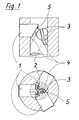
- the driving element a) consists of a simple "oblique groove with tooth piece". Due to the inclined undercut on one side only, it is possible to produce the beveled friction surface together with a groove or toothed piece in a single work step with a milling cutter package. This means that this driving element is ready when the friction surface is milled in other solutions.
- the driving elements b) and c) are based on the use of finished cylindrical pins or an easy to manufacture separate extruded profile.
- the main manufacturing advantage here lies in the fact that it is possible to work inexpensively with large tolerances and without special tools, without being functional impairment.
- the element a) requires very little space in the device due to its extreme structural simplicity. In addition, it can shrink together with the device without becoming sensitive. In contrast, the tapered friction surfaces can occupy a large amount. These are subjected to pressure during clamping and can therefore transmit greater forces, especially since the driving element is ideally located in the center.
- the grooves or bores in the piston can simultaneously be designed as grease channels, which form the connection between two grease spaces. With each clamping process, grease is pumped past the entrainment elements, for example from the upper piston space into a lower space that exists at a constriction point of the piston. The result is high efficiency and a long service life.
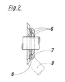
- FIG. 2 shows how easy it is to produce:
- a cone milling cutter package (6) creates an inclined friction surface (7) and toothed piece (8) of a clamping slide (9) in one milling process.
- it may also be sensible - which is not shown in the figure - to arrange two of these entrainment elements lying side by side in parallel, that can be made just as quickly.
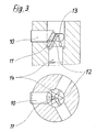
- Fig. 3 shows the same basic structure as Fig.1. The only difference is the shape of the entrainment elements, each consisting of a cylindrical pin (11) which is electrically punctured on a cocking slide (10) and a bore (12) receiving the latter with a longitudinal slot (13) in the piston (14).
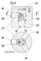
- the driving element according to the invention is formed by a separate part (15) with an "eight-section" and from two bores (16, 17) each made in the tension slide (18) and piston (19).
- the separate part (15) can consist of two dotted cylinder pins, or of the section of a profile strand. The latter possibility is shown here, the intermediate web (20) increasing the pendulum compensation ability of the element.
- This figure also shows the forced lubrication which exists between the upper grease space (21) and a lower grease space (22) at a constriction point (23) of the piston (19).
- the size of this lower grease chamber (22) is such that the volume of the entire grease area remains approximately the same in every position of the piston (19) and cocking slide (18).
- a flattening (24) of the part (15) creates a connection - and thus a fat channel - between the upper (21) and the lower (22) fat space.
Landscapes
- Engineering & Computer Science (AREA)
- Mechanical Engineering (AREA)
- Hydraulic Clutches, Magnetic Clutches, Fluid Clutches, And Fluid Joints (AREA)
- Vehicle Body Suspensions (AREA)
- Flanged Joints, Insulating Joints, And Other Joints (AREA)
- Wire Bonding (AREA)
- Jigs For Machine Tools (AREA)
- Clamps And Clips (AREA)
Priority Applications (3)
| Application Number | Priority Date | Filing Date | Title |
|---|---|---|---|
| AT89124045T ATE107555T1 (de) | 1989-12-28 | 1989-12-28 | Mitnahmeelement für zentrierspann- oder spannvorrichtungen. |
| DE58907966T DE58907966D1 (de) | 1989-12-28 | 1989-12-28 | Mitnahmeelement für Zentrierspann- oder Spannvorrichtungen. |
| EP89124045A EP0437638B1 (fr) | 1989-12-28 | 1989-12-28 | Elément d'entraînement pour dispositifs de centrage et de serrage |
Applications Claiming Priority (1)
| Application Number | Priority Date | Filing Date | Title |
|---|---|---|---|
| EP89124045A EP0437638B1 (fr) | 1989-12-28 | 1989-12-28 | Elément d'entraînement pour dispositifs de centrage et de serrage |
Publications (2)
| Publication Number | Publication Date |
|---|---|
| EP0437638A1 true EP0437638A1 (fr) | 1991-07-24 |
| EP0437638B1 EP0437638B1 (fr) | 1994-06-22 |
Family
ID=8202284
Family Applications (1)
| Application Number | Title | Priority Date | Filing Date |
|---|---|---|---|
| EP89124045A Expired - Lifetime EP0437638B1 (fr) | 1989-12-28 | 1989-12-28 | Elément d'entraînement pour dispositifs de centrage et de serrage |
Country Status (3)
| Country | Link |
|---|---|
| EP (1) | EP0437638B1 (fr) |
| AT (1) | ATE107555T1 (fr) |
| DE (1) | DE58907966D1 (fr) |
Cited By (2)
| Publication number | Priority date | Publication date | Assignee | Title |
|---|---|---|---|---|
| CN105965048A (zh) * | 2016-06-22 | 2016-09-28 | 陕西宝成航空仪表有限责任公司 | 新式涨力心轴 |
| WO2020200817A1 (fr) * | 2019-04-02 | 2020-10-08 | Röhm Gmbh | Broche de serrage |
Citations (5)
| Publication number | Priority date | Publication date | Assignee | Title |
|---|---|---|---|---|
| GB159405A (en) * | 1918-03-08 | 1921-03-03 | Alfred Raison | Improvements in chucks |
| DE3045536A1 (de) * | 1980-12-03 | 1982-07-01 | Fa. Wilhelm Blessing, 7302 Ostfildern | Vorrichtung zum zentrierten spannen eines werkstueck-spannfutters |
| EP0096285A1 (fr) * | 1982-06-08 | 1983-12-21 | Moshe Zloof | Mandrin à mâchoires |
| US4469288A (en) * | 1983-02-28 | 1984-09-04 | Double E Company Inc. | Expansible shaft with actuator retaining member and spherical bearing surface |
| GB2178984A (en) * | 1985-08-16 | 1987-02-25 | Kitagawa Iron Works Co | Chucks |
-
1989
- 1989-12-28 AT AT89124045T patent/ATE107555T1/de not_active IP Right Cessation
- 1989-12-28 DE DE58907966T patent/DE58907966D1/de not_active Expired - Lifetime
- 1989-12-28 EP EP89124045A patent/EP0437638B1/fr not_active Expired - Lifetime
Patent Citations (5)
| Publication number | Priority date | Publication date | Assignee | Title |
|---|---|---|---|---|
| GB159405A (en) * | 1918-03-08 | 1921-03-03 | Alfred Raison | Improvements in chucks |
| DE3045536A1 (de) * | 1980-12-03 | 1982-07-01 | Fa. Wilhelm Blessing, 7302 Ostfildern | Vorrichtung zum zentrierten spannen eines werkstueck-spannfutters |
| EP0096285A1 (fr) * | 1982-06-08 | 1983-12-21 | Moshe Zloof | Mandrin à mâchoires |
| US4469288A (en) * | 1983-02-28 | 1984-09-04 | Double E Company Inc. | Expansible shaft with actuator retaining member and spherical bearing surface |
| GB2178984A (en) * | 1985-08-16 | 1987-02-25 | Kitagawa Iron Works Co | Chucks |
Cited By (3)
| Publication number | Priority date | Publication date | Assignee | Title |
|---|---|---|---|---|
| CN105965048A (zh) * | 2016-06-22 | 2016-09-28 | 陕西宝成航空仪表有限责任公司 | 新式涨力心轴 |
| CN105965048B (zh) * | 2016-06-22 | 2017-12-29 | 陕西宝成航空仪表有限责任公司 | 新式涨力心轴 |
| WO2020200817A1 (fr) * | 2019-04-02 | 2020-10-08 | Röhm Gmbh | Broche de serrage |
Also Published As
| Publication number | Publication date |
|---|---|
| DE58907966D1 (de) | 1994-07-28 |
| EP0437638B1 (fr) | 1994-06-22 |
| ATE107555T1 (de) | 1994-07-15 |
Similar Documents
| Publication | Publication Date | Title |
|---|---|---|
| DE19739074B4 (de) | Sägeblatt und Verfahren zu seiner Herstellung | |
| DE2538139C2 (de) | Schraube | |
| DE3812150A1 (de) | Spiralverzahntes zerspanungswerkzeug | |
| DE69806320T2 (de) | Druckflüssigkeitsbetriebener Schlagmeschanismus | |
| EP1214536B1 (fr) | Procede pour la production d'un porte-satellites | |
| DE3340765C2 (fr) | ||
| DE1934339A1 (de) | Verfahren und Vorrichtung zum dauerhaften Verbinden von umlaufenden Teilen,wie Wellenteilen od.dgl.,mittels Kerbverzahnung | |
| EP1384535A1 (fr) | Dispositif d'arrachage | |
| WO2014184291A2 (fr) | Élément structural comprenant au moins deux parties soudées ensemble | |
| DE2601858B2 (de) | Stanzmaschine | |
| DE3742739C2 (fr) | ||
| EP0112437B1 (fr) | Outil pour un traitement précis et finissage de coupes cylindriques | |
| EP0548878B1 (fr) | Dispositif pour l'assemblage précis de deux pièces cylindrique, notamment pour une tige de porte-outil | |
| DE102007038254B4 (de) | Kupplungsglied für eine Mitnehmerkupplung und Herstellungsverfahren | |
| EP0437638A1 (fr) | Elément d'entraînement pour dispositifs de centrage et de serrage | |
| DE2851308A1 (de) | Vorrichtung zum einstemmen von lagerbuechsen | |
| DE69108096T2 (de) | Riemenscheibe. | |
| DE2601285C3 (de) | Vorrichtung für die spanlose Kaltverformung eines Rohlings in ein Werkstück mit Radialfortsätzen | |
| DE1625512A1 (de) | Praezisions-Vielnut- bzw. Kerbzahnverbindung | |
| DE102012206015A1 (de) | Schwingungsisolator und Verfahren dessen Herstellung | |
| EP0285704A2 (fr) | Système de serrage composé de plusieurs parties en particulier pour outils tournant rond | |
| DE2542346B2 (de) | Innenraeumwerkzeug, insbesondere zur herstellung von profilnuten | |
| AT17990U1 (de) | Eingriffselement und Spannsystem | |
| DE1477863A1 (de) | Bohrkopf fuer Tieflochbohrwerkzeuge | |
| DE102005012297B4 (de) | Schmiedemaschine |
Legal Events
| Date | Code | Title | Description |
|---|---|---|---|
| PUAI | Public reference made under article 153(3) epc to a published international application that has entered the european phase |
Free format text: ORIGINAL CODE: 0009012 |
|
| AK | Designated contracting states |
Kind code of ref document: A1 Designated state(s): AT BE CH DE ES FR GB GR IT LI LU NL SE |
|
| 17P | Request for examination filed |
Effective date: 19910813 |
|
| RBV | Designated contracting states (corrected) |
Designated state(s): AT BE CH DE ES FR GB IT LI NL |
|
| 17Q | First examination report despatched |
Effective date: 19921218 |
|
| GRAA | (expected) grant |
Free format text: ORIGINAL CODE: 0009210 |
|
| AK | Designated contracting states |
Kind code of ref document: B1 Designated state(s): AT BE CH DE ES FR GB IT LI NL |
|
| PG25 | Lapsed in a contracting state [announced via postgrant information from national office to epo] |
Ref country code: NL Effective date: 19940622 Ref country code: ES Free format text: THE PATENT HAS BEEN ANNULLED BY A DECISION OF A NATIONAL AUTHORITY Effective date: 19940622 Ref country code: BE Effective date: 19940622 |
|
| REF | Corresponds to: |
Ref document number: 107555 Country of ref document: AT Date of ref document: 19940715 Kind code of ref document: T |
|
| REF | Corresponds to: |
Ref document number: 58907966 Country of ref document: DE Date of ref document: 19940728 |
|
| ITF | It: translation for a ep patent filed | ||
| GBT | Gb: translation of ep patent filed (gb section 77(6)(a)/1977) |
Effective date: 19940906 |
|
| ET | Fr: translation filed | ||
| NLV1 | Nl: lapsed or annulled due to failure to fulfill the requirements of art. 29p and 29m of the patents act | ||
| PG25 | Lapsed in a contracting state [announced via postgrant information from national office to epo] |
Ref country code: AT Effective date: 19941228 |
|
| PLBE | No opposition filed within time limit |
Free format text: ORIGINAL CODE: 0009261 |
|
| STAA | Information on the status of an ep patent application or granted ep patent |
Free format text: STATUS: NO OPPOSITION FILED WITHIN TIME LIMIT |
|
| 26N | No opposition filed | ||
| REG | Reference to a national code |
Ref country code: GB Ref legal event code: IF02 |
|
| PGFP | Annual fee paid to national office [announced via postgrant information from national office to epo] |
Ref country code: CH Payment date: 20081222 Year of fee payment: 20 |
|
| PGFP | Annual fee paid to national office [announced via postgrant information from national office to epo] |
Ref country code: IT Payment date: 20081227 Year of fee payment: 20 |
|
| PGFP | Annual fee paid to national office [announced via postgrant information from national office to epo] |
Ref country code: FR Payment date: 20081216 Year of fee payment: 20 |
|
| PGFP | Annual fee paid to national office [announced via postgrant information from national office to epo] |
Ref country code: DE Payment date: 20081231 Year of fee payment: 20 |
|
| PGFP | Annual fee paid to national office [announced via postgrant information from national office to epo] |
Ref country code: GB Payment date: 20081219 Year of fee payment: 20 |
|
| REG | Reference to a national code |
Ref country code: CH Ref legal event code: PL |
|
| REG | Reference to a national code |
Ref country code: GB Ref legal event code: PE20 Expiry date: 20091227 |
|
| PG25 | Lapsed in a contracting state [announced via postgrant information from national office to epo] |
Ref country code: GB Free format text: LAPSE BECAUSE OF EXPIRATION OF PROTECTION Effective date: 20091227 |