EP0096285A1 - Mandrin à mâchoires - Google Patents
Mandrin à mâchoires Download PDFInfo
- Publication number
- EP0096285A1 EP0096285A1 EP83105101A EP83105101A EP0096285A1 EP 0096285 A1 EP0096285 A1 EP 0096285A1 EP 83105101 A EP83105101 A EP 83105101A EP 83105101 A EP83105101 A EP 83105101A EP 0096285 A1 EP0096285 A1 EP 0096285A1
- Authority
- EP
- European Patent Office
- Prior art keywords
- chuck
- housing
- jaw
- longitudinal axis
- drive cylinder
- Prior art date
- Legal status (The legal status is an assumption and is not a legal conclusion. Google has not performed a legal analysis and makes no representation as to the accuracy of the status listed.)
- Withdrawn
Links
- 230000001154 acute effect Effects 0.000 claims abstract description 10
- 238000010276 construction Methods 0.000 description 11
- 230000008878 coupling Effects 0.000 description 6
- 238000010168 coupling process Methods 0.000 description 6
- 238000005859 coupling reaction Methods 0.000 description 6
- 230000004048 modification Effects 0.000 description 4
- 238000012986 modification Methods 0.000 description 4
- 238000003754 machining Methods 0.000 description 2
- 230000013011 mating Effects 0.000 description 2
- 239000002184 metal Substances 0.000 description 2
- 208000027418 Wounds and injury Diseases 0.000 description 1
- 230000006378 damage Effects 0.000 description 1
- 230000007423 decrease Effects 0.000 description 1
- 230000000694 effects Effects 0.000 description 1
- 239000012530 fluid Substances 0.000 description 1
- 208000014674 injury Diseases 0.000 description 1
- 238000004519 manufacturing process Methods 0.000 description 1
- 239000002245 particle Substances 0.000 description 1
Images


Classifications
-
- B—PERFORMING OPERATIONS; TRANSPORTING
- B23—MACHINE TOOLS; METAL-WORKING NOT OTHERWISE PROVIDED FOR
- B23B—TURNING; BORING
- B23B31/00—Chucks; Expansion mandrels; Adaptations thereof for remote control
- B23B31/02—Chucks
- B23B31/10—Chucks characterised by the retaining or gripping devices or their immediate operating means
- B23B31/12—Chucks with simultaneously-acting jaws, whether or not also individually adjustable
- B23B31/16—Chucks with simultaneously-acting jaws, whether or not also individually adjustable moving radially
- B23B31/16233—Jaws movement actuated by oblique surfaces of a coaxial control rod
- B23B31/16237—Details of the jaws
-
- Y—GENERAL TAGGING OF NEW TECHNOLOGICAL DEVELOPMENTS; GENERAL TAGGING OF CROSS-SECTIONAL TECHNOLOGIES SPANNING OVER SEVERAL SECTIONS OF THE IPC; TECHNICAL SUBJECTS COVERED BY FORMER USPC CROSS-REFERENCE ART COLLECTIONS [XRACs] AND DIGESTS
- Y10—TECHNICAL SUBJECTS COVERED BY FORMER USPC
- Y10T—TECHNICAL SUBJECTS COVERED BY FORMER US CLASSIFICATION
- Y10T279/00—Chucks or sockets
- Y10T279/12—Chucks or sockets with fluid-pressure actuator
- Y10T279/1274—Radially reciprocating jaws
- Y10T279/1291—Fluid pressure moves jaws via mechanical connection
-
- Y—GENERAL TAGGING OF NEW TECHNOLOGICAL DEVELOPMENTS; GENERAL TAGGING OF CROSS-SECTIONAL TECHNOLOGIES SPANNING OVER SEVERAL SECTIONS OF THE IPC; TECHNICAL SUBJECTS COVERED BY FORMER USPC CROSS-REFERENCE ART COLLECTIONS [XRACs] AND DIGESTS
- Y10—TECHNICAL SUBJECTS COVERED BY FORMER USPC
- Y10T—TECHNICAL SUBJECTS COVERED BY FORMER US CLASSIFICATION
- Y10T279/00—Chucks or sockets
- Y10T279/19—Radially reciprocating jaws
- Y10T279/1973—Wedge actuated
-
- Y—GENERAL TAGGING OF NEW TECHNOLOGICAL DEVELOPMENTS; GENERAL TAGGING OF CROSS-SECTIONAL TECHNOLOGIES SPANNING OVER SEVERAL SECTIONS OF THE IPC; TECHNICAL SUBJECTS COVERED BY FORMER USPC CROSS-REFERENCE ART COLLECTIONS [XRACs] AND DIGESTS
- Y10—TECHNICAL SUBJECTS COVERED BY FORMER USPC
- Y10T—TECHNICAL SUBJECTS COVERED BY FORMER US CLASSIFICATION
- Y10T279/00—Chucks or sockets
- Y10T279/19—Radially reciprocating jaws
- Y10T279/1986—Jaws
Definitions
- the present invention relates to multiple-jaw chucks, such as those used to clamp a workpiece during a machining operation.
- a popular type of multiple-jaw chuck widely used today comprises a housing and a drive cylinder pneumatically driven parallel to the longitudinal axis of the housing and coupled to a plurality of chuck jaws to drive them radially towards and away from the housing longitudinal axis in order to clamp or disengage the workpiece.
- This popular type of chuck includes a rib-and-slot coupling of T-configuration between the drive cylinder and each of the chuck jaws, and a further rib-and-slot guide -also of T-configuration to guide the movement of the chuck jaws while they are driven by the cylinder.
- Such known constructions however, have a number of disadvantages.
- T-configuration for the rib-and-slot coupling and for the guide involves high-precision, time-consuming machine operations which increase the manufacturing cost of the chuck.
- metal-to-metal contact faces it is very difficult, no matter how high the precision, to preclude the entry of dirt between the metal faces particularly at the sharp corners, which dirt increases the wear on the parts and shortens their useful life.
- An object of the present invention is to provide a multiple-jaw chuck having advantages in the above respects.
- a multiple-jaw chuck comprising a housing and a drive cylinder driven parallel to the longitudinal axis of the housing and driving a plurality of chuck jaws towards and away from said housing longitudinal axis
- said drive cylinder includes an axially-extending pin for each of said chuck jaws which pins are fixed to the drive cylinder at an acute angle to the longitudinal axis of the housing, each of said chuck jaws including a bore formed at the same acute angle to the longitudinal axis of the housing and receiving said pin, such that each of said chuck jaws is driven radially towards and away from said longitudinal axis of the housing when the drive cylinder is driven parallel to the longitudinal axis of the housing.
- each of the pins is fixed within an axially-extending cavity formed in the drive cylinder for each of the chuck jaws.
- a multiple-jaw chuck comprising a housing and a drive cylinder driven parallel to the longitudinal axis of the housing and driving a plurality of chuck jaws towards and away from said housing longitudinal axis, characterized in that each of said chuck jaws includes an inner drive arm coupled to the drive cylinder, and an outer workpiece-engaging arm carried by its respective drive arm for movement therewith to engage and disengage the workpiece when the chuck jaw is driven radially with respect to the longitudinal axis of the housing, each of said drive arms being of substantially cylindrical configuration and being movable in a bore of corresponding cylindrical configuration formed in the housing.
- the novel chuck constructed in accordance with the foregoing features provides a number of important advantages over the above-mentioned known constructions.
- the novel chuck constructed in accordance with the foregoing features does not require the costly, time-consuming and high-precision machining operations of the previously-mentioned chucks, and therefore can be produced at substantially lower cost.
- the mating surfaces between the chuck jaws and the housing through which the jaws move include less sharp corners than the known constructions, which substantially decreases the possibility for the entry of dirt particles between them and thereby contributes to a much longer useful life for the chuck.
- the pressurized fluid supply e.g. air
- Such an interruption in the force applied to the chuck may result not only in the workpiece being suddenly released, but may also result in the workpiece being set into motion at a high velocity, which could cause a serious injury.
- a number of complicated arrangements have been provided to impart a self-locking construction to multiple-jaw chucks wherein the jaws would automatically lock in place in the event of an interruption in the pressurized air supply, but these self-locking arrangements are usually of complicated and expensive construction.
- a chuck comprising a housing 2 carrying three chuck jaws, each generally designated 3, movable radially with respect to the housing 2, i.e., towards and away from its longitudinal axis LA, in order to engage or disengage a workpiece WP.
- chucks may be pneumatically driven by a drive cylinder 4 (Fig. 2) disposed within housing 2 and coupled to the three chuck jaws 3 so as to drive them radially towards and away from the housing axis LA when the drive cylinder4 is driven parallel to the housing axis.
- housing 2 is of cylindrical shape and is formed with a central cylindrical bore 21 whose outer end is closed by a cover plate 22 (Fig. 1) flush with the respective face of the housing.
- Drive cylinder 4 is received within housing bore 21 and is driven, e.g. by a known pneumatic drive (not shown), parallel to the axis LA of the housing 2 and of its bore 21.
- Housing 2 is further formed with three equally-spaced cylindrical bores 25 extending in the radial direction, there being one such bore 25 for each of the chuck jaws 3. As shown particularly in Fig. 2, each cylindrical bore 25 joins a rectangular slot 26 formed in the outer face of housing 2. Slot 26 serves as a keying slot for the respective chuck jaw 3, as will be described more particularly below, and has a width of approximately one-half the diameter of its respective bore 25.
- Each of the three chuck jaws 3 is constituted of two main members, namely an inner drive arm 31 movable within its bore 25 of the housing 2, and an outer workpiece-engaging arm 32 projecting outwardly of the housing for engaging the workpiece.
- the workpiece-engaging arm 32 is coupled to its drive arm 31 by means of threaded fasteners, shown schematically at 33, passing through openings in both of these members.
- the inner face of the workpiece-engaging arm 32 coupled to the drive arm 31 is formed with a keying rib 34 receivable within keying slot 26 of the housing 2, for constraining the movement of the respective chuck jaw to a rectilinear movement, i.e., for preventing the chuck jaw from rotating within its housing bore.25.
- keying rib 34 is made of two sections, 34a and 34b, separated by a central tranverse slot or recess 34c; and the confronting face of the drive arm 31 of the respective chuck jaw is formed with a transversely-extending rib 35 received within recess 34c.
- rib 35 is received within recess 34c and serves, together with the two keying rib sections 34a and 34b on the inner face of the workpiece-engaging arm 32, to assure that the chuck jaw may move only in the radial direction and cannot rotate within the cylindrical bore 25.
- each chuck jaw includes an extension 36 having a bore 37 extending axially of the chuck and'formed at an acute angle to its longitudinal axis 4.
- Extension 36 is coupled to the drive cylinder 4, the latter being formed with a cavity or recess 41 for such extension in each of the chuck jaws 3.
- a pin 42 is fixed within each cavity 41 between a pair of bores 43, 44 formed through the cavity end walls. Bores 43 and 44, and the pin 42 secured within them, form the same acute angle as bore 37 in the chuck drive arm extension 36.
- the chuck jaws 3 are coupled to the drive cylinder 4 by means of the pins 42 which are passed through bores 43, 44 in the drive cylinder and bore 37 in the end extensions 36 of the chuck jaws.
- one of the bores in the drive cylinder 4 e.g., bore 43
- the coupling pin 42 may be passed through the larger drive cylinder bore, then through bore 37 of the respective chuck drive arm 31 and then through the smaller-diameter bore of the drive cylinder 4, which latter bore wedges and firmly fixes the pin in place within the respective cavity 41 of the cylinder.
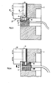
- each cavity 41 of the drive cylinder has a width substantially equal to that of the respective extension 36 of the chuck jaw, but a length substantially larger than the extension, as shown particularly in Figs. 3 and 4, to permit the drive cylinder 4 to move axially with respect to the chuck jaws 3.
- Figs. 3 and 4 illustrate the manner in which drive cylinder 4 moves the chuck jaws 3 in the radial direction to engage or disengage the workpiece.
- the drive cylinder 4 when the drive cylinder 4 is in its outermost (leftmost) position, the chuck jaws 3 are in their radially outermost position disengaging the workpiece; and when the drive cylinder 4 is driven rightwardly, as shown in Fig. 4, its pin 42 received within bore 37 of each chuck jaw 3 causes the jaws to move radially inwardly to engage the workpiece.
- the magnitude of radial movement of the chuck jaws 3 in relation to the axial movement of the drive cylinder 4 depends on the angle formed by the coupling pins 42 to the longitudinal axis of the chuck. Preferably, this acute angle is between 5-15 degrees, an angle of approximately 10 degrees having been found highly satisfactory for most applications.
- the multiple-jaw chuck would include several difforent types of workpiece-engaging arms, corresponding to arm 32 in Figs. 1-4, removably attachable to the drive arms 31 of the chuck jaws, for selective use according to the particular type of workpiece to be gripped by the chuck.
- the keying rib on each chuck jaw movable within the keying slot of the chuck housing for constraining the movement of the chuck jaw to a rectilinear path is formed on the inner face of the workpiece-engaging arm (32), but it will be appreciated that it could also be formed on the drive arm (31) of the respective chuck jaw.
- Fig. 5 illustrates such an arrangement wherein this I keying rib, therein designated 134, is integrally formed with the drive arm 131 of the chuck jaw, rather than with the workpiece-engaging arm 132.
- the keying rib 134 in Fig. 5 could otherwise be of the same construction as keying rib 34 in Figs.
- Fig. 6 illustrates a further modification wherein the drive cylinder, therein designated 104 is provided, with a cavity 141 accommodating two coupling pins 142a, 142b in parallel, side-by-side relationship, instead of one pin. These two pins extend at an acute angle to their longitudinal axis and are received within two inclined bores (not shown) in the end extension of each chuck jaw, corresponding to bore 37 in end extension 36 of each chuck jaw in the Figs 1-4 embodiment as described above.
Landscapes
- Engineering & Computer Science (AREA)
- Mechanical Engineering (AREA)
- Gripping On Spindles (AREA)
Applications Claiming Priority (2)
| Application Number | Priority Date | Filing Date | Title |
|---|---|---|---|
| IL66006 | 1982-06-08 | ||
| IL66006A IL66006A (en) | 1982-06-08 | 1982-06-08 | Jaw-chuck |
Publications (1)
| Publication Number | Publication Date |
|---|---|
| EP0096285A1 true EP0096285A1 (fr) | 1983-12-21 |
Family
ID=11053551
Family Applications (1)
| Application Number | Title | Priority Date | Filing Date |
|---|---|---|---|
| EP83105101A Withdrawn EP0096285A1 (fr) | 1982-06-08 | 1983-05-24 | Mandrin à mâchoires |
Country Status (4)
| Country | Link |
|---|---|
| US (1) | US4488731A (fr) |
| EP (1) | EP0096285A1 (fr) |
| JP (1) | JPS591107A (fr) |
| IL (1) | IL66006A (fr) |
Cited By (1)
| Publication number | Priority date | Publication date | Assignee | Title |
|---|---|---|---|---|
| EP0437638A1 (fr) * | 1989-12-28 | 1991-07-24 | Rudolf Kohlert | Elément d'entraînement pour dispositifs de centrage et de serrage |
Families Citing this family (3)
| Publication number | Priority date | Publication date | Assignee | Title |
|---|---|---|---|---|
| US6299179B1 (en) * | 1995-03-22 | 2001-10-09 | R. S. R. Adtec Ltd. | Fluid actuated chuck |
| CN103231084A (zh) * | 2013-05-21 | 2013-08-07 | 方式 | 楔式动力卡盘 |
| JP6411619B1 (ja) * | 2017-12-01 | 2018-10-24 | 株式会社北川鉄工所 | チャック及びその製造方法 |
Citations (5)
| Publication number | Priority date | Publication date | Assignee | Title |
|---|---|---|---|---|
| US2695176A (en) * | 1952-02-21 | 1954-11-23 | Union Mfg Co | Pneumatic operated chuck |
| US3515400A (en) * | 1966-08-25 | 1970-06-02 | Edward J Jendry | Wear compensated lathe chuck |
| US3542386A (en) * | 1967-07-03 | 1970-11-24 | Forkardt Paul Kg | Power-operated jaw chuck |
| US4000907A (en) * | 1974-02-01 | 1977-01-04 | Equipements De Machines-Outils Spemo | Chucks for machine tools, such as lathes and grinding machines |
| GB2000456A (en) * | 1977-07-02 | 1979-01-10 | Forkardt Paul Kg | Clamping chucks |
Family Cites Families (5)
| Publication number | Priority date | Publication date | Assignee | Title |
|---|---|---|---|---|
| US1305138A (en) * | 1919-05-27 | mcclellan | ||
| US2023869A (en) * | 1933-11-22 | 1935-12-10 | Sundstrand Machine Tool Co | Work supports for machine tools |
| US3171663A (en) * | 1960-07-15 | 1965-03-02 | James A Stark | Machine tool chucking device |
| BE758988A (fr) * | 1969-11-17 | 1971-04-30 | Morawski London T | Mandrin de machine-outil pour pieces irregulieres |
| US4264112A (en) * | 1979-08-06 | 1981-04-28 | Lee Controls, Inc. | Floating pillow blocks |
-
1982
- 1982-06-08 IL IL66006A patent/IL66006A/xx unknown
- 1982-09-08 US US06/415,925 patent/US4488731A/en not_active Expired - Fee Related
-
1983
- 1983-05-24 EP EP83105101A patent/EP0096285A1/fr not_active Withdrawn
- 1983-06-07 JP JP58100343A patent/JPS591107A/ja active Pending
Patent Citations (5)
| Publication number | Priority date | Publication date | Assignee | Title |
|---|---|---|---|---|
| US2695176A (en) * | 1952-02-21 | 1954-11-23 | Union Mfg Co | Pneumatic operated chuck |
| US3515400A (en) * | 1966-08-25 | 1970-06-02 | Edward J Jendry | Wear compensated lathe chuck |
| US3542386A (en) * | 1967-07-03 | 1970-11-24 | Forkardt Paul Kg | Power-operated jaw chuck |
| US4000907A (en) * | 1974-02-01 | 1977-01-04 | Equipements De Machines-Outils Spemo | Chucks for machine tools, such as lathes and grinding machines |
| GB2000456A (en) * | 1977-07-02 | 1979-01-10 | Forkardt Paul Kg | Clamping chucks |
Cited By (1)
| Publication number | Priority date | Publication date | Assignee | Title |
|---|---|---|---|---|
| EP0437638A1 (fr) * | 1989-12-28 | 1991-07-24 | Rudolf Kohlert | Elément d'entraînement pour dispositifs de centrage et de serrage |
Also Published As
| Publication number | Publication date |
|---|---|
| JPS591107A (ja) | 1984-01-06 |
| IL66006A (en) | 1986-02-28 |
| IL66006A0 (en) | 1982-09-30 |
| US4488731A (en) | 1984-12-18 |
Similar Documents
| Publication | Publication Date | Title |
|---|---|---|
| SU1382396A3 (ru) | Устройство дл закреплени издели или инструмента дл режущих станков | |
| EP0294348B1 (fr) | Assemblage d'outil, composants d'outil et méthode pour assembler ces composants | |
| US4858938A (en) | Two piece collet with interlocking collet segments | |
| US4726268A (en) | Clamping apparatus for holding a toolholder shank | |
| US2816770A (en) | Tool holder and adapter | |
| GB1536738A (en) | Rotary percussive apparatus | |
| EP0466027A1 (fr) | Dispositif de changement d'outil pour robot | |
| US4488731A (en) | Multiple-jaw chuck | |
| JPH08501256A (ja) | 機械スピンドルをツールホルダーと接続するためのクランプ装置 | |
| AU753925B2 (en) | Toolholder assembly | |
| US5464231A (en) | Chuck with jaws having curved engagement surfaces | |
| US4640518A (en) | Jaw locking means for lathe chucks | |
| JPH08229713A (ja) | チャック | |
| JP2004025429A (ja) | モジュールに収容された工具保持アームの接続装置 | |
| US3868120A (en) | Chuck | |
| GB2125712A (en) | Boring tool | |
| DK0563727T3 (da) | Indretning til overføring af drejningsmoment | |
| US4710077A (en) | Locking tool holder | |
| US6966728B1 (en) | Toolholder assembly | |
| JPS61182709A (ja) | 工作機械のチヤツク | |
| CA1288936C (fr) | Mandrin de filiere pour mamelons de tuyauterie | |
| US4641414A (en) | Pallet for seating interchangeable clamping jaws of a chuck | |
| US3424467A (en) | Chuck construction | |
| US3420539A (en) | Manually operable chuck for lathes and other machine tools | |
| RU2047425C1 (ru) | Бесключевой сверлильный патрон |
Legal Events
| Date | Code | Title | Description |
|---|---|---|---|
| PUAI | Public reference made under article 153(3) epc to a published international application that has entered the european phase |
Free format text: ORIGINAL CODE: 0009012 |
|
| AK | Designated contracting states |
Designated state(s): AT BE CH DE FR GB IT LI NL SE |
|
| 17P | Request for examination filed |
Effective date: 19840426 |
|
| 19U | Interruption of proceedings before grant |
Effective date: 19860423 |
|
| 19W | Proceedings resumed before grant after interruption of proceedings |
Effective date: 20210201 |
|
| GRAJ | Information related to disapproval of communication of intention to grant by the applicant or resumption of examination proceedings by the epo deleted |
Free format text: ORIGINAL CODE: EPIDOSDIGR1 |
|
| GRAL | Information related to payment of fee for publishing/printing deleted |
Free format text: ORIGINAL CODE: EPIDOSDIGR3 |
|
| INTC | Intention to grant announced (deleted) | ||
| 18W | Application withdrawn |
Effective date: 20210201 |