EP0437639B1 - Dichtung für die Verbindung von zwei Stücken eines Förderbandes und eine solche Dichtung aufweisende Verbindung - Google Patents
Dichtung für die Verbindung von zwei Stücken eines Förderbandes und eine solche Dichtung aufweisende Verbindung Download PDFInfo
- Publication number
- EP0437639B1 EP0437639B1 EP89403477A EP89403477A EP0437639B1 EP 0437639 B1 EP0437639 B1 EP 0437639B1 EP 89403477 A EP89403477 A EP 89403477A EP 89403477 A EP89403477 A EP 89403477A EP 0437639 B1 EP0437639 B1 EP 0437639B1
- Authority
- EP
- European Patent Office
- Prior art keywords
- staples
- seal
- rows
- conveyor belt
- knuckles
- Prior art date
- Legal status (The legal status is an assumption and is not a legal conclusion. Google has not performed a legal analysis and makes no representation as to the accuracy of the status listed.)
- Expired - Lifetime
Links
- 239000000463 material Substances 0.000 claims description 4
- 239000002184 metal Substances 0.000 claims description 4
- 239000011324 bead Substances 0.000 description 6
- 239000003245 coal Substances 0.000 description 2
- 239000013013 elastic material Substances 0.000 description 2
- 238000009434 installation Methods 0.000 description 2
- 238000007789 sealing Methods 0.000 description 2
- 230000006835 compression Effects 0.000 description 1
- 238000007906 compression Methods 0.000 description 1
- 230000006866 deterioration Effects 0.000 description 1
- 230000000694 effects Effects 0.000 description 1
- 238000000465 moulding Methods 0.000 description 1
- 229920003052 natural elastomer Polymers 0.000 description 1
- 229920001194 natural rubber Polymers 0.000 description 1
- 229920003051 synthetic elastomer Polymers 0.000 description 1
- 239000005061 synthetic rubber Substances 0.000 description 1
Images

Classifications
-
- F—MECHANICAL ENGINEERING; LIGHTING; HEATING; WEAPONS; BLASTING
- F16—ENGINEERING ELEMENTS AND UNITS; GENERAL MEASURES FOR PRODUCING AND MAINTAINING EFFECTIVE FUNCTIONING OF MACHINES OR INSTALLATIONS; THERMAL INSULATION IN GENERAL
- F16G—BELTS, CABLES, OR ROPES, PREDOMINANTLY USED FOR DRIVING PURPOSES; CHAINS; FITTINGS PREDOMINANTLY USED THEREFOR
- F16G3/00—Belt fastenings, e.g. for conveyor belts
- F16G3/02—Belt fastenings, e.g. for conveyor belts with series of eyes or the like, interposed and linked by a pin to form a hinge
-
- Y—GENERAL TAGGING OF NEW TECHNOLOGICAL DEVELOPMENTS; GENERAL TAGGING OF CROSS-SECTIONAL TECHNOLOGIES SPANNING OVER SEVERAL SECTIONS OF THE IPC; TECHNICAL SUBJECTS COVERED BY FORMER USPC CROSS-REFERENCE ART COLLECTIONS [XRACs] AND DIGESTS
- Y10—TECHNICAL SUBJECTS COVERED BY FORMER USPC
- Y10T—TECHNICAL SUBJECTS COVERED BY FORMER US CLASSIFICATION
- Y10T24/00—Buckles, buttons, clasps, etc.
- Y10T24/16—Belt fasteners
- Y10T24/1608—Hinged
- Y10T24/1632—Sheet metal knuckles, common pintle
-
- Y—GENERAL TAGGING OF NEW TECHNOLOGICAL DEVELOPMENTS; GENERAL TAGGING OF CROSS-SECTIONAL TECHNOLOGIES SPANNING OVER SEVERAL SECTIONS OF THE IPC; TECHNICAL SUBJECTS COVERED BY FORMER USPC CROSS-REFERENCE ART COLLECTIONS [XRACs] AND DIGESTS
- Y10—TECHNICAL SUBJECTS COVERED BY FORMER USPC
- Y10T—TECHNICAL SUBJECTS COVERED BY FORMER US CLASSIFICATION
- Y10T24/00—Buckles, buttons, clasps, etc.
- Y10T24/16—Belt fasteners
- Y10T24/1672—Butt connected belt ends
Definitions
- the present invention relates to devices used for joining two sections of a conveyor belt. It relates more specifically to the junction devices constituted by two rows of staples of general U-shaped section, which are intended to be fixed astride the ends of these two sections to be then joined by a hinge pin threaded in the nested knuckles formed by these staples.
- Document FR-A-2 593 872 describes such a device according to the preamble of claims 1 and 3.
- British patent GB-A-634,028 describes a joining device in which provision is made for the addition of a bead of compressible material between the edge of each end of a conveyor belt and the hinge pin engaged in the knuckles of the two rows of staples. Because of their compressibility, these beads then conform to the shape of the parts opposite the axis of articulation. However, by the very fact that they are simply threaded in the gap existing between the junction axis and the edge of one of the ends of the conveyor belt, these beads are not really immobilized in place. They can therefore move. In addition, this absence of immobilization has the effect that these beads can be twisted on themselves during the articulation of the corresponding junction device, which causes rapid deterioration thereof.
- Such a bead must have a thickness determined as a function of that of the corresponding conveyor belt. It is therefore not possible to use the same type of bead for carpets of very different thicknesses.
- the present joint is perfectly immobilized after fixing the staples of the corresponding junction device in place, because the clamps for fixing these staples are caused to pass through one and the other of the lateral branches of this joint. Furthermore, it can be used on conveyor belts of varying thickness. Indeed the loop provided on the lamellae forming the middle branch of this joint allows them to extend more or less or to retract on themselves, depending on whether the conveyor belt is very thick or on the contrary not very thick. Moreover, the presence of the cutouts provided between these strips gives great flexibility to the middle branch of the joint and precisely allows it to be able to be extended or retracted, and this depending on the thickness of the carpet more or less corresponding carrier.
- the present invention also relates to the joining devices of the type recalled above which are provided with two seals as defined above.
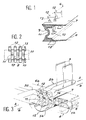
- the seal shown in FIG. 1 is intended to be added to a device for joining the ends of two sections 1a and 1b of a conveyor belt.
- This device is of the type comprising two rows of metal staples 2a, 2b of general U shape which are arranged astride the ends of one and the other of these two sections. These staples form knuckles, respectively 3a and 3b, which are therefore oriented in the opposite direction. These knuckles are offset to be nested with each other so as to constitute a kind of hinge inside which is engaged a pin 4 of junction constituted by a section of wire rope.
- the staples of the two rows are fixed by metal studs 5, the points of which are folded down after having successively passed through a first branch of one of the staples 2a or 2b, the corresponding section 1a or 1b of the conveyor belt, and the opposite branch of the same clip.
- the seal shown in Figure 1, and which is designated by the general reference 6, has a generally U-shaped section.
- this seal can be placed astride the end of one of the sections of the carpet conveyor, below the staples of the corresponding row.
- the two lateral branches 7 and 8 then form two strips which are placed against one and the other faces of the corresponding section of the conveyor belt. So when the studs are pushed in 5 these two arms are crossed by these studs.
- the middle branch 9 of this joint has a series of transverse cuts 10 delimiting as many narrow strips 11. However, each of these strips forms a loop projecting towards the side opposite to that provided for the junction axis 4.
- each of the lateral branches 7 and 8 of the latter carries a series of projecting teeth 12. Each of these is placed very exactly below one of the cutouts 10 of the middle branch 9. It should be noted that the face of the teeth 12, which is turned in the direction of the junction axis 4, has a profile 13 of concave shape.
- the joint thus formed is produced by molding in an elastic material, for example in natural or synthetic rubber.
- This joint has a very great flexibility. This flexibility is obviously accentuated at the location of the middle branch 9 due to the presence of the very large number of transverse cutouts 10. Consequently, the intermediate lamellae 11 have very great flexibility and can thus deform very easily.
- the projecting teeth 12 of this joint are intended to be placed inside the intervals 14 existing between two successive knuckles 3a or 3b of the corresponding row of staples.
- the cutouts 10 of the joint considered are therefore themselves placed between two successive knuckles of this row of staples.
- the cutouts 10 and the strips 11 of the two seals 6a and 6b equipping one and the other of these two rows are themselves offset like the knuckles 3a and 3b of these staples. Consequently, these are the ends of the knuckles of the opposing row of staples which are placed inside the cutouts 10 of a joint considered 6a or 6b, and which come into contact with the curved face 13 of the projecting teeth 12 of this joint.
- the lamellae 11 of this same seal are situated opposite the knuckles 3a or 3b of the corresponding row of staples. Consequently, these strips are applied directly against the junction axis 4, on the side diametrically opposite to that of the end of the knuckle of one of the staples of the corresponding row.
- the axis 4 is completely wrapped between the knuckle 3a or 3b of the staples of one of the rows and one of the strips 11 of the joint belonging to the same row d 'staples (see Figures 4a and 4b).
- the main advantage of the seal according to the invention lies in the fact that it can be used on sections of conveyor belt of greater or lesser thickness. This results from the fact that the loop form, provided for the strips 11, allows the latter to be more or less extended depending on the case or on the contrary retracted on themselves. However, as already indicated, these strips have a great flexibility due to the presence of the numerous cutouts 10 existing in the middle branch 9 of the joint.
- FIGS. 4a and 4b illustrate the use of the seal according to the invention on conveyor belts having different thicknesses E1 and E2.
- this simply causes an elongation of the loop formed by the strips 11 (case of FIG. 4a).
- this results in a more or less accentuated compression, "in accordion", of the loop formed by the strips 11 (case of FIG. 4b).
- This is therefore an essential advantage compared to the sealing joints provided hitherto on junction devices of the type in question.
- this seal By the very fact of the design of this seal, it can be mounted in advance inside the staples of the same row.
- the projecting teeth 12 of this joint are then engaged between the intervals existing between the knuckles of the row considered of staples. This is sufficient to ensure that the seals are kept in place until the corresponding row of staples is used and fixed in place, the section of the projecting teeth 12 being dimensioned to ensure a certain wedging in place.
- the seal according to the invention is used with staples, each of which has two knuckles.
- this seal could just as easily be used with staples each provided with a single knuckle, or on the contrary with a larger number of knuckles.
- the details of the shape of the seal according to the invention can be modified as a function of the characteristics of the clips of the joining device.
- the invention also relates to joining devices comprising two rows of staples of the type in question and two seals attached to one and the other of these two rows. These devices can be used for joining the sections of a carpet used to transport loose materials, for example coal, gravel, etc.
Landscapes
- Engineering & Computer Science (AREA)
- General Engineering & Computer Science (AREA)
- Mechanical Engineering (AREA)
- Belt Conveyors (AREA)
- Structure Of Belt Conveyors (AREA)
Claims (3)
- Dichtung (6, 6a, 6b) zur Abdichtung der Verbindungsstelle von zwei Teilstücken (1a, 1b) eines Transportbandes mittels zweier Reihen von Metallklammern (2a, 2b), im allgemeinen in U-Form, die auf den Enden der zwei zu verbindenden Teilstücke übergreifend aufgesetzt sind und die ihrerseits durch einen Verbindungsbolzen (4) zusammengefügt sind, der in die durch diese Klammern gebildeten sich überlappenden Scharnieraugen (3a, 3b) eingeführt ist, wobei diese Dichtung aus einem Profil aus einem elastischen Material mit einem im allgemeinen U-förmigen Querschnitt besteht, so daß sie auch übergreifend auf das Ende eines zu verbindenden Teilstücks aufgesteckt werden kann und dies unter den Klammern der entsprechenden Reihe, dadurch gekennzeichnet, daß:- der mittlere Teil (9) dieser Dichtung (6) eine Reihe von quergerichteten Ausstanzungen (10) aufweist, die geeignet sind, das Ende des Scharnierauges (3a, 3b) einer der Verbindungsklammern (2a, 2b) der gegenwirkenden Reihe aufzunehmen, wobei diese Ausstanzungen ebensoviele schmale Lamellen (11) abgrenzen, die dazu bestimmt sind, sich gegen den Verbindungsbolzen (4) an der genau entgegengesetzten Seite des Endes des Scharnierauges (3a, 3b) der einen der Klammern der entsprechenden Reihe zu drücken,- jede der so vorgesehenen schmalen Lamellen (11) eine Schleife formt, die an der entgegengesetzten Seite zu der, die dazu bestimmt ist, gegen den Verbindungsbolzen (4) zu drücken, einen Vorsprung bildet, wobei diese Schleife mehr oder weniger zusammengedrückt oder auseinandergezogen sein kann, je nach der Stärke des entsprechenden Transportbandes.
- Dichtung nach Anspruch 1, dadurch gekennzeichnet, daß nahe ihrer Verbindung mit dem mittleren Teil (9) jeder der seitlichen Teile (7, 8) eine Reihe von hervorspringenden Zähne (12) trägt, die jede senkrecht zu einer quergerichteten Ausstanzung (10) des mittleren Teils gelegen ist, wobei diese hervorspringenden Zähne dazu bestimmt sind, in die zwischen zwei aufeinanderfolgenden Scharnieraugen (3a, 3b) der entsprechenden Reihe von Klammern bestehenden Zwischenräume angeordnet zu werden.
- Vorrichtung zur Verbindung von zwei Teilstücken (1a, 1b) eines Transportbandes mittels zweier Reihen von Metallklammern (2a, 2b) der zwei zu verbindenden Teilstücke und die ihrerseits durch einen Verbindungsbolzen (4) zusammengefügt sind, der in die durch diese Klammern gebildeten überlappenden Scharnieraugen (3a, 3b) eingeführt ist, dadurch gekennzeichnet, daß diese Vorrichtung außerdem zwei Dichtungen (6, 6a, 6b) nach einem der vorangehenden Ansprüche aufweist.
Priority Applications (3)
| Application Number | Priority Date | Filing Date | Title |
|---|---|---|---|
| EP89403477A EP0437639B1 (de) | 1989-12-14 | 1989-12-14 | Dichtung für die Verbindung von zwei Stücken eines Förderbandes und eine solche Dichtung aufweisende Verbindung |
| DE89403477T DE68910694T2 (de) | 1989-12-14 | 1989-12-14 | Dichtung für die Verbindung von zwei Stücken eines Förderbandes und eine solche Dichtung aufweisende Verbindung. |
| US07/626,883 US5097944A (en) | 1989-12-14 | 1990-12-13 | Seal providing a tight joint between two sections of a conveyor belt and a coupling device fitted with said seal |
Applications Claiming Priority (1)
| Application Number | Priority Date | Filing Date | Title |
|---|---|---|---|
| EP89403477A EP0437639B1 (de) | 1989-12-14 | 1989-12-14 | Dichtung für die Verbindung von zwei Stücken eines Förderbandes und eine solche Dichtung aufweisende Verbindung |
Publications (2)
| Publication Number | Publication Date |
|---|---|
| EP0437639A1 EP0437639A1 (de) | 1991-07-24 |
| EP0437639B1 true EP0437639B1 (de) | 1993-11-10 |
Family
ID=8203013
Family Applications (1)
| Application Number | Title | Priority Date | Filing Date |
|---|---|---|---|
| EP89403477A Expired - Lifetime EP0437639B1 (de) | 1989-12-14 | 1989-12-14 | Dichtung für die Verbindung von zwei Stücken eines Förderbandes und eine solche Dichtung aufweisende Verbindung |
Country Status (3)
| Country | Link |
|---|---|
| US (1) | US5097944A (de) |
| EP (1) | EP0437639B1 (de) |
| DE (1) | DE68910694T2 (de) |
Families Citing this family (7)
| Publication number | Priority date | Publication date | Assignee | Title |
|---|---|---|---|---|
| DE4110818C1 (de) * | 1991-04-04 | 1992-09-17 | Mato Maschinen- Und Metallwarenfabrik Curt Matthaei Gmbh & Co Kg, 6050 Offenbach, De | |
| US5236079A (en) * | 1991-06-05 | 1993-08-17 | Mato Maschinen-Und Metallwarenfabrik Curt Matthaei Gmbh & Co Kg | Belt fastener arrangement |
| FR2701300B1 (fr) * | 1993-02-09 | 1995-03-31 | Aser Sarl | Dispositif de jonctionnement pour bande transporteuse. |
| US5360103A (en) * | 1993-08-11 | 1994-11-01 | Loosli Curtis G | Quick splice for belt conveyor |
| EP0651178B1 (de) * | 1993-10-29 | 1997-01-15 | Goro S.A. | Riemenverbinder |
| US6627045B2 (en) * | 2001-10-09 | 2003-09-30 | Albany International Corp. | Seam for a corrugator belt |
| DE102011082267A1 (de) * | 2011-09-07 | 2013-03-07 | Aktiebolaget Skf | Tragefördermittellagereinheit |
Family Cites Families (15)
| Publication number | Priority date | Publication date | Assignee | Title |
|---|---|---|---|---|
| GB634028A (en) * | 1948-03-08 | 1950-03-15 | Mastabar Belt Fastener Company | Improvements relating to joints for conveyor and transmission belts |
| DE833280C (de) * | 1949-09-30 | 1952-03-06 | Curt Matthaei | Haltekamm zum Einspannen von V-foermigen Drahthaken fuer Riemen- und Transportbandverbindungen waehrend des Einpressens |
| DE826723C (de) * | 1950-07-01 | 1952-01-03 | Hermine Seifert Geb Haegele | Schutzkappe fuer Transportband-Verbinder |
| US2971256A (en) * | 1954-10-26 | 1961-02-14 | Leflon Henri | Fasteners for conveyor belts and the like |
| FR2240636A5 (de) * | 1973-08-08 | 1975-03-07 | Rhone Poulenc Textile | |
| FR2372353A1 (fr) * | 1976-11-30 | 1978-06-23 | Goro | Procede de jonction des extremites d'un tapis transporteur ou similaire, et tapis dont les extremites sont ainsi assemblees |
| DE2920461C2 (de) * | 1979-05-21 | 1981-09-03 | Mato Maschinen- Und Metallwarenfabrik Curt Matthaei Gmbh & Co Kg, 6050 Offenbach | Verbinderstreifen für Fördergurte |
| US4344209A (en) * | 1979-10-22 | 1982-08-17 | Scapa Dryers, Inc. | In-line clipper seam |
| FR2566477B1 (fr) * | 1984-06-26 | 1987-08-21 | Goro Sa | Axe flexible pour la reunion et l'articulation des agrafes de jonction d'un tapis transporteur |
| FR2574510B1 (fr) * | 1984-12-11 | 1987-01-09 | Goro Sa | Dispositif destine a assurer la liaison articulee de deux series complementaires d'agrafes de jonction |
| DE3446427A1 (de) * | 1984-12-20 | 1986-07-10 | Mato Maschinen- Und Metallwarenfabrik Curt Matthaei Gmbh & Co Kg, 6050 Offenbach | Foerderbandverbinderstreifen |
| US4815587A (en) * | 1985-01-24 | 1989-03-28 | Flexible Steel Lacing Company | Fastener for harvester belts |
| FR2593872B3 (fr) * | 1986-01-31 | 1988-03-18 | Goro Sa | Dispositif de jonction des extremites d'un tapis transporteur |
| FR2624940A1 (fr) * | 1987-12-17 | 1989-06-23 | Goro Sa | Axe de jonction pour l'accouplement des extremites d'un tapis transporteur ou similaire |
| US4996750A (en) * | 1989-06-26 | 1991-03-05 | Flexible Steel Lacing Company | Wire belt fastener |
-
1989
- 1989-12-14 DE DE89403477T patent/DE68910694T2/de not_active Expired - Fee Related
- 1989-12-14 EP EP89403477A patent/EP0437639B1/de not_active Expired - Lifetime
-
1990
- 1990-12-13 US US07/626,883 patent/US5097944A/en not_active Expired - Fee Related
Also Published As
| Publication number | Publication date |
|---|---|
| DE68910694T2 (de) | 1994-05-05 |
| DE68910694D1 (de) | 1993-12-16 |
| US5097944A (en) | 1992-03-24 |
| EP0437639A1 (de) | 1991-07-24 |
Similar Documents
| Publication | Publication Date | Title |
|---|---|---|
| EP0911565B1 (de) | Schnellverbindung zur Verbindung von starren Rohren in einem Anschlussstück | |
| BE1005346A5 (fr) | Collier ameliore pour tuyau. | |
| FR2555695A1 (fr) | Derailleur avant comportant un element de protection ou capuchon pour le ressort de rappel | |
| FR2713305A1 (fr) | Dispositif de raccord rapide pour tubulures d'échangeur de chaleur. | |
| FR2626660A1 (fr) | Dispositif d'assemblage pour un ensemble echangeur de chaleur/raccord tubulaire | |
| FR2522086A1 (fr) | Collier de serrage pour tuyau flexible | |
| CA1130902A (fr) | Appareil de commutation d'impulsions haute tension avec une precision de l'ordre de la picoseconde | |
| FR2687886A1 (fr) | Fixation pour ensemble de boitier. | |
| EP0437639B1 (de) | Dichtung für die Verbindung von zwei Stücken eines Förderbandes und eine solche Dichtung aufweisende Verbindung | |
| FR2857709A1 (fr) | Mousqueton a deux doigts opposes | |
| EP0720706B1 (de) | Verbindungdvorrichtung für fördergut | |
| FR2685434A1 (fr) | Dispositif de raccord rapide pour la liaison etanche entre eux de deux tubes ou tuyaux rigides ou semi-rigides. | |
| EP2352928A1 (de) | Befestiger mit dichtungsscheibe | |
| EP2201265A1 (de) | Verbesserte verbindungsvorrichtung für förderbänder | |
| FR2526278A1 (fr) | Fermeture a glissiere comportant des elements d'accouplement discrets perfectionnes | |
| CH644312A5 (fr) | Chaine pour pneumatique. | |
| FR2511583A1 (fr) | Bande d'accrochage de fermeture a glissiere etanche | |
| FR2908177A1 (fr) | Collier double de serrage et procede de montage | |
| EP0371853B1 (de) | Halteschiene für Musterbuch | |
| EP0324290A1 (de) | Kupplungsstab zum Verbinden der Enden eines Transportbandes oder dgl. | |
| FR2593872A1 (fr) | Dispositif de jonction des extremites d'un tapis transporteur | |
| FR2574510A1 (fr) | Dispositif destine a assurer la liaison articulee de deux series complementaires d'agrafes de jonction | |
| FR2817924A1 (fr) | Collier pour la fixation rapide de cables sur un chemin de cables | |
| FR2635261A1 (fr) | Dispositif pour l'appareillage post-operatoire d'une colostomie laterale | |
| EP0156736A1 (de) | Profilierter Dichtungsstreifen, insbesondere für Fahrzeugschiebetüren |
Legal Events
| Date | Code | Title | Description |
|---|---|---|---|
| PUAI | Public reference made under article 153(3) epc to a published international application that has entered the european phase |
Free format text: ORIGINAL CODE: 0009012 |
|
| AK | Designated contracting states |
Kind code of ref document: A1 Designated state(s): DE FR GB |
|
| RIN1 | Information on inventor provided before grant (corrected) |
Inventor name: SCHICK, JEAN-FRANCOIS |
|
| 17P | Request for examination filed |
Effective date: 19911109 |
|
| 17Q | First examination report despatched |
Effective date: 19930407 |
|
| GRAA | (expected) grant |
Free format text: ORIGINAL CODE: 0009210 |
|
| AK | Designated contracting states |
Kind code of ref document: B1 Designated state(s): DE FR GB |
|
| REF | Corresponds to: |
Ref document number: 68910694 Country of ref document: DE Date of ref document: 19931216 |
|
| GBT | Gb: translation of ep patent filed (gb section 77(6)(a)/1977) |
Effective date: 19940209 |
|
| PLBE | No opposition filed within time limit |
Free format text: ORIGINAL CODE: 0009261 |
|
| STAA | Information on the status of an ep patent application or granted ep patent |
Free format text: STATUS: NO OPPOSITION FILED WITHIN TIME LIMIT |
|
| 26N | No opposition filed | ||
| PGFP | Annual fee paid to national office [announced via postgrant information from national office to epo] |
Ref country code: GB Payment date: 19941206 Year of fee payment: 6 |
|
| PGFP | Annual fee paid to national office [announced via postgrant information from national office to epo] |
Ref country code: DE Payment date: 19951208 Year of fee payment: 7 |
|
| PG25 | Lapsed in a contracting state [announced via postgrant information from national office to epo] |
Ref country code: GB Effective date: 19951214 |
|
| PGFP | Annual fee paid to national office [announced via postgrant information from national office to epo] |
Ref country code: FR Payment date: 19951228 Year of fee payment: 7 |
|
| GBPC | Gb: european patent ceased through non-payment of renewal fee |
Effective date: 19951214 |
|
| PG25 | Lapsed in a contracting state [announced via postgrant information from national office to epo] |
Ref country code: FR Effective date: 19970829 |
|
| PG25 | Lapsed in a contracting state [announced via postgrant information from national office to epo] |
Ref country code: DE Effective date: 19970902 |
|
| REG | Reference to a national code |
Ref country code: FR Ref legal event code: ST |