EP0437646B1 - Trieuse - Google Patents
Trieuse Download PDFInfo
- Publication number
- EP0437646B1 EP0437646B1 EP90100728A EP90100728A EP0437646B1 EP 0437646 B1 EP0437646 B1 EP 0437646B1 EP 90100728 A EP90100728 A EP 90100728A EP 90100728 A EP90100728 A EP 90100728A EP 0437646 B1 EP0437646 B1 EP 0437646B1
- Authority
- EP
- European Patent Office
- Prior art keywords
- tray
- sorting
- sheet
- ejecting
- mode
- Prior art date
- Legal status (The legal status is an assumption and is not a legal conclusion. Google has not performed a legal analysis and makes no representation as to the accuracy of the status listed.)
- Expired - Lifetime
Links
- 238000001514 detection method Methods 0.000 claims description 19
- 230000004044 response Effects 0.000 description 5
- 230000007246 mechanism Effects 0.000 description 3
- 230000001143 conditioned effect Effects 0.000 description 2
- 238000010586 diagram Methods 0.000 description 2
- 238000006073 displacement reaction Methods 0.000 description 2
- 230000000694 effects Effects 0.000 description 2
- 230000002441 reversible effect Effects 0.000 description 2
- 230000002238 attenuated effect Effects 0.000 description 1
- 210000000078 claw Anatomy 0.000 description 1
- 230000005611 electricity Effects 0.000 description 1
- 238000007689 inspection Methods 0.000 description 1
- 238000012423 maintenance Methods 0.000 description 1
- 239000000463 material Substances 0.000 description 1
- 239000002184 metal Substances 0.000 description 1
- 238000000034 method Methods 0.000 description 1
- 230000008450 motivation Effects 0.000 description 1
- 238000002360 preparation method Methods 0.000 description 1
- 230000003068 static effect Effects 0.000 description 1
- 230000001360 synchronised effect Effects 0.000 description 1
- 230000007723 transport mechanism Effects 0.000 description 1
- 230000001960 triggered effect Effects 0.000 description 1
Images




Classifications
-
- B—PERFORMING OPERATIONS; TRANSPORTING
- B65—CONVEYING; PACKING; STORING; HANDLING THIN OR FILAMENTARY MATERIAL
- B65H—HANDLING THIN OR FILAMENTARY MATERIAL, e.g. SHEETS, WEBS, CABLES
- B65H39/00—Associating, collating, or gathering articles or webs
- B65H39/10—Associating articles from a single source, to form, e.g. a writing-pad
- B65H39/11—Associating articles from a single source, to form, e.g. a writing-pad in superposed carriers
-
- B—PERFORMING OPERATIONS; TRANSPORTING
- B65—CONVEYING; PACKING; STORING; HANDLING THIN OR FILAMENTARY MATERIAL
- B65H—HANDLING THIN OR FILAMENTARY MATERIAL, e.g. SHEETS, WEBS, CABLES
- B65H2405/00—Parts for holding the handled material
- B65H2405/10—Cassettes, holders, bins, decks, trays, supports or magazines for sheets stacked substantially horizontally
- B65H2405/11—Parts and details thereof
- B65H2405/111—Bottom
- B65H2405/1111—Bottom with several surface portions forming an angle relatively to each other
-
- B—PERFORMING OPERATIONS; TRANSPORTING
- B65—CONVEYING; PACKING; STORING; HANDLING THIN OR FILAMENTARY MATERIAL
- B65H—HANDLING THIN OR FILAMENTARY MATERIAL, e.g. SHEETS, WEBS, CABLES
- B65H2408/00—Specific machines
- B65H2408/10—Specific machines for handling sheet(s)
- B65H2408/11—Sorters or machines for sorting articles
- B65H2408/112—Sorters or machines for sorting articles with stationary location in space of the bins and in-feed member movable from bin to bin
Definitions
- the present invention relates generally to a sorting machine and more specifically to a sorting machine which is suited for use with a printer or copy machine.
- a sorting machine of the type wherein a plurality of trays (bin) are immovably disposed in a fixed vertical array and the sheets of printed matter are selectively transported to a preselected tray by a suitable sheet transport mechanism, is known.
- US-A-4,836,529 shows an example of such a type of sorting machine.
- the above object is achieved by an arrangement wherein, during non-sorting modes, a selectively movable ejection unit which can be moved up and down along one side of the tray bin, is set in a predetermined position above an uppermost tray and in a position wherein the distance between the ejection unit and the upper tray is notably larger than the distance the ejection unit is normally located above the other trays during sorting and group modes.
- this high setting is achieved by rotating a Geneva cam which forms part of the ejection unit motivation arrangement, twice instead of the normal single rotation usually executed during a sorting or group mode of operation.
- the sheet of printed matter is pressed against a plurality of transfer belts by a spring strip arrangement which is designed to exert a predetermined force on one face of the sheets undergoing transportation.
- This ensures that the sheet moves synchronously with the transfer belts and is securely delivered to the ejection unit.
- This unit is arranged so that, after ejecting a sheet into one tray during a sorting mode, it is moved and positioned with respect to the next selected tray ready for ejection thereinto. Each time the eject ion unit is moved, it is moved through the same distance and then held stationary during sheet ejection.
- the ejection unit When a non-sorting mode is selected the ejection unit is moved directly to the upper tray and then set in a position with respect to the tray so that the distance between it and the upper tray is notably larger than that which is established between the ejection unit and the trays below the top one during the sorting mode.
- a larger number of sheets than possible with the above discussed prior art arrangement can be collected on the upper tray without incident or the need to break the delivery into smaller lots.
- Figs. 1 to 6 show details of sorting device to which the present invention is applied.
- the numeral 1 generally denotes a sorting section while the numeral 2 generally denotes a feed section 2.
- the feed section 2 comprises a sheet feed opening 3, a plurality of spaced sheet transfer belts 4 which pass over drive and idler pulleys 5A, 5B, and a feed motor 6 which is operatively connected to the shaft on which the drive pulleys are mounted.
- the feed section 1 is hingedly mounted and arranged so that, in the case of jamming due to sheet becoming crumpled or the like during either transportation or ejection; or alternatively, when a maintenance inspection is to be carried out, the feed section can be selectively unlatched and swung apart from the sorting section 1 to facilitate ready access to the mechanisms which are disposed therewithin.
- an open/closed sensor 46 is disposed in the sorting section 1 and operatively arranged with a manually operable latch arrangement (not shown) which is arranged to releasably lock the two sections together, and arranged to detect the two sections being properly latched together.
- the sorting and feed sections 1, 2 are supported on a common mobile base 1A.
- the front corner of the base 1A is formed with an angled portion 1B which is designed to permit an operator stand closer to the sorting device and to more readily remove sheets from the vertical array of trays 7.
- An electric stapler 100 is mounted on a shoulder portion of a case 8 which encloses the sorting section 1.
- the case 8 in which the sorting section is housed includes a side wall or frame section 8A on which the trays 7 are fixedly supported.
- a ejection unit 11 is operatively mounted on a support frame 12 which is arranged to be slidable up and down within the case.
- a plurality of eject rollers 13 are rotatably supported on the frame 12 in a manner to cooperate with corresponding idler rollers 14.
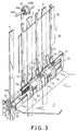
- Upwardly extending guide fingers or claws 15 are arranged on either side of each of the eject rollers 13 as shown in Fig. 3.
- a plurality of strips 16 of springy material are each wound on a spool 16B.
- each of the spools 16B are rotatably supported on a shaft 16A which extends laterally across the upper interior of the case 8.
- the strips 16 are arranged to re-wind back onto the spools 16B with a predetermined and essentially constant force irrespective of how much is wound off.
- the spring strips 16 (as they will be referred to hereinafter) have smooth surfaces which exhibit a low coefficient of friction.
- the lower ends of the spring strips 16 are connected to the support frame 12 and are arranged to extend in an alternate or staggered relationship with respect to the transfer belts 4 which cause a sheets which is being moved through the sorting section 1, to be pressed against the surfaces of the transfer belts 4 in a manner which ensures that it will be moved in the desired synchronous manner therewith.
- the guide fingers 15 are arranged to extend into the path of the sheets being transferred and guide the same away from the transfer belts against which they have been held, between the eject and idler rollers 13 and 14 and toward a tray 7.
- Fig. 3 shows a sheet 20 being guided toward a tray 7 by the eject unit 11.
- Intermeshing gears 21, 21 establish a drive connection between a pulley 23 which is mounted on a shaft 22 and held in drive contact with the surface of one of the transfer belts 4, and a shaft 13A on which the eject rollers 13 are mounted.
- the arrangement defines a step-up gearing which rotates the eject and idler rollers 13, 14 in a manner wherein the surface speed of the rollers is greater than the transfer belts 4. This arrangement tends securely pick up the sheet and obviate jamming.
- Curved metal fasteners 24 are fixedly mounted on the frame 12. These fasteners 24 serve to interconnect the lower ends of the spring strips 16 to the frame 12 and hold the same in the desired relationship with respect to the transfer belts 4.
- a brush 25 for removing static electricity is mounted on the frame 12 and arranged to sweep over the surface of the sheets as they pass between the eject and idler rollers 13, 14.
- Fig. 4 shows details of the mechanism via which the eject unit 11 is selectively raised and lowered within the sorting section 1, and selectively brought in the appropriate position with respect to a selected tray.
- guide pins 30A and 30B which extend from either side of the eject unit 11 are slidably received in vertical guide slots 31 fixed to the side frame of the case 8.
- the eject unit 11 is operatively connected to a sprocket 32 by a sprocket chain 33 (note the actual connection between the ejection unit 11 and the sprocket chain 33 is not shown).
- the ejection unit 11 is raised and lowered in accordance with the rotation of the sprocket 33.
- the lower end of the chain passes over a sprocket 34 (see Fig. 5).
- a Geneva wheel 35 which is formed with five engagement slots 35A is mounted on the shaft of the sprocket 34 and arranged to cooperate with a Geneva cam 36 having a single drive pin 36A.
- the Geneva cam 36 is arranged to be driven by a reversible tray motor 37 by way of a non-illustrated drive connection.
- the Geneva cam 36 for each rotation of the Geneva cam 36 the Geneva wheel is induced to undergo 1/5 of a rotation.
- the sprocket chain 33 provides an operatively connection between the sprocket 34 and the ejection unit 11 in a manner wherein the rotation of the sprocket 34 is translated in vertical linear movement of the ejection unit 11. It will be noted that the ratio of movement to non-movement with the Geneva cam/wheel arrangement is 1:4
- the control of the tray motor 37 when the sorting device is switched to the non-sorting modes is such that it is induced to undergo two sequential rotations. This induces the situation wherein, such as shown in Fig. 4, the ejection unit 11 assumes a position wherein its outlet is located a position which adjacent the very upper portion of the opening through which sheets are ejected into the tray (in this case tray 7A) and which is considerably higher with respect to the floor of the tray 7A as compared with the position which is assumed in the case of the sorting mode.
- the feed opening 3 includes a guide plate 40 with which an incoming sheet detection sensor 41 is disposed.
- This sensor is arranged to detect a sheet being fed into the feed opening 3 and takes the form of a suitable light source, a photo diode and a suitable light path interrupting arrangement.
- the feed motor 6 When a sheet is detected by the incoming sheet detection sensor 41 as being inserted into the feed opening 3, the feed motor 6 is energized. This induces the transfer belts 4 to be driven and brings about the situation wherein the sheet which has triggered the sensor, is drawn in between the belts 4 and an idler roller 42.
- a control unit 50 (shown in Fig. 6) is arranged to indicate that jamming of the sheet has occurred and to issue a command which stops the operation of the feed motor 6.
- the sheet detection sensor arrangement 43 comprises a light source 43A and a light responsive element 43B such as a photo diode.
- a light beam 43C is produced by the light source 43A and aimed at the light responsive element 43B. As shown in Fig. 2, this light beam 43C is produced in a manner so that it extends between two adjacent guide fingers 15. When a sheet is being deflected by these fingers 15 and is sliding toward the eject rollers 13, 14, the beam 43C is interrupted.
- the present invention is not limited to this particular sensor location and a similar arrangement can alternatively be disposed on the tray side of the ejection unit 11 if so desired.
- An ejection unit position sensor 44 is arranged above the ejection unit 11 and arranged to produce a signal indicative of the ejection unit 11 having assumed a predetermined position.
- this predetermined position is one in which the ejection unit 11 has assumed a position suited for ejecting into the upper tray 7A.
- a cam rotation sensor 45 is disposed in the lower portion of the sorting section 1 proximate the Geneva cam 36 and arranged to sense the completion of each rotation of the same. As the rotation of the Geneva cam has a predetermined relationship with the position of the ejection unit 11, this sensor serves in effect to monitor the position of the ejection unit with respect to the trays 7.
- the cam rotation sensor 45 comprises a source of light, a shutter plate which is mounted on the Geneva cam 36 and a light sensitive photo diode.
- the ejection unit 11 can be taken to mean that the ejection unit 11 has been into position with respect to the next tray and that the next sheet can be ejected.
- Fig. 6 shows the arrangement of the control unit 50 in block diagram form.
- the control unit 50 includes a microprocessor which includes input boards 50A which are arranged to received input signals from a mode switch unit 51 along with signals from the above mentioned sensors 41 and 43 to 46.
- the mode switch unit 51 is arranged to enable manual switching between a sorting mode, a non-sorting mode and a group mode, and to generate signals indicative of the selected setting. Alternatively, these signals can be derived from the host machine to which the sorting machine is connected.
- the output board 50B of the microcomputer is operatively connected with the above mentioned feed and tray motors 6, 37 via a feed motor driver circuit 6A and a tray motor driver circuit 37A, respectively.
- An LED type sorting device status indicating lamp unit 52 is also connected to the output board 50B.
- a timer 50C and ROM 50D are operatively connected with a CPU 50E via suitable bus arrangements.
- the operation of the above described arrangement is such that when the device is switched on, the CPU 50E is subject to an initialization which results in the tray motor 37 being energized in a manner which moves the ejection unit 11 up toward the predetermined position wherein it is situated to eject sheets into the upper tray 7A of the tray array. Upon reaching the upper tray position, the ejection unit position sensor 44 issues a signal indicative of the same and the movement of the unit 11 is halted. Under these conditions the sorting device is conditioned for non-sorting operation.
- the status indicating lamp unit 52 is energized to suitably indicate that all of the ejected sheets will be ejected and collected on the same tray (in this case the upper tray 7A).
- the incoming sheet detection sensor 41 assumes a high level (ON) indicating that a sheet has been fed into the feed opening 3
- the signal which is produced by this sensor is fed to the CPU 50E via the input board 50A.
- the feed motor driver 6A In response to this calculations are performed in the CPU and result in the output of signals to the feed motor driver 6A via the output board 50B.
- the feed motor 6 is energized and the sheet is transferred to the ejection unit 11 and then ejected into the upper tray 7A.
- the control program which is being run in the CPU is designed to determine that the supply of sheets has been finished and the feed motor 6 is de-energized.
- the displacement of the ejection unit 11 with respect to the upper tray 7A into which the sheets are to be ejected during the non-sorting mode is twice that which occurs during sorting and group modes (which will be discussed later) in this embodiment. It is also possible that the displacement of the ejection unit 11 with respect to the upper tray 7A during non-sorting mode is an integer multiple such as 3 or 4 times that possible during the sorting and group modes.
- the ejection unit 11 is moved toward the appropriate ejection position with respect to tray 7B (Viz., the second tray from the top) which is designated to be the top or first tray during the sorting mode.
- the status indicating lamp unit 52 is energized to indicate that the sorting device has been conditioned to produce the sorting mode.
- the movement of the ejection unit 11 is such that, following the signal from ejection unit position sensor 44 assuming a high level (ON) the system awaits the cam rotation sensor 45 to indicate that the Geneva cam 36 has completed two rotations. It should be noted that the two rotations are necessary to lower the ejection unit 11 from the high non-sorting position to that suited for ejection into tray 7B.
- the feed motor 6 When the first sheet is detect by sensor 41 as having been received in the feed opening 3, the feed motor 6 is energized and the transfer belts 4 are induced to move. Under these conditions, the sheet is carried between the belt and the roller 42, and transferred up to the upper idler pulley 5B. From this position the direction of travel is reversed and the sheet is induced to descend while being held against the faces of the transfer belts by the spring strips 16. Upon reaching the guide fingers 15 of the ejection unit 11 the sheet is guided away from the transfer belts and caused to pass between the ejection and idler rollers 13, 14. Under the influence of the rotating rollers 13, 14 the sheet is ejected into tray 7B.
- the ejection unit 11 is moved via a single rotation of the Geneva cam 36, toward the position required for ejecting the second sheet. During this mode the second sheet is ejected into tray 7C.
- the tray motor 6 is energized to rotate in direction which is the reverse of that induced during the sorting of the first round of sheets. This brings about the situation wherein the ejection unit 11 is moved stagewisely back from the last ejection position back towards tray 7B.
- the jam detecting process is basically similar to that employed during the non-sorting mode. However, in this instance the time from which the incoming sheet detection sensor 41 detects a sheet in the feed opening 3, to the time the sheet detection sensor arrangement 43 produces a high level signal, is varied from 3.2 - 4.8 seconds depending on the position of the ejection unit 11 and the distance through which a sheet must be moved before reaching the ejection unit 11.
- the ejection unit 11 is moved to tray 7B and at the same time the status indicating lamp unit 52 is energized in a manner to indicate the instant selection.
- the movement of the ejection unit 11 during this mode is the same as that of the sorting mode.
- the feed motor 6 is energized and the sheet is transferred to tray 7B which is also used as the top tray in this mode.
- the ejection unit 11 is moved one step down via a single rotation of the Geneva cam 36, into a position ready ejecting the next round of sheets into tray 7C.
Landscapes
- Collation Of Sheets And Webs (AREA)
Claims (7)
- Une machine de tri comprenant :
un ensemble de plateaux de réception (7) qui Sont disposés en un assemblage vertical fixe avec un écartement prédéterminé entre eux, chacun de ces plateaux de réception ayant une entrée par laquelle des feuilles peuvent être éjectées sur le plateau;
des moyens (11) pouvant se déplacer le long des entrées des plateaux de réception pour éjecter une feuille (20) sur les plateaux de réception (7);
des moyens (4, 6) pour transférer une feuille (20) vers les moyens d'éjection (11);
des moyens (33-37) pour déplacer de façon intermittente les moyens d'éjection (11); et
des moyens pour détecter un mode de fonctionnement prédéterminé, comprenant un mode de non-tri,
caractérisée par
des moyens qui réagissent à la détection du mode de non-tri par les moyens de détection en déplaçant les moyens d'éjection (11) vers un plateau supérieur (7A) parmi les plateaux de réception (7), et en plaçant les moyens d'éjection (11) à une distance au-dessus du plateau supérieur (7A) qui est supérieure et égale à des multiples entiers de l'écartement prédéterminé; et
des moyens qui réagissent à la détection d'un mode de tri par les moyens de détection en déplaçant les moyens d'éjection (11) vers un second plateau (7B) à partir du plateau supérieur parmi les plateaux de réception (7), ce qui fait que le plateau supérieur (7A) n'est pas utilisé dans le mode de tri. - Une machine de tri selon la revendication 1, caractérisée en ce que les moyens de transfert (4, 6) comprennent :
une courroie de transfert (4);
une lame à ressort (16) qui applique la surface d'une feuille (20) contre la courroie de transfert (4), la lame à ressort (16) ayant une surface lisse, et cette lame à ressort (16) ayant son extrémité inférieure reliée aux moyens d'éjection (11) et son extrémité supérieure reliée à une structure qui rétracte la lame (16) de façon élastique. - Un dispositif de tri selon la revendication 1 ou 2, caractérisé en ce que les moyens d'éjection (11) comprennent :
un élément de support (12);
un galet d'éjection (13) qui est monté de façon tournante sur l'élément de support (12);
un galet libre (14) qui est monté sur l'élément de support (12), en contact avec le galet d'éjection (13), et qui est entraîné de façon à tourner sous l'effet de la rotation du galet d'éjection (13); et
un élément de guidage (15) qui est monté sur l'élément de support (12) et qui guide la feuille (20) qui passe entre le galet d'éjection (13) et le galet libre (14), en direction d'une entrée de plateau. - Une machine de tri selon la revendication 3, caractérisée en ce qu'elle comprend en outre :
un axe (13A) sur lequel est monté le galet d'éjection (13);
une poulie (23) qui est en contact avec la courroie de transfert (4) de façon à être entraînée par cette dernière; et
des roues dentées (21) qui accouplent fonctionnellement la poulie (23) et l'axe (13A). - Une machine de tri selon l'une quelconque des revendications 1 à 4, caractérisée en ce que les moyens de déplacement (33-37) comprennent:
un moteur;
une came pour croix de Malte (36) qui est accouplée au moteur de façon à être entraînée par ce dernier;
une croix de Malte (35) ayant des encoches (35A) disposées à des intervalles angulaires égaux, en liaison fonctionnelle avec la came pour croix de Malte (36);
une roue à chaîne (34), cette roue à chaîne (34) étant accouplée à la croix de Malte (35) pour être entraînée par cette dernière;
une chaîne (33), cette chaîne (33) étant associée fonctionnellement à la roue à chaîne (34) et accouplée aux moyens d'éjection (11). - Une machine de tri selon la revendication 5, caractérisée en ce que la came pour croix de Malte (36) et la croix de Malte (35) sont conçues de façon qu'une révolution de la came pour croix de Malte (36) déplace les moyens d'éjection (11) sur une distance qui est égale à l'écartement entre les entrées des plateaux (7).
- Une machine de tri selon l'une quelconque des revendications 4 à 6, caractérisée en ce que la poulie (23) est accouplée au galet d'éjection (13) par l'intermédiaire de roues dentées (21), de façon que le galet d'éjection (13) ait une vitesse de surface supérieure à la vitesse de surface de la courroie de transfert (4).
Priority Applications (3)
| Application Number | Priority Date | Filing Date | Title |
|---|---|---|---|
| US07/464,436 US5048819A (en) | 1990-01-15 | 1990-01-12 | Sorting machine having an uppermost tray which is only used in the non-sorting mode |
| DE69008145T DE69008145T2 (de) | 1990-01-15 | 1990-01-15 | Sortiermaschine. |
| EP90100728A EP0437646B1 (fr) | 1990-01-15 | 1990-01-15 | Trieuse |
Applications Claiming Priority (1)
| Application Number | Priority Date | Filing Date | Title |
|---|---|---|---|
| EP90100728A EP0437646B1 (fr) | 1990-01-15 | 1990-01-15 | Trieuse |
Publications (2)
| Publication Number | Publication Date |
|---|---|
| EP0437646A1 EP0437646A1 (fr) | 1991-07-24 |
| EP0437646B1 true EP0437646B1 (fr) | 1994-04-13 |
Family
ID=8203495
Family Applications (1)
| Application Number | Title | Priority Date | Filing Date |
|---|---|---|---|
| EP90100728A Expired - Lifetime EP0437646B1 (fr) | 1990-01-15 | 1990-01-15 | Trieuse |
Country Status (3)
| Country | Link |
|---|---|
| US (1) | US5048819A (fr) |
| EP (1) | EP0437646B1 (fr) |
| DE (1) | DE69008145T2 (fr) |
Families Citing this family (6)
| Publication number | Priority date | Publication date | Assignee | Title |
|---|---|---|---|---|
| DE4009731A1 (de) * | 1990-03-27 | 1991-10-02 | Helmut Steinhilber | Sortiergeraet zur ablage von blattfoermigen aufzeichnungstraegern |
| US5342034A (en) * | 1993-04-27 | 1994-08-30 | Xerox Corporation | Mailbox/compiler architecture |
| JP3869863B2 (ja) * | 1993-12-28 | 2007-01-17 | キヤノン株式会社 | 画像形成システム及びその制御方法、並びに画像形成装置及びその制御方法 |
| JP3554631B2 (ja) * | 1996-05-13 | 2004-08-18 | ニスカ株式会社 | シート分配装置のシート束押出し構造 |
| JP3561082B2 (ja) * | 1996-05-13 | 2004-09-02 | ニスカ株式会社 | ステープラ付きシート分配装置 |
| JP3556424B2 (ja) * | 1996-05-13 | 2004-08-18 | ニスカ株式会社 | ステープラ付きシート分配装置 |
Family Cites Families (8)
| Publication number | Priority date | Publication date | Assignee | Title |
|---|---|---|---|---|
| US4204727A (en) * | 1979-05-03 | 1980-05-27 | Xerox Corporation | Multimode reproducing apparatus |
| US4548403A (en) * | 1981-11-18 | 1985-10-22 | Minolta Camera Kabushiki Kaisha | Sorter |
| JPS58183564A (ja) * | 1982-04-16 | 1983-10-26 | Toshiba Corp | 用紙の区分収納装置 |
| JPS6088969A (ja) * | 1983-10-22 | 1985-05-18 | Canon Inc | ソート装置 |
| JPS60202059A (ja) * | 1984-03-27 | 1985-10-12 | Sharp Corp | コピ−用紙収容ソ−タ |
| US4842264A (en) * | 1986-09-09 | 1989-06-27 | Ikegami Tsushinki Co., Ltd. | Sorting machine |
| US4836529A (en) * | 1986-09-09 | 1989-06-06 | Ikegami Tsushinki Co., Ltd. | Sorting machine |
| EP0631201B1 (fr) * | 1987-07-30 | 1998-10-28 | Canon Kabushiki Kaisha | Dispositif de tri de feuilles |
-
1990
- 1990-01-12 US US07/464,436 patent/US5048819A/en not_active Expired - Lifetime
- 1990-01-15 EP EP90100728A patent/EP0437646B1/fr not_active Expired - Lifetime
- 1990-01-15 DE DE69008145T patent/DE69008145T2/de not_active Expired - Fee Related
Also Published As
| Publication number | Publication date |
|---|---|
| DE69008145T2 (de) | 1994-10-13 |
| DE69008145D1 (de) | 1994-05-19 |
| US5048819A (en) | 1991-09-17 |
| EP0437646A1 (fr) | 1991-07-24 |
Similar Documents
| Publication | Publication Date | Title |
|---|---|---|
| EP0393589B1 (fr) | Appareil de délivrance de papier en continu | |
| US4456235A (en) | Bottom-up stacker | |
| US4095781A (en) | Currency dispensing apparatus | |
| US5121911A (en) | Finisher for an image forming apparatus | |
| EP0439032B1 (fr) | Trieuse | |
| US5048819A (en) | Sorting machine having an uppermost tray which is only used in the non-sorting mode | |
| EP0259829B1 (fr) | Machine de triage | |
| US4066255A (en) | Document transport system | |
| US4611800A (en) | Sheet separator apparatus for recirculating feeder | |
| US4819931A (en) | Sorting apparatus | |
| US3936042A (en) | Sheet feeding devices | |
| EP0611718A1 (fr) | Dispositif pour empiler des feuilles | |
| EP0259830B1 (fr) | Machine de triage | |
| US6800868B2 (en) | Device for discriminating among print media | |
| EP0425988A2 (fr) | Trieuse | |
| GB2067172A (en) | Data card and mailer data match/inserter system | |
| US5186447A (en) | Apparatus for the automatic filling of a magazine | |
| JPH0533491Y2 (fr) | ||
| EP0002317A1 (fr) | Procédé et appareil pour classer des feuilles | |
| JPH0223157A (ja) | 丁合装置 | |
| JPH0881109A (ja) | 印刷機の排紙装置 | |
| US5259605A (en) | Sorter with trays having guide plates and return springs | |
| EP0425987A2 (fr) | Trieuse de feuilles | |
| JP2002060071A (ja) | カード繰出装置 | |
| JPH0711076Y2 (ja) | 丁合装置 |
Legal Events
| Date | Code | Title | Description |
|---|---|---|---|
| PUAI | Public reference made under article 153(3) epc to a published international application that has entered the european phase |
Free format text: ORIGINAL CODE: 0009012 |
|
| 17P | Request for examination filed |
Effective date: 19900214 |
|
| AK | Designated contracting states |
Kind code of ref document: A1 Designated state(s): DE FR GB |
|
| 17Q | First examination report despatched |
Effective date: 19920225 |
|
| GRAA | (expected) grant |
Free format text: ORIGINAL CODE: 0009210 |
|
| AK | Designated contracting states |
Kind code of ref document: B1 Designated state(s): DE FR GB |
|
| REF | Corresponds to: |
Ref document number: 69008145 Country of ref document: DE Date of ref document: 19940519 |
|
| ET | Fr: translation filed | ||
| PLBE | No opposition filed within time limit |
Free format text: ORIGINAL CODE: 0009261 |
|
| STAA | Information on the status of an ep patent application or granted ep patent |
Free format text: STATUS: NO OPPOSITION FILED WITHIN TIME LIMIT |
|
| 26N | No opposition filed | ||
| REG | Reference to a national code |
Ref country code: GB Ref legal event code: IF02 |
|
| PGFP | Annual fee paid to national office [announced via postgrant information from national office to epo] |
Ref country code: FR Payment date: 20020124 Year of fee payment: 13 |
|
| PG25 | Lapsed in a contracting state [announced via postgrant information from national office to epo] |
Ref country code: FR Free format text: LAPSE BECAUSE OF NON-PAYMENT OF DUE FEES Effective date: 20030930 |
|
| REG | Reference to a national code |
Ref country code: FR Ref legal event code: ST |
|
| PGFP | Annual fee paid to national office [announced via postgrant information from national office to epo] |
Ref country code: GB Payment date: 20031230 Year of fee payment: 15 |
|
| PGFP | Annual fee paid to national office [announced via postgrant information from national office to epo] |
Ref country code: DE Payment date: 20040130 Year of fee payment: 15 |
|
| PG25 | Lapsed in a contracting state [announced via postgrant information from national office to epo] |
Ref country code: GB Free format text: LAPSE BECAUSE OF NON-PAYMENT OF DUE FEES Effective date: 20050115 |
|
| PG25 | Lapsed in a contracting state [announced via postgrant information from national office to epo] |
Ref country code: DE Free format text: LAPSE BECAUSE OF NON-PAYMENT OF DUE FEES Effective date: 20050802 |
|
| GBPC | Gb: european patent ceased through non-payment of renewal fee |
Effective date: 20050115 |