EP0437781A2 - Structure de la partie avant pour un véhicule - Google Patents
Structure de la partie avant pour un véhicule Download PDFInfo
- Publication number
- EP0437781A2 EP0437781A2 EP90124793A EP90124793A EP0437781A2 EP 0437781 A2 EP0437781 A2 EP 0437781A2 EP 90124793 A EP90124793 A EP 90124793A EP 90124793 A EP90124793 A EP 90124793A EP 0437781 A2 EP0437781 A2 EP 0437781A2
- Authority
- EP
- European Patent Office
- Prior art keywords
- vehicle
- support member
- wall part
- vehicle body
- unit
- Prior art date
- Legal status (The legal status is an assumption and is not a legal conclusion. Google has not performed a legal analysis and makes no representation as to the accuracy of the status listed.)
- Granted
Links
Images





Classifications
-
- B—PERFORMING OPERATIONS; TRANSPORTING
- B62—LAND VEHICLES FOR TRAVELLING OTHERWISE THAN ON RAILS
- B62D—MOTOR VEHICLES; TRAILERS
- B62D25/00—Superstructure or monocoque structure sub-units; Parts or details thereof not otherwise provided for
- B62D25/08—Front or rear portions
-
- B—PERFORMING OPERATIONS; TRANSPORTING
- B62—LAND VEHICLES FOR TRAVELLING OTHERWISE THAN ON RAILS
- B62D—MOTOR VEHICLES; TRAILERS
- B62D25/00—Superstructure or monocoque structure sub-units; Parts or details thereof not otherwise provided for
- B62D25/08—Front or rear portions
- B62D25/082—Engine compartments
- B62D25/084—Radiator supports
Definitions
- This invention relates to a front body structure of a vehicle, which includes at least both a heavyweight member such as a radiator and a unit base having a shroud panel, and an assembling method of it.
- the Japanese Patent Application Laying Open Gazette No.63-103771 proposes to incorporate components such as a radiator, head lumps, a bumper, and a radiator grille, etc. to one unit by fitting them to a radiator core support and mount this unit to a front part of a vehicle body.
- right and left side wall parts of the vehicle body having a closed sectional construction and extending longitudinally of the vehicle body, are cantilever bridges, and the front part (front end part) of the right and left side walls are free. Consequently, since the rigidity of the front part of the vehicle body is low and easy to deform, determining the position of the nose unit to the front part of the vehicle body is hard. Also, to secure the rigidity for the heavyweight member such as a radiator and a condenser, etc. is required.
- the object of the present invention is to provide a front body structure of a vehicle, a nose unit is mounted to a front part thereof precisely without lowering the supporting rigidity of a weight member, and an assembling method of it.
- the vehicle body of the present invention comprises cross member extending in the widthwise direction of a vehicle body, a heavyweight member is supported by a support member on the nose unit side, and the support member is supported by the cross member under such a condition that nose unit is mounted to the front part of a vehicle body.
- a nose unit having at least both a heavyweight member such as a radiator and a unit base including a shroud panel is mounted to a front part of a vehicle body having right and left front side flames forming a closed cross sectional construction. While a cross member extending in the widthwise direction of the vehicle body is disposed between front side flames on right and left sides of the vehicle body, a support member for supporting the heavyweight member is provided on the nose unit side, and the support member is supported by the cross member wherein the nose unit is mounted to the vehicle body.
- the nose unit can be mounted to the vehicle body with better positioning precision. Furthermore, the supporting rigidity of the radiator mounted to the vehicle body is secured since the support member for supporting the heavyweight member such as a radiator, etc. on the nose unit side is supported by the cross member.
- the unit base further comprises a shroud upper connected to upper end portion of the shroud panel and extending in the widthwise direction of the vehicle body. Both ends of the shroud upper are clamped to the front fender and the wheel apron reinforcement of the vehicle body so as to secure the mounting strength of the nose unit to the vehicle body.
- the unit base in this invention, further comprises of a vertical member hunging down from a shroud upper, the above support member extending in the widthwise direction of the vehicle body is provided between the lower end portions of the vertical member.
- the support member having a approximately L-shaped section, comprises an upper wall part for supporting lower parts of the radiator and the condenser and a vertical wall part extending downwardly from the front end of the upper wall part.
- the upper wall part and the vertical wall part of the support member are clamped to the cross member by bolts, and the upper part of the heavyweight member is supported by the shroud upper through a bracket.
- the support member can be not only one member extending in the widthwise direction of the vehicle body but two members, first and the second support members, connected to the lower end portion of the shroud panel.
- the first and the second support member comprises an upper wall part for supporting the lower part of the radiator which is a heavy member, a vertical wall part extending downwardly from the front end of the upper wall part, and a support member for supporting a cooler condenser, a heavy member, projecting to the front from the lower end of the vertical wall.
- the shroud panel has a mounting portion for the temporarily mounting the bumper in order to incorporates components into a unit.
- the assembling method in which the nose unit having both a heavyweight member such as a radiator and a unit base having a shroud panel is mounted to the front part of the vehicle body having front side flames forming the closed sectional construction on both right and left sides comprises steps as follows: a step of forming a unit base by providing a support member for supporting the heavyweight member and forming a nose unit by mounting the heavyweight member to the support member, a step of mounting the nose unit to a the vehicle body provided a cross member between right and left front side flames so that the support member on the nose unit side is supported on the cross member on the vehicle body side, and a step of fixing the support member to the cross member.
- the rigidity of the front part of the vehicle body is improved by the cross member, and it results in less deformation. Consequently, the nose unit can be mounted with better positioning precision and easily.
- the heavyweight member is mounted to the support member wherein the unit base is put a jig for mounting a nose unit after the unit base is formed in order to improve the mounting.
- radiator grille and the lump unit can be installed on the vehicle body either as a part of the unit or after the support member is fixed to the cross member.
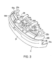
- Figs.1-6 show the first embodiment, in which Fig.1 is a perspective diagram of a front part of a vehicle; Fig.2 is a perspective diagram of a front part of a vehicle body; Fig.3 is a perspective diagram of a nose unit; Fig.4 is a exploded perspective view of a nose unit; Fig.5 is a diagram illustrating a mounting of a support member; and Fig.6 is a sectional view taken on line VI-VI of Fig.5.
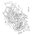
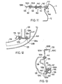
- Figs.7-13 show the second embodiment, in which Fig.7 is a diagram illustrating a relationship of a unit base and a jig for mounting a nose unit; Fig.8 is a exploded perspective view of a nose unit; Fig.9 is a diagram illustrating mounting of a nose unit to a front part of a vehicle body; Fig.10 is a diagram illustrating a front part of a vehicle body after a nose unit is mounted thereon; and Figs.11-13 are sectional views taken on lines x-x, Y-Y, Z-Z of Fig.10 respectively.
- reference numeral 1 designates a vehicle
- a nose unit 3 is mounted on the front part of the vehicle body 2.
- Front fenders 4 are provided on the both sides of the body 2
- a bonnet 5 is provided on the front top of the vehicle body 2.
- front side flames 13 are connected to lower parts of wheel aprons 12 forming right and left side walls of an engine room 11, and a wheel apron reinforcements 14 are connected to upper parts of the wheel aprons 12 so that both top and bottom closed sectional constructions extending longitudinally of the vehicle body are formed.
- a coss member 15 extending in the widthwise direction of the vehicle body is installed between the front side flames 13.
- both right and left ends of the cross member 15 are fixed to the under side of the right and left front side flames 13.
- a front end panels 18 are connected to the front end portion of the wheel aprons 12, wheel apron reinforcements 14, and the front side flames 13.
- the nose unit 3 is connected to a shroud panels 21 and a shroud upper 22 extending in the widthwise direction of the vehicle body on the upper end portion of the shroud panels 21.
- This shroud upper 22 comprises a vertical wall part 22A extending vertically, an upper wall part 22B extending rearwardly from the upper end of the vertical wall part 22A, and a rear wall part 22C extending downwardly from the rear end of the upper wall part 22B.
- a pair of vertical members 23 are hunging down from a center part in the widthwise direction of the upper wall part 22B.
- a support member 26 extending in the widthwise direction of the vehicle body and having approximate L-shaped section is provided.
- a support member 26 comprises an upper wall part 26A for supporting a condenser 24A and a lower part of a radiator 25B both are weight members 24 and a vertical wall part 26B extending downwardly from the front end of the upper wall part 26A.
- a condenser 24A and a radiator 24B are connected integrally by a member not shown in the drawings, the lower end portion of them are supported by mounting portions 26a on the upper wall part 26A of the support member 26 through a rubber mount members 27, the upper end portion of them is clamped to an upper wall part 22B (fitting hales 22A) of the shroud upper 22 by bolts (in Fig.5, only bolts 29 for one of brackets 28 are shown) through brackets 28.
- Mounting portions 23a are formed around the lower end portion of the vertical members 23, two bolts 33 from four-in-a-set bolts, which are provided to a bumper reinforcement 32 that a bumper 31 is mounted to, are fastened to a front end flange part 13a of the front side flame 13 through the mounting portions 23a. Two other bolts 34 are fastened to a mounting flange part 12a of the wheel apron 12 through the front end panel 18, passing through a lower side cut out part 21a of the shroud panel 21.
- the both ends of the bumper 31 are also connected to a mounting portion 4a of the front fender 4 of the vehicle body 2 by bolts 35 provided on the bumper 31 and bolts (not shown in the drawings) passing through a fitting hole 31a of a bumper 31.
- Both ends 22b of the upper wall parts 22B of the shroud upper 22 are clamped to both a mounting portion 4b of the top of the front fender 4 and a wheel apron reinforcement 14 by bolts (only two bolts 36 of one mounting portion 22b are shown in Fig.5).
- the support member 26 is supported on the cross member 15 (upper member 16) wherein the nose unit 3 is mounted to the vehicle body 2 and connected to a front wall part 16A and an upper wall part 16B of the upper member 16 of the cross member 15 by tightening bolts (only two bolts 41 are shown in Fig.5) through five fitting holes 26b of an upper wall part 26A of the support member 26 and the front wall part 26B.
- five nuts 42 are welded corresponding to the fitting holes 26b of the support member 26.
- Reference numeral 51 designates an intercooler, an upper part thereof is clamped to the vertical wall part 22A of the shroud upper 22 by bolts 53 through brackets 52.
- the lower end portion of the intercooler 51 is supported by brackets projecting from the bumper reinforcement 32, this is not shown in drawings.
- Reference numeral 54 designates a radiator grille positioned at front center part of a vehicle, having both right and left mounting portions 54a fitted into fitting holes of the vertical wall parts 22A of the shroud upper 22 and a mounting portion 54b at center fitted into fitting holes of a vertical member 56 of bonnet lock means 55.
- Bonnet lock means 55 is connected to a vertical wall part 22A of the shroud upper 22 by tightening bolts 57.
- Reference numerals 61A, 61B are right and left lump unit, mounting portions 61a on the upper end of each unit is clamped to the vertical wall part 22A of the shroud upper 22 by bolts 62, and a mounting portion 61b on the lower end of each unit is connected to the shroud panel 21 by bolts 63 (only bolts 62, 63 and 61b for the lump unit 61A are illustrated in the drawing).
- Reference numerals 64, 65 are harness and similar to harness for connecting electric system, the former numeral 64 is clamped the support member 26 by bolts 67 into a mounting portion 66 and the latter numeral 65 is fitted into a fitting hole of the upper wall part 22B of the shroud upper 22 through mounting portions 68.
- Reference numerals 71 designate shock absorber member for the shock at opening/closing the bonnet 5 and connected to an upper wall part 22B of the shroud upper 22.
- nose unit 3 is built first other than the vehicle body 2 which the cross member 15 is interposed between both right and left side flames 13.
- the unit base 6 having the shroud panel 21, the shroud upper 22, the vertical members 23, and the support member 26 is formed by providing the support member 26 between the lower end portion of the vertical members 23.
- the lower part of a heavyweight member 24 (the condenser 24A and the radiator 24B) is both supported by and fixed to the support member 26 and the upper end portion of the heavyweight member are supported on the shroud upper 22 through brackets 28. Then the components are mounted so as to construct the nose unit 3.
- the support member 26 is supported on the cross member 15, an implement is inserted through the space between the bumper reinforcement 32 (the bumper 31) and the cross member 15 (the support member 26), the support member 26 is clamped to the cross member 15 (nuts 42 of the upper member 16) by five bolts 41.
- the support member 26 for supporting the lower part of the heavyweight member 24 having the condenser 24A and the radiator 24B is supported by the cross member 15 and clamped to the front part of a vehicle by bolts 41 and nuts 42 (refer to Fig.6). This results in securing the supporting rigidity of the condenser 24A and the radiator 24B.
- the bumper 31 and the bumper reinforcement 32 composes a part of the nose unit by being temporarily supported by the shroud panel 21 through brackets (not shown in the drawing).
- bumper, etc. can be excluded from the nose unit and can be mounted to the front part of a vehicle later.
- the support member for supporting the heavyweight member such as a radiator is included of one member extending in the widthwise direction of the vehicle body, however, it can be included of two support members 128 having separated with a fixed distance in the widthwise direction as shown in the following second embodiment 2 (refer to Figs.17-13).
- each components are fitted to a nose unit 121 wherein a unit base 123 is put on a jig 122 for mounting a nose unit.
- the jig 122 for mounting the nose unit comprises a base part 122a extending in the widthwise direction of the vehicle body, vertical arm parts 122b, 122c extending upwardly from the both ends of the base part 122a, and arm parts 122d, 122e extending to the inboard from the upper ends of the arm parts 122d, 122e.
- On the base part 122a three engaging pins 124A, 124B, 124C are provided upwardly projecting, but moving in the vertical direction, and on the arm parts 122d, 122e, two engaging pins 124D, 124E are provided downwardly projecting, but moving in the vertical direction.
- the engaging pins 124A-124E moves vertically by cylinders (only cylinders 181D, 181E for the engaging pins 124D, 124E are shown in the drawing).
- the unit base 123 basically comprises right and left shroud panels 125, a shroud upper 126 extending in the widthwise direction of the vehicle body and fixed to the upper end of the shroud panels 125, a center steer 127 hunging down from the mid-position of the shroud upper 126 in the widthwise direction of the vehicle body, and first and second support members 128 each fixed to the lower end portion of each shroud panel 125.
- the shroud upper 126 comprises a vertical wall part 126A extending vertically, an upper wall part 126B extending rearwardly from the upper end of the vertical wall part 126A, and a rear wall part 126C extending downwardly front the rear end of the upper wall part 126B (refer to Fig.13).
- the center steer 127 extending in the vertical direction of the vehicle body is hunging down from the mid-portion of the vertical wall part A in the widthwise direction of the vehicle body.
- Each support member 128 comprises an upper wall part 128a for supporting a lower part of a radiator 129 which is a weight member, a vertical wall part 128b extending downwardly from the front end of the upper wall part 128a and is contacted to the shroud panel 125, and a support part 128c for supporting a cooler condenser 130 which is a heavyweight member and projects to the front from the lower end of the vertical wall part 128b.
- an engaging part comprising fitting holes 126a, 126b, 127a, 128d, 128d for detacheably connection with the engaging pins 124D, 124E, 124B, 124A, 124C are formed.
- the position of the nose unit 121 is determined by the relationship between the engaging pins 124D, 124E, 124B, 124A, 124C and the fitting holes 126a, 126b, 127a, 128d, 128d.
- a lower end portion of a radiator 129 and the cooler condensor 130 is supported by upper wall parts 128a of the support members 128 (fitting holes 128e) and support parts 128c (fitting holes) through rubber mounts 131A, 131B.
- the upper end portion of the radiator 129 and the cooler condenser 130 are clamped to the upper wall part 126B of the shroud upper 126 reinforced by a radiator reinforcement 133 (refer to Fig.11) and a vertical wall part 126A by bolts 134A, 134B through brackets 132A, 132B respectively.
- reference numeral 157 designates a nut screwed on the bolt 134A which is already welded on the under side of an upper wall part 126B of the shroud upper 126 through the radiator reinforcement 133.
- Mounting portions 125a are formed around the lower end portion of the shroud panels 125 so that two inner bolts 137A out of four-in-a-set bolts disposed on the bumper reinforcement 136, which a bumper face 135 is mounted to, are fixed to the mounting portions 125a as a temporarily mounting for forming a unit by using a nut 142.
- the other outer two bolts 137B are fixed to a front flange part 139a of a flame outer 139A of a front flame 139 through side part 138a of a cross member 138 when mounting a nose unit 121 to a front part of a vehicle so that the bumper reinforcement 136 is connected to the vehicle body 2 directly (refer to Fig.12).
- Both ends of the upper wall part 126B of the shroud upper 126 are clamped to a shroud bracket 141 by bolts 140.
- a base part of this shroud bracket 141 is clamped between the wheel apron reinforcement 14 and the front fender 4 by a bolt 143 and a nut 144.
- the support member 128 is supported on the cross member 138 wherein the nose unit 121 is installed in the front part of the vehicle body 2 and fixed to a front wall part and an upper wall part of an upper member 138A of the cross member 138 by bolts 147, 148 and nuts 145, 146 through seven fitting holes of an upper wall part 128a and a front wall part 128b of the support member 128 (refer to Fig.13).
- Reference numeral 151 designates a cooler receiver, the side part thereof is clamped to the center steer 127 by bolts 153 through bracket 152.
- a joint metal fitting 155 of a horse member 154 from a cooler receiver 151 is connected to a joint metal fitting of a horse member 155A of the cooler condenser 130.
- Reference numeral 161 designates bonnet lock means clamped to a vertical wall part 126A of the shroud upper 126 by bolts 162 through the center steer 127.
- Reference numeral 163 designates a power steering pipe clamped to a center steer 127 and one of the shroud panels 125 through a mounting implement 164 and bolts 165.
- Reference numerals 166 designate horn members fixed to the center steer 127 by a bolt 167.
- Right and left lump units 172 comprising a radiator grille 171, a head lump 172A, and a front combination lump 172B, those positioned front center part of the vehicle, are mounted to the nose unit and the vehicle body after the nose unit 121 is mounted to the vehicle body as shown in Fig.10, this step differs from the first embodiment.
- the radiator grille 171 comprises engaging parts 171a, 171b, 171c, having right and left side engaging parts 171a, 171c connected detacheably to a vertical wall part 126A (fitting in a fitting hole) of the shroud upper 126 and a center engaging part 171b connected detacheably to a vertical wall part 126A (fitting in a fitting hole) of the shroud upper 126 through bonnet lock means 161.
- a lump unit 172 mounting portions 172a, 172b on the head lump 172A side are fixed to a side end portion of the shroud panel 125 and un upper wall part 126B (a fitting hole) of the shroud upper 126 by bolts 182, 183 respectively, and an engaging portion 172c on the front combination lump 172B side is fitted in to an engaging portion 184 of the wheel apron.
- each components are mounted to the bose wherein the unit base 123 is supported by the jig 122 for mounting the nose unit and positioned by the relationship between the engaging pins 124A-124E and the fitting holes 126a, 126b 127a, 128d, 128d (refer to Fig.8).
- the nose unit 121 is put on a truck 173 with the jig 122 and mounted to the front part of the vehicle body 2 moving on an assembling line S (a main line).
- an assembling line S a main line.
- engaging projecting parts 174a of a deformation preventing jig 174 for preventing the deformation is detacheably engaged with engaging portions 2A of both right and left sides of the vehicle body 2, engaging portions 2A and the deformation preventing tool 174 can be excluded since the cross member 138 has an effect for preventing a deformation of the front part of a vehicle.
- center steer 127 and the support member 128 are clamped to the cross member 138 by screwing a nut 146 on the bolt 147 through fastener 175, 176 by using a bolt 148 and a nut 145.
- the bumper reinforcement 136 is fixed to a side part 138a of the cross member 138 by screwing a nut 149 on a bolt 137B by a fastener 177.
- the shroud upper 126 is fixed to the shroud bracket 141 by screwing nuts 150 on bolts 140 by a fastener 178.
- the radiator grille 171 and the lump unit 172 are installed after thus the nose unit 121 is mounted to the front part of the vehicle body 2 (refer to Fig.10).
Landscapes
- Engineering & Computer Science (AREA)
- Chemical & Material Sciences (AREA)
- Combustion & Propulsion (AREA)
- Transportation (AREA)
- Mechanical Engineering (AREA)
- Body Structure For Vehicles (AREA)
- Automatic Assembly (AREA)
- Automobile Manufacture Line, Endless Track Vehicle, Trailer (AREA)
Applications Claiming Priority (2)
| Application Number | Priority Date | Filing Date | Title |
|---|---|---|---|
| JP333139/89 | 1989-12-21 | ||
| JP33313989 | 1989-12-21 |
Publications (3)
| Publication Number | Publication Date |
|---|---|
| EP0437781A2 true EP0437781A2 (fr) | 1991-07-24 |
| EP0437781A3 EP0437781A3 (en) | 1991-07-31 |
| EP0437781B1 EP0437781B1 (fr) | 1995-10-11 |
Family
ID=18262728
Family Applications (1)
| Application Number | Title | Priority Date | Filing Date |
|---|---|---|---|
| EP90124793A Expired - Lifetime EP0437781B1 (fr) | 1989-12-21 | 1990-12-19 | Structure de la partie avant pour un véhicule |
Country Status (5)
| Country | Link |
|---|---|
| US (1) | US5123695A (fr) |
| EP (1) | EP0437781B1 (fr) |
| JP (1) | JP2933702B2 (fr) |
| KR (1) | KR940002084B1 (fr) |
| DE (1) | DE69022968T2 (fr) |
Cited By (11)
| Publication number | Priority date | Publication date | Assignee | Title |
|---|---|---|---|---|
| FR2775649A1 (fr) * | 1998-03-05 | 1999-09-10 | Mc Micro Compact Car Ag | Procede et dispositif d'assemblage d'un module arriere et d'un module essieu avant d'un vehicule automobile |
| WO1999054187A1 (fr) * | 1998-04-21 | 1999-10-28 | Textron Automotive Uk | Module de vehicule |
| US6517146B1 (en) | 1999-11-15 | 2003-02-11 | Compagnie Plastic Omnium | Attachment of front quadrant to crossmember |
| EP1279587A3 (fr) * | 2001-07-25 | 2003-04-02 | Nissan Motor Company, Limited | Dispositif et méthode pour fixer un élément au chassis |
| WO2006120359A1 (fr) * | 2005-05-12 | 2006-11-16 | Compagnie Plastic Omnium | Procede de conformation d’une peau de pare-chocs autour de blocs optiques, renfort pour peau de pare-chocs et bloc avant de vehicule automobile |
| WO2009071244A1 (fr) * | 2007-12-06 | 2009-06-11 | Bayerische Motoren Werke Aktiengesellschaft | Carrosserie de véhicule équipée d'un élément de carrosserie |
| FR2928895A1 (fr) * | 2008-03-21 | 2009-09-25 | Peugeot Citroen Automobiles Sa | Facade avant pour vehicule notamment automobile |
| DE102009033945A1 (de) * | 2009-07-13 | 2011-02-10 | Decoma (Germany) Gmbh | Verfahren zur Montage eines Gesamtsystems für ein Fahrzeug |
| US20230060018A1 (en) * | 2020-02-18 | 2023-02-23 | Bayerische Motoren Werke Aktiengesellschaft | Support Device of a Front End Module, and Vehicle Comprising a Support Device |
| WO2024078822A1 (fr) * | 2022-10-14 | 2024-04-18 | Bayerische Motoren Werke Aktiengesellschaft | Structure frontale pour un véhicule automobile |
| CZ310303B6 (cs) * | 2020-12-31 | 2025-02-05 | ŠKODA AUTO a.s. | Přípravek pro slícování částí karoserie motorového vozidla |
Families Citing this family (55)
| Publication number | Priority date | Publication date | Assignee | Title |
|---|---|---|---|---|
| JP2565377Y2 (ja) * | 1991-09-06 | 1998-03-18 | マツダ株式会社 | 自動車の前部車体構造 |
| JPH05170135A (ja) * | 1991-12-18 | 1993-07-09 | Mazda Motor Corp | 自動車の前部車体構造 |
| DE4437083C2 (de) * | 1993-10-25 | 1996-10-17 | Fuji Heavy Ind Ltd | Modulträgerstruktur |
| JPH07205666A (ja) * | 1994-01-17 | 1995-08-08 | Kubota Corp | 農作業車のボンネット |
| US5499690A (en) * | 1994-02-03 | 1996-03-19 | Paccar Inc. | Integral hood, radiator and bumper support apparatus |
| GB2319994B (en) * | 1996-12-04 | 2001-05-23 | Massey Ferguson Ltd | Vehicle body panel assembly |
| JPH10264855A (ja) | 1997-03-26 | 1998-10-06 | Aisin Seiki Co Ltd | 車両フロントエンドモジュール構造 |
| ATE240864T1 (de) * | 1997-10-24 | 2003-06-15 | Decoma Int Inc | Endplattenanordnung zur befestigung an einem fahrzeug und verfahren zu deren herstellung |
| JPH11165653A (ja) * | 1997-11-30 | 1999-06-22 | Isuzu Motors Ltd | フレーム付ボディ車のバンパ取付構造 |
| US6282769B1 (en) | 1998-07-15 | 2001-09-04 | Cosma International Inc. | Motor vehicle end module assembly |
| FR2784644B1 (fr) * | 1998-10-16 | 2000-11-24 | Inoplast Sa | Procede de fabrication d'une face avant de vehicule automobile et face avant apte a etre fabriquee par ce procede |
| US6386624B1 (en) * | 1998-10-29 | 2002-05-14 | Plastech | Front end assembly for an automotive vehicle |
| FR2787410B1 (fr) * | 1998-12-21 | 2001-03-09 | Ecia Equip Composants Ind Auto | Face avant et agencement de cette face avant dans un vehicule automobile |
| US6502653B1 (en) | 1999-10-13 | 2003-01-07 | Ford Global Technologies, Inc. | Multi-functional radiator support assembly |
| US6357821B1 (en) * | 1999-10-13 | 2002-03-19 | Ford Global Technologies, Inc. | Lamp can and radiator support assembly |
| US6679545B1 (en) * | 1999-10-13 | 2004-01-20 | Ford Global Technologies, Llc | Multi-functional radiator support assembly |
| JP4461563B2 (ja) * | 1999-10-20 | 2010-05-12 | 株式会社デンソー | 車両のフロントエンド構造 |
| JP2001121941A (ja) * | 1999-10-28 | 2001-05-08 | Denso Corp | 熱交換器の車両搭載構造 |
| FR2801031B1 (fr) * | 1999-11-15 | 2002-02-15 | Plastic Omnium Cie | Face avant technique de vehicule automobile avec mise en reference sur l'aile du vehicule |
| US6883589B2 (en) * | 2000-01-31 | 2005-04-26 | Denso Corporation | Front end structure |
| JP4320899B2 (ja) * | 2000-02-03 | 2009-08-26 | 株式会社デンソー | フロントエンドパネル |
| JP4320907B2 (ja) * | 2000-04-03 | 2009-08-26 | 株式会社デンソー | 車両のフロントエンド構造 |
| US6648089B1 (en) * | 2000-08-07 | 2003-11-18 | International Truck Intellectual Property Company, Llc | Cooling module mounting system and assembly process |
| DE60105948T3 (de) * | 2000-11-29 | 2009-07-09 | Calsonic Kansei Corp. | Trägerstruktur für Kfz-Kühleranordnung |
| EP1213207B2 (fr) * | 2000-12-07 | 2014-11-26 | Calsonic Kansei Corporation | Structure de support pour bloc de radiateur d'un véhicule |
| JP3912479B2 (ja) * | 2001-01-22 | 2007-05-09 | スズキ株式会社 | フロントグリル構造 |
| FR2820706B1 (fr) * | 2001-02-15 | 2003-05-16 | Faurecia Ind | Ensemble de bloc avant de vehicule automobile comportant un dispositif ameliore de fixation des composants, et vehicule equipe d'un tel ensemble |
| JP3747811B2 (ja) * | 2001-06-20 | 2006-02-22 | 日産自動車株式会社 | フロントエンドモジュールの組み付け方法 |
| DE60212394T2 (de) * | 2001-07-18 | 2007-06-14 | Decoma International Inc., Concord | Komponententräger-verkleidungseinheit in verbundbauweise für ein kraftfahrzeug |
| JP4034057B2 (ja) * | 2001-09-28 | 2008-01-16 | カルソニックカンセイ株式会社 | 自動車の車体前部構造およびそれに使用されるラジエータコアサポートメンバ |
| KR100428338B1 (ko) * | 2001-10-16 | 2004-04-28 | 현대자동차주식회사 | 차량의 볼스터 어셈블리용 지그장치 |
| CA2470625C (fr) | 2001-12-17 | 2010-12-14 | Decoma International Inc. | Ensemble calandre avec panneau d'integration de composants |
| JP3666658B2 (ja) * | 2002-02-14 | 2005-06-29 | マツダ株式会社 | 車両のラジエータモジュールの組付け方法及びその組付け装置 |
| DE10250334A1 (de) * | 2002-10-29 | 2004-05-19 | Modine Manufacturing Co., Racine | Wärmetauscheranordnung für Kraftfahrzeuge |
| FR2851221B1 (fr) * | 2003-02-18 | 2005-08-05 | Plastic Omnium Cie | Face avant technique de vehicule automobile, comportant une traverse superieure renforcee |
| JP2005035436A (ja) * | 2003-07-16 | 2005-02-10 | Calsonic Kansei Corp | 自動車の車体前部構造 |
| US6948769B2 (en) * | 2003-12-22 | 2005-09-27 | Nissan Technical Center North America, Inc. | Vehicle front end structure |
| JP2006103643A (ja) * | 2004-10-08 | 2006-04-20 | Calsonic Kansei Corp | ラジエータコアサポート構造 |
| US7416038B2 (en) * | 2005-02-04 | 2008-08-26 | International Truck Intellectual Property Company, Llc | Tubular hinge bar |
| US20060207815A1 (en) * | 2005-03-17 | 2006-09-21 | Nissan Technical Center North America, Inc. | Condenser arrangement |
| FR2899558B1 (fr) * | 2006-04-06 | 2008-05-16 | Renault Sas | Procede de montage sur un vehicule automobile d'elements de soubassement |
| FR2901213B1 (fr) * | 2006-05-19 | 2008-09-05 | Plastic Omnium Cie | Agencement d'un radiateur, d'un absorbeur et d'une poutre de chocs sur un vehicule automobile |
| JP4165588B2 (ja) * | 2006-08-04 | 2008-10-15 | トヨタ自動車株式会社 | 車両のカバー |
| JP5024653B2 (ja) * | 2006-10-02 | 2012-09-12 | スズキ株式会社 | フロントバンパ |
| FR2914618B1 (fr) * | 2007-04-03 | 2009-09-18 | Renault Sas | Procede de montage d'un element de soubassement transversal et d'une face avant technique |
| US20080258449A1 (en) * | 2007-04-17 | 2008-10-23 | Ronald Allen Wehner | Retention arrangement for vehicle front-end module |
| US7988225B2 (en) * | 2008-03-31 | 2011-08-02 | Honda Motor Co., Ltd. | Vehicle front fascia support member |
| KR100925926B1 (ko) * | 2008-05-29 | 2009-11-09 | 현대자동차주식회사 | 자동차 프론트엔드부의 듀얼 에어덕트 |
| FR2936771B1 (fr) * | 2008-10-03 | 2011-06-10 | Renault Sas | Agencement pour le montage d'une face avant technique de vehicule. |
| WO2011152125A1 (fr) * | 2010-05-31 | 2011-12-08 | スズキ株式会社 | Structure pour partie frontale de véhicule |
| JP5777101B2 (ja) * | 2011-08-31 | 2015-09-09 | ダイハツ工業株式会社 | フロントエンドモジュールの組付方法及び搬送台車 |
| FR2981887B1 (fr) * | 2011-11-02 | 2015-04-17 | Renault Sas | Guide d'air structurel et modulaire a fonction de face avant technique de moteur de vehicule automobile et vehicule ainsi equipe. |
| JP5968853B2 (ja) * | 2013-10-25 | 2016-08-10 | 豊田鉄工株式会社 | ラジエータコアサポート |
| US9440527B1 (en) * | 2015-06-26 | 2016-09-13 | Kawasaki Jukogyo Kabushiki Kaisha | Utility vehicle |
| JP7014092B2 (ja) * | 2018-08-07 | 2022-02-01 | トヨタ自動車株式会社 | 車両前部構造 |
Family Cites Families (9)
| Publication number | Priority date | Publication date | Assignee | Title |
|---|---|---|---|---|
| US1874400A (en) * | 1929-12-02 | 1932-08-30 | Harrison Radiator Corp | Radiator structure |
| US2715448A (en) * | 1952-01-03 | 1955-08-16 | Chrysler Corp | Front sheet metal construction for automotive vehicles |
| JPS58152673A (ja) * | 1982-03-08 | 1983-09-10 | Mazda Motor Corp | 自動車の前部車体構造 |
| DE3315646C2 (de) * | 1983-04-29 | 1989-06-08 | Adam Opel AG, 6090 Rüsselsheim | Vormontierte Baueinheit für den Spritzwand-Bereich von Kraftfahrzeugen, insbesondere Personenkraftwagen, und Verfahren zum Einbau einer solchen vormontierten Baueinheit |
| IT8453877V0 (it) * | 1984-10-01 | 1984-10-01 | Fiat Auto Spa | Autoveicolo comprendente un sotto gruppo preassemblato formato dal motopropulsore e da una serie di componenti degli impianti di bordo |
| JPS63103773A (ja) * | 1986-10-21 | 1988-05-09 | Nissan Motor Co Ltd | 車体組立方法 |
| JPH07115655B2 (ja) * | 1986-10-22 | 1995-12-13 | 日産自動車株式会社 | 自動車の車体前部組立方法 |
| JPS63110075A (ja) * | 1986-10-27 | 1988-05-14 | Nissan Motor Co Ltd | エンジンコンパ−トメントの組立方法 |
| IT1196845B (it) * | 1986-12-16 | 1988-11-25 | Fiat Auto Spa | Modulo anteriore di scocca per autovetture sottinsieme modulare anteriore di autovetture utilizzante tale modulo anteriore e procedimento di assemblaggio di un autovettura mediante tale sottinsieme modulare |
-
1990
- 1990-11-06 JP JP2301892A patent/JP2933702B2/ja not_active Expired - Fee Related
- 1990-12-19 EP EP90124793A patent/EP0437781B1/fr not_active Expired - Lifetime
- 1990-12-19 DE DE69022968T patent/DE69022968T2/de not_active Expired - Fee Related
- 1990-12-19 US US07/629,789 patent/US5123695A/en not_active Expired - Lifetime
- 1990-12-21 KR KR1019900021695A patent/KR940002084B1/ko not_active Expired - Fee Related
Cited By (15)
| Publication number | Priority date | Publication date | Assignee | Title |
|---|---|---|---|---|
| FR2775649A1 (fr) * | 1998-03-05 | 1999-09-10 | Mc Micro Compact Car Ag | Procede et dispositif d'assemblage d'un module arriere et d'un module essieu avant d'un vehicule automobile |
| WO1999054187A1 (fr) * | 1998-04-21 | 1999-10-28 | Textron Automotive Uk | Module de vehicule |
| US6517146B1 (en) | 1999-11-15 | 2003-02-11 | Compagnie Plastic Omnium | Attachment of front quadrant to crossmember |
| EP1279587A3 (fr) * | 2001-07-25 | 2003-04-02 | Nissan Motor Company, Limited | Dispositif et méthode pour fixer un élément au chassis |
| US6895647B2 (en) | 2001-07-25 | 2005-05-24 | Nissan Motor Co., Ltd. | Device and method for mounting part to base structure |
| FR2885587A1 (fr) * | 2005-05-12 | 2006-11-17 | Plastic Omnium Cie | Procede de conformation d'une peau de pare-chocs autour de blocs optiques, renfort pour peau de pare-chocs et bloc avant de vehicule automobile |
| WO2006120359A1 (fr) * | 2005-05-12 | 2006-11-16 | Compagnie Plastic Omnium | Procede de conformation d’une peau de pare-chocs autour de blocs optiques, renfort pour peau de pare-chocs et bloc avant de vehicule automobile |
| US7914070B2 (en) | 2005-05-12 | 2011-03-29 | Compagnie Plastic Omnium | Method for fitting a bumper shell around light units stay for a bumper shell and headlight unit for motor vehicles |
| WO2009071244A1 (fr) * | 2007-12-06 | 2009-06-11 | Bayerische Motoren Werke Aktiengesellschaft | Carrosserie de véhicule équipée d'un élément de carrosserie |
| FR2928895A1 (fr) * | 2008-03-21 | 2009-09-25 | Peugeot Citroen Automobiles Sa | Facade avant pour vehicule notamment automobile |
| DE102009033945A1 (de) * | 2009-07-13 | 2011-02-10 | Decoma (Germany) Gmbh | Verfahren zur Montage eines Gesamtsystems für ein Fahrzeug |
| US20230060018A1 (en) * | 2020-02-18 | 2023-02-23 | Bayerische Motoren Werke Aktiengesellschaft | Support Device of a Front End Module, and Vehicle Comprising a Support Device |
| US12202547B2 (en) * | 2020-02-18 | 2025-01-21 | Bayerische Motoren Werke Aktiengesellschaft | Support device of a front end module, and vehicle comprising a support device |
| CZ310303B6 (cs) * | 2020-12-31 | 2025-02-05 | ŠKODA AUTO a.s. | Přípravek pro slícování částí karoserie motorového vozidla |
| WO2024078822A1 (fr) * | 2022-10-14 | 2024-04-18 | Bayerische Motoren Werke Aktiengesellschaft | Structure frontale pour un véhicule automobile |
Also Published As
| Publication number | Publication date |
|---|---|
| DE69022968D1 (de) | 1995-11-16 |
| JP2933702B2 (ja) | 1999-08-16 |
| EP0437781A3 (en) | 1991-07-31 |
| KR910011578A (ko) | 1991-08-07 |
| EP0437781B1 (fr) | 1995-10-11 |
| KR940002084B1 (ko) | 1994-03-17 |
| JPH03227781A (ja) | 1991-10-08 |
| US5123695A (en) | 1992-06-23 |
| DE69022968T2 (de) | 1996-05-30 |
Similar Documents
| Publication | Publication Date | Title |
|---|---|---|
| EP0437781B1 (fr) | Structure de la partie avant pour un véhicule | |
| US5358304A (en) | Front body structure of a vehicle and assembling method | |
| AU762588C (en) | Reinforcement of instrument panel | |
| EP0449241B1 (fr) | Structure de la partie avant pour un véhicule automobile | |
| EP0437780B2 (fr) | Structure de la partie avant pour un véhicule | |
| JP2907502B2 (ja) | 車両の前部車体の組立方法 | |
| JPS5824288B2 (ja) | スライデイングル−フ装着車の車体ル−フ構造およびその組付方法 | |
| JP2898339B2 (ja) | 自動車の前部車体構造及び車体組立方法 | |
| KR20230055100A (ko) | 차량의 언더 프로텍터 체결 구조 | |
| JPH08258745A (ja) | 自動車の車体フロント構造 | |
| JP3374581B2 (ja) | 自動車の車体フロント構造 | |
| JP2549519Y2 (ja) | 自動車の車体構造 | |
| JPH03213472A (ja) | 自動車の前部車体構造及びその組立方法 | |
| JP2889010B2 (ja) | 車両の組付方法 | |
| JPH02293277A (ja) | 自動車の前部車体構造 | |
| JP2937458B2 (ja) | 自動車の前部車体構造およびその組立方法 | |
| JP2848666B2 (ja) | 自動車の前部車体構造及び車体組立方法 | |
| JPH0245064Y2 (fr) | ||
| JPH07112778B2 (ja) | 自動車のドア構造 | |
| KR100414649B1 (ko) | 자동차의 필러 | |
| JP2933659B2 (ja) | 自動車の前部車体組立方法 | |
| US20250333116A1 (en) | Vehicle body | |
| JP2548009Y2 (ja) | 自動車のカウル部の構造 | |
| JPH04197880A (ja) | 車両の前部車体構造 | |
| JP2565503Y2 (ja) | ハイマウントストップランプの取付構造 |
Legal Events
| Date | Code | Title | Description |
|---|---|---|---|
| PUAI | Public reference made under article 153(3) epc to a published international application that has entered the european phase |
Free format text: ORIGINAL CODE: 0009012 |
|
| PUAL | Search report despatched |
Free format text: ORIGINAL CODE: 0009013 |
|
| AK | Designated contracting states |
Kind code of ref document: A2 Designated state(s): DE FR GB |
|
| AK | Designated contracting states |
Kind code of ref document: A3 Designated state(s): DE FR GB |
|
| 17P | Request for examination filed |
Effective date: 19911031 |
|
| 17Q | First examination report despatched |
Effective date: 19930602 |
|
| GRAA | (expected) grant |
Free format text: ORIGINAL CODE: 0009210 |
|
| AK | Designated contracting states |
Kind code of ref document: B1 Designated state(s): DE FR GB |
|
| REF | Corresponds to: |
Ref document number: 69022968 Country of ref document: DE Date of ref document: 19951116 |
|
| ET | Fr: translation filed | ||
| PLBE | No opposition filed within time limit |
Free format text: ORIGINAL CODE: 0009261 |
|
| STAA | Information on the status of an ep patent application or granted ep patent |
Free format text: STATUS: NO OPPOSITION FILED WITHIN TIME LIMIT |
|
| 26N | No opposition filed | ||
| PGFP | Annual fee paid to national office [announced via postgrant information from national office to epo] |
Ref country code: FR Payment date: 20001212 Year of fee payment: 11 |
|
| PGFP | Annual fee paid to national office [announced via postgrant information from national office to epo] |
Ref country code: GB Payment date: 20001213 Year of fee payment: 11 |
|
| PG25 | Lapsed in a contracting state [announced via postgrant information from national office to epo] |
Ref country code: GB Free format text: LAPSE BECAUSE OF NON-PAYMENT OF DUE FEES Effective date: 20011219 |
|
| REG | Reference to a national code |
Ref country code: GB Ref legal event code: IF02 |
|
| GBPC | Gb: european patent ceased through non-payment of renewal fee |
Effective date: 20011219 |
|
| PG25 | Lapsed in a contracting state [announced via postgrant information from national office to epo] |
Ref country code: FR Free format text: LAPSE BECAUSE OF NON-PAYMENT OF DUE FEES Effective date: 20020830 |
|
| REG | Reference to a national code |
Ref country code: FR Ref legal event code: ST |
|
| PGFP | Annual fee paid to national office [announced via postgrant information from national office to epo] |
Ref country code: DE Payment date: 20061214 Year of fee payment: 17 |
|
| PG25 | Lapsed in a contracting state [announced via postgrant information from national office to epo] |
Ref country code: DE Free format text: LAPSE BECAUSE OF NON-PAYMENT OF DUE FEES Effective date: 20080701 |