EP0437890A1 - Méthode de production de matériaux multicomposants - Google Patents
Méthode de production de matériaux multicomposants Download PDFInfo
- Publication number
- EP0437890A1 EP0437890A1 EP90203468A EP90203468A EP0437890A1 EP 0437890 A1 EP0437890 A1 EP 0437890A1 EP 90203468 A EP90203468 A EP 90203468A EP 90203468 A EP90203468 A EP 90203468A EP 0437890 A1 EP0437890 A1 EP 0437890A1
- Authority
- EP
- European Patent Office
- Prior art keywords
- target
- ultrafine particles
- particles
- substrate
- laser beam
- Prior art date
- Legal status (The legal status is an assumption and is not a legal conclusion. Google has not performed a legal analysis and makes no representation as to the accuracy of the status listed.)
- Withdrawn
Links
- 239000000463 material Substances 0.000 title claims abstract description 49
- 238000004519 manufacturing process Methods 0.000 title claims description 14
- 239000011882 ultra-fine particle Substances 0.000 claims abstract description 67
- 239000000758 substrate Substances 0.000 claims abstract description 45
- 238000000151 deposition Methods 0.000 claims abstract description 15
- 230000008021 deposition Effects 0.000 claims abstract description 15
- 238000001182 laser chemical vapour deposition Methods 0.000 claims abstract description 3
- 239000002245 particle Substances 0.000 claims description 62
- 239000007789 gas Substances 0.000 claims description 53
- 238000000034 method Methods 0.000 claims description 40
- 238000000576 coating method Methods 0.000 claims description 16
- 238000001704 evaporation Methods 0.000 claims description 15
- 230000008569 process Effects 0.000 claims description 14
- 239000011248 coating agent Substances 0.000 claims description 13
- 230000008020 evaporation Effects 0.000 claims description 12
- 238000010438 heat treatment Methods 0.000 claims description 12
- PNEYBMLMFCGWSK-UHFFFAOYSA-N aluminium oxide Inorganic materials [O-2].[O-2].[O-2].[Al+3].[Al+3] PNEYBMLMFCGWSK-UHFFFAOYSA-N 0.000 claims description 10
- 229910052593 corundum Inorganic materials 0.000 claims description 10
- HYXGAEYDKFCVMU-UHFFFAOYSA-N scandium(III) oxide Inorganic materials O=[Sc]O[Sc]=O HYXGAEYDKFCVMU-UHFFFAOYSA-N 0.000 claims description 10
- 229910001845 yogo sapphire Inorganic materials 0.000 claims description 10
- 238000009826 distribution Methods 0.000 claims description 7
- 239000013077 target material Substances 0.000 claims description 6
- WFKWXMTUELFFGS-UHFFFAOYSA-N tungsten Chemical group [W] WFKWXMTUELFFGS-UHFFFAOYSA-N 0.000 claims description 6
- 238000007711 solidification Methods 0.000 claims description 5
- 230000008023 solidification Effects 0.000 claims description 5
- 229910052721 tungsten Inorganic materials 0.000 claims description 5
- 239000010937 tungsten Substances 0.000 claims description 5
- 239000011261 inert gas Substances 0.000 claims description 4
- 239000011343 solid material Substances 0.000 claims description 4
- 239000012159 carrier gas Substances 0.000 claims description 3
- 239000007787 solid Substances 0.000 claims description 3
- 239000012212 insulator Substances 0.000 claims description 2
- 239000002344 surface layer Substances 0.000 claims description 2
- 230000032258 transport Effects 0.000 description 19
- 239000010410 layer Substances 0.000 description 13
- 239000012071 phase Substances 0.000 description 10
- 229910052751 metal Inorganic materials 0.000 description 9
- 239000002184 metal Substances 0.000 description 9
- 230000015572 biosynthetic process Effects 0.000 description 8
- 238000001564 chemical vapour infiltration Methods 0.000 description 8
- 238000001514 detection method Methods 0.000 description 6
- 239000000203 mixture Substances 0.000 description 6
- 238000010521 absorption reaction Methods 0.000 description 5
- 150000002739 metals Chemical class 0.000 description 5
- 230000005855 radiation Effects 0.000 description 5
- SBIBMFFZSBJNJF-UHFFFAOYSA-N selenium;zinc Chemical compound [Se]=[Zn] SBIBMFFZSBJNJF-UHFFFAOYSA-N 0.000 description 5
- VYPSYNLAJGMNEJ-UHFFFAOYSA-N Silicium dioxide Chemical compound O=[Si]=O VYPSYNLAJGMNEJ-UHFFFAOYSA-N 0.000 description 4
- 230000008901 benefit Effects 0.000 description 4
- 238000000926 separation method Methods 0.000 description 4
- 238000012546 transfer Methods 0.000 description 4
- 230000009471 action Effects 0.000 description 3
- 239000000919 ceramic Substances 0.000 description 3
- 230000008859 change Effects 0.000 description 3
- 238000001816 cooling Methods 0.000 description 3
- 238000010894 electron beam technology Methods 0.000 description 3
- 230000008018 melting Effects 0.000 description 3
- 238000002844 melting Methods 0.000 description 3
- 239000011148 porous material Substances 0.000 description 3
- 239000000843 powder Substances 0.000 description 3
- 238000002230 thermal chemical vapour deposition Methods 0.000 description 3
- XKRFYHLGVUSROY-UHFFFAOYSA-N Argon Chemical compound [Ar] XKRFYHLGVUSROY-UHFFFAOYSA-N 0.000 description 2
- IJGRMHOSHXDMSA-UHFFFAOYSA-N Atomic nitrogen Chemical compound N#N IJGRMHOSHXDMSA-UHFFFAOYSA-N 0.000 description 2
- ATUOYWHBWRKTHZ-UHFFFAOYSA-N Propane Chemical compound CCC ATUOYWHBWRKTHZ-UHFFFAOYSA-N 0.000 description 2
- 229910052581 Si3N4 Inorganic materials 0.000 description 2
- QVGXLLKOCUKJST-UHFFFAOYSA-N atomic oxygen Chemical compound [O] QVGXLLKOCUKJST-UHFFFAOYSA-N 0.000 description 2
- QVQLCTNNEUAWMS-UHFFFAOYSA-N barium oxide Inorganic materials [Ba]=O QVQLCTNNEUAWMS-UHFFFAOYSA-N 0.000 description 2
- 239000003054 catalyst Substances 0.000 description 2
- 229910052681 coesite Inorganic materials 0.000 description 2
- 150000001875 compounds Chemical class 0.000 description 2
- 238000009833 condensation Methods 0.000 description 2
- 229910052906 cristobalite Inorganic materials 0.000 description 2
- 230000001419 dependent effect Effects 0.000 description 2
- 238000009792 diffusion process Methods 0.000 description 2
- 230000005684 electric field Effects 0.000 description 2
- 238000005516 engineering process Methods 0.000 description 2
- 238000011010 flushing procedure Methods 0.000 description 2
- 230000001939 inductive effect Effects 0.000 description 2
- 230000001678 irradiating effect Effects 0.000 description 2
- 239000011159 matrix material Substances 0.000 description 2
- VNWKTOKETHGBQD-UHFFFAOYSA-N methane Chemical compound C VNWKTOKETHGBQD-UHFFFAOYSA-N 0.000 description 2
- 230000001590 oxidative effect Effects 0.000 description 2
- 239000001301 oxygen Substances 0.000 description 2
- 229910052760 oxygen Inorganic materials 0.000 description 2
- 238000009304 pastoral farming Methods 0.000 description 2
- 238000001556 precipitation Methods 0.000 description 2
- 238000010926 purge Methods 0.000 description 2
- 230000009467 reduction Effects 0.000 description 2
- 238000007789 sealing Methods 0.000 description 2
- 239000000377 silicon dioxide Substances 0.000 description 2
- 235000012239 silicon dioxide Nutrition 0.000 description 2
- 229910052682 stishovite Inorganic materials 0.000 description 2
- 229910052905 tridymite Inorganic materials 0.000 description 2
- 239000012808 vapor phase Substances 0.000 description 2
- 239000004338 Dichlorodifluoromethane Substances 0.000 description 1
- RTAQQCXQSZGOHL-UHFFFAOYSA-N Titanium Chemical compound [Ti] RTAQQCXQSZGOHL-UHFFFAOYSA-N 0.000 description 1
- 238000002679 ablation Methods 0.000 description 1
- 230000002159 abnormal effect Effects 0.000 description 1
- 238000002835 absorbance Methods 0.000 description 1
- 239000006096 absorbing agent Substances 0.000 description 1
- 239000002253 acid Substances 0.000 description 1
- 239000000853 adhesive Substances 0.000 description 1
- 230000001070 adhesive effect Effects 0.000 description 1
- 239000000443 aerosol Substances 0.000 description 1
- 238000005054 agglomeration Methods 0.000 description 1
- 230000002776 aggregation Effects 0.000 description 1
- 239000003513 alkali Substances 0.000 description 1
- 229910052786 argon Inorganic materials 0.000 description 1
- 238000000149 argon plasma sintering Methods 0.000 description 1
- 230000033228 biological regulation Effects 0.000 description 1
- 238000007664 blowing Methods 0.000 description 1
- 238000009835 boiling Methods 0.000 description 1
- 238000006243 chemical reaction Methods 0.000 description 1
- 239000007795 chemical reaction product Substances 0.000 description 1
- 230000005494 condensation Effects 0.000 description 1
- 239000000470 constituent Substances 0.000 description 1
- 238000010924 continuous production Methods 0.000 description 1
- 230000003247 decreasing effect Effects 0.000 description 1
- 238000005137 deposition process Methods 0.000 description 1
- PXBRQCKWGAHEHS-UHFFFAOYSA-N dichlorodifluoromethane Chemical compound FC(F)(Cl)Cl PXBRQCKWGAHEHS-UHFFFAOYSA-N 0.000 description 1
- 235000019404 dichlorodifluoromethane Nutrition 0.000 description 1
- 238000006073 displacement reaction Methods 0.000 description 1
- 239000003814 drug Substances 0.000 description 1
- 239000000975 dye Substances 0.000 description 1
- 230000000694 effects Effects 0.000 description 1
- 238000005530 etching Methods 0.000 description 1
- 230000005281 excited state Effects 0.000 description 1
- 238000005188 flotation Methods 0.000 description 1
- 238000005194 fractionation Methods 0.000 description 1
- 239000003779 heat-resistant material Substances 0.000 description 1
- 238000005470 impregnation Methods 0.000 description 1
- 238000001764 infiltration Methods 0.000 description 1
- 230000008595 infiltration Effects 0.000 description 1
- 238000010884 ion-beam technique Methods 0.000 description 1
- 239000007788 liquid Substances 0.000 description 1
- 229910001004 magnetic alloy Inorganic materials 0.000 description 1
- 230000005499 meniscus Effects 0.000 description 1
- 150000001247 metal acetylides Chemical class 0.000 description 1
- 238000005459 micromachining Methods 0.000 description 1
- 150000004767 nitrides Chemical class 0.000 description 1
- 229910052757 nitrogen Inorganic materials 0.000 description 1
- 230000003287 optical effect Effects 0.000 description 1
- 230000035515 penetration Effects 0.000 description 1
- 239000000049 pigment Substances 0.000 description 1
- 230000010287 polarization Effects 0.000 description 1
- 239000002244 precipitate Substances 0.000 description 1
- 238000004881 precipitation hardening Methods 0.000 description 1
- 238000003825 pressing Methods 0.000 description 1
- 239000001294 propane Substances 0.000 description 1
- 238000005086 pumping Methods 0.000 description 1
- 229910052761 rare earth metal Inorganic materials 0.000 description 1
- 150000002910 rare earth metals Chemical class 0.000 description 1
- 238000007788 roughening Methods 0.000 description 1
- 238000004062 sedimentation Methods 0.000 description 1
- 238000005245 sintering Methods 0.000 description 1
- 239000008247 solid mixture Substances 0.000 description 1
- 238000004544 sputter deposition Methods 0.000 description 1
- 239000000126 substance Substances 0.000 description 1
- 239000002887 superconductor Substances 0.000 description 1
- 238000002220 temperature-gradient chemical vapour infiltration Methods 0.000 description 1
- 230000002123 temporal effect Effects 0.000 description 1
- 230000000930 thermomechanical effect Effects 0.000 description 1
- 239000010936 titanium Substances 0.000 description 1
- 229910052719 titanium Inorganic materials 0.000 description 1
- 238000007740 vapor deposition Methods 0.000 description 1
- 238000005303 weighing Methods 0.000 description 1
- 238000004804 winding Methods 0.000 description 1
- 229910052727 yttrium Inorganic materials 0.000 description 1
Images

Classifications
-
- C—CHEMISTRY; METALLURGY
- C23—COATING METALLIC MATERIAL; COATING MATERIAL WITH METALLIC MATERIAL; CHEMICAL SURFACE TREATMENT; DIFFUSION TREATMENT OF METALLIC MATERIAL; COATING BY VACUUM EVAPORATION, BY SPUTTERING, BY ION IMPLANTATION OR BY CHEMICAL VAPOUR DEPOSITION, IN GENERAL; INHIBITING CORROSION OF METALLIC MATERIAL OR INCRUSTATION IN GENERAL
- C23C—COATING METALLIC MATERIAL; COATING MATERIAL WITH METALLIC MATERIAL; SURFACE TREATMENT OF METALLIC MATERIAL BY DIFFUSION INTO THE SURFACE, BY CHEMICAL CONVERSION OR SUBSTITUTION; COATING BY VACUUM EVAPORATION, BY SPUTTERING, BY ION IMPLANTATION OR BY CHEMICAL VAPOUR DEPOSITION, IN GENERAL
- C23C16/00—Chemical coating by decomposition of gaseous compounds, without leaving reaction products of surface material in the coating, i.e. chemical vapour deposition [CVD] processes
- C23C16/44—Chemical coating by decomposition of gaseous compounds, without leaving reaction products of surface material in the coating, i.e. chemical vapour deposition [CVD] processes characterised by the method of coating
-
- C—CHEMISTRY; METALLURGY
- C23—COATING METALLIC MATERIAL; COATING MATERIAL WITH METALLIC MATERIAL; CHEMICAL SURFACE TREATMENT; DIFFUSION TREATMENT OF METALLIC MATERIAL; COATING BY VACUUM EVAPORATION, BY SPUTTERING, BY ION IMPLANTATION OR BY CHEMICAL VAPOUR DEPOSITION, IN GENERAL; INHIBITING CORROSION OF METALLIC MATERIAL OR INCRUSTATION IN GENERAL
- C23C—COATING METALLIC MATERIAL; COATING MATERIAL WITH METALLIC MATERIAL; SURFACE TREATMENT OF METALLIC MATERIAL BY DIFFUSION INTO THE SURFACE, BY CHEMICAL CONVERSION OR SUBSTITUTION; COATING BY VACUUM EVAPORATION, BY SPUTTERING, BY ION IMPLANTATION OR BY CHEMICAL VAPOUR DEPOSITION, IN GENERAL
- C23C14/00—Coating by vacuum evaporation, by sputtering or by ion implantation of the coating forming material
- C23C14/22—Coating by vacuum evaporation, by sputtering or by ion implantation of the coating forming material characterised by the process of coating
- C23C14/24—Vacuum evaporation
- C23C14/28—Vacuum evaporation by wave energy or particle radiation
Definitions
- the invention relates to a method for producing multicomponent solid materials, a substrate being coated with ultrafine particles.
- Ultrafine particles are understood to mean particles with diameters in the range from 1 to 100 nm; such particles are accordingly smaller than the particles of conventional fine powders and larger than clusters of atoms (Chikara Hayashi, J.Vac.Sci.Technol. A5 (4), Jul / Aug 1987, pp. 1375-1384, and Physics Today, December 1987, pp. 44-51).
- Hayashi ultrafine particles are produced using induction-heated crucibles, in arc furnaces, plasma furnaces and in the oxygen-enriched flames of burners, Hayashi prefers the GEM (Gas Evaporation Method) process, i.e. evaporation and condensation in a permanent gas.
- GEM Gas Evaporation Method
- Hayashi also describes the flotation and transportation of ultrafine particles in a gas stream and a gas coating process in which a high velocity gas stream carrying ultrafine particles with it at low pressure, e.g. 1 hPa, strikes a substrate.
- ultrafine particles with a diameter range from 5 to 65 nm are obtained, at 130 hPa those with a uniform particle diameter of 5 nm.
- the power density of the laser beam is between 104 and 107 W / cm2. Additional energy can also be supplied to the irradiated material, for example by an arc, by glow discharge or by electron beams.
- a method for coating a substrate in a vacuum chamber in which a target evaporates with the aid of a laser beam and the precipitate is used as a coating on the substrate, the laser radiation through an optical window into the vacuum chamber is introduced and the formation of precipitation on the window inside the vacuum chamber is avoided with the help of a gas cloud.
- the pressure level within the vacuum chamber is usually between 10 ⁇ 2 and 10 ⁇ 6 hPa.
- An inert gas or at least partially a reactive gas can be used as the gas for the gas cloud, which combines with the vaporized particles of the target to form a new chemical compound and is therefore a constituent the coating will be chosen.
- Materials of different melting temperature and evaporation temperature can evaporate side by side and can be used as a coating material.
- the target is either present as a solid mixture or as a powder consisting of a mixture of materials. Uniform wear and also control of the amount of evaporation dispensed per unit time can be controlled by moving the target. By moving the target, fresh materials are always exposed to the laser beam and holes are not burned into the target. Ionization of the vapors intended for the coating and accompanying inert gases is particularly advantageous for the transport of the vaporized particles from the target to the substrate.
- a low-pressure plasma can be formed at the evaporation point of the target and / or in the area of the substrate, which plasma is maintained, for example, by a glow discharge.
- the latter can be negatively charged.
- the laser material processing in high vacuum described in DE-A-38 00 680 provides particles of very unspecific size, i.e. Both those in the region larger than 1 .mu.m and molecules themselves. Furthermore, a sufficiently high mass flow in a high vacuum cannot be achieved.
- the object of the invention is to improve the production of multicomponent materials by the process mentioned at the beginning.
- the ultrafine particles are applied together with a further material component when coating the substrate, this component being formed by reactive deposition from an additional gas phase, i.e. by CVD, plasma-activated CVD or laser-induced CVD.
- a coating method is advantageous in which the substrates are coated with ultrafine particles made of several materials, the individual ultrafine particles either consisting of only one material or of several materials and the particles are then sintered by a heat treatment and thus compacted porously.
- ultrafine particles are applied without additional solidification in the form of crosslinked chain structures and chain ends adhering firmly to the substrate surface.
- CVI c hemical v apour i nfiltration means CVD inside the pores of a porous material, such as may, for example, containing particles chain also from the deposition of loose agglomerates formed.
- a porous material such as may, for example, containing particles chain also from the deposition of loose agglomerates formed.
- WF zB / H2 WF zB / H2
- the porous layer is heated to a temperature sufficient for thermal CVD either directly or inductively or by laser.
- CVI can be used either as an isothermal process, ie the entire substrate is at a constant temperature, or as a temperature gradient CVI, the temperature gradient generally being able to be shifted out of the zone of greatest deposition towards the "cold" inflowing reactive gas.
- the target is made of 4BaO .
- Al2O3 composed, in the last coating phase ultrafine particles are evaporated from another target from Sc2O3 and the other material component for solidifying the porous structure is tungsten, which is deposited via PCVD, CVD or CVI from WF6 / H2 or another gaseous W source . This is an example of the manufacture of alkaline earth replenishment cathodes in general.
- the ultrafine particles used in the process according to the invention can be produced by all of the processes mentioned at the outset, e.g. by laser beam evaporation from a target.
- An intensive, high-energy electron beam which emerges from a differentially pumped chamber and strikes the target, can also be used to generate particles, or else ion beams or sputtering.
- a method is preferred in which a laser beam is directed onto a target in such a way that the removal of the target material takes place in the same direction as the laser beam.
- the target material struck by the laser beam is completely removed in the direction of radiation, with most of the beam interacting with the target and only a small part directly through the target passes through or passes the target. Both a penetration and an edge removal can thus take place by moving the laser beam relative to the target in the target edge zone along the target edge and, with suitable setting of the laser parameters such as power, power density and the relative speed, completely removing the target edge in each case.
- the target thickness should not be greater than a few mm, typically 1 to 5 mm.
- a variant of the method according to the invention is that the evaporating ultra-fine particles flow through a hole in the target and, if appropriate, also through an additional aperture.
- the surface of the target is expediently roughened, sanded or oxidized before the removal begins, or a porous compact is used as the target. This is explained in more detail below.
- Another embodiment of the method according to the invention is that different material components evaporate simultaneously and ultrafine particles are generated therefrom.
- the target is expediently heated directly or indirectly (for example by resistance heating, inductive heating or laser beam heating).
- the laser beam evaporation from the target preferably takes place in front of, in or behind the focus of a focused beam, focusing in or outside a target chamber preferably using a spherical focusing mirror which is flushed with inert gas.
- the laser beam has a power profile on the target surface which consists of a narrow removal area with high power and a wider heating area with lower power.
- the ultrafine particles are preferably transferred to a substrate via a generally inert transport gas and, if appropriate, an intermediate size selection.
- the ultrafine particles are preferably given a size distribution with a standard deviation of at most 10% of the mean diameter, or only selected particles of this size distribution including their agglomerates reach the substrate.
- the ultrafine particles are preferably metered by adjusting the laser power density on the target impact surface, the size of the impact spot, the relative speed between the target and the laser beam, the total pressure in the target chamber and / or by dividing the carrier gas stream, it being advantageous to use the aforementioned variables to keep constant during the duration of the procedure.
- the total pressure in the target chamber is preferably set so low that the maximum of the size distribution coincides with the particle size to be selected.
- pressures of at most 20 hPa, in particular 10 to 1 hPa are set.
- the ultrafine particles With charges of the same sign and, in the case of oxidic particles or insulators, preferably to coat them beforehand with a thin, only a few monolayers thick, electrically conductive or metallic surface layer.
- the material component enveloping the ultrafine particles is preferably a material with solid solubility which is negligible in the particle material, as a result of which the size-dependent properties of the ultrafine particles are stabilized in the solid.
- the material to be transferred is evaporated by a laser beam with a high power density of 106 to 109 w / cm2 in the target's impact surface at a sufficiently high spot temperature, either ultrafine particles already being evaporated or ultrafine particles being formed from this material in the vapor phase, the ultrafine particles are transported via a gas stream or thermophoretically to a cold substrate and deposited there or, before precipitation, optionally coated and deposited by means of reactive deposition from the gas phase (CVD) with the aid of a plasma or in one
- CVD reactive deposition from the gas phase
- Plasma is broken down and deposited on the substrate. It is also possible to charge the ultrafine particles and selectively transport them using an electric field.
- the area of plasma shielding is undesirable for material processing because the process then becomes uncontrollable.
- the power density must also be sufficient for evaporation and particle formation, i.e.
- good regulation and adjustment of the power density in the impact surface is required.
- the particle formation in the gas phase occurs with supersaturated steam (i.e. when the partial pressure at the temperature T above the surface is significantly above the saturation vapor pressure), or small liquid droplets evaporate directly, which is particularly the case with materials such as Sc2O3 that decompose in the gas phase, is an advantage.
- these are: roughening or sanding the metal surface, oxidizing the metal surface so that a higher final temperature is reached at the beginning by higher power consumption, or irradiating a porous compact.
- Another way of increasing the infrared absorption in metals is to irradiate the target surface with a second laser of lower power in the visible. Since the laser effect on the target surface leads to a strong change such as ablation and hole formation and thus also to a temporal change in the amount of material evaporated, either the laser beam or the substrate relative to the laser beam is continuously moved in a meandering grid in order to obtain constant particle quantities.
- the particle detection using a HeNe laser beam by scattering on the particle surfaces and the resulting reduction in the intensity of the beam is described below. With small particles there is also the possibility of mass spectrometric detection and charging (with e - beam) or slight ionization. Further particle detection is possible by using the particle transfer and weighing the target and substrate after longer transfer times.
- the particle deposition takes place either via thermal diffusion on a cold substrate or with the aid of charged particles and an electrical voltage on the substrate electrode, or the particles are dissolved in a plasma or with the aid of a second CO2 or NdYAG laser and placed on a hot and / or suitable electrically polarized substrate deposited.
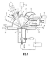
- the target plate can by a Additional heating 8 can be additionally heated as required.
- the target material With a power density of 106 to 107 watts / cm2 in focus, the target material is heated above the melting point, partially evaporates, and particles 9 form in the highly supersaturated vapor phase or particles 9 evaporate directly from the surface.
- the ZnSe window 3 is kept free of any vapor deposition layers by an inert purge gas (arrow 10) (insert 11 with nozzles for purge gas).
- the ultrafine particles 9 formed directly above the point of impact are transported by an inert transport gas 31, which is blown onto the target surface through a nozzle 12, through a heated suction opening (arrow 13) to a deposition chamber 14, where they strike a cooled substrate electrode 15 ( Cooling 16).
- a direct current or alternating current glow discharge can optionally be ignited between the substrate electrode 15 and the counter electrode 17 (voltage supply 18), and reactive gases for CVD or PCVD can additionally be let into the deposition chamber 14.
- Transport gases and reactive gases or gaseous reaction products are sucked off by a pump for gas disposal (arrow 19), and a pressure of about 1 to 100 hPa is maintained in the deposition chamber 14, while the pressure in the evaporator chamber 5 is about 100 to 1000 hPa (outlet pressure in the gas nozzle: some 105 Pa).
- the spot temperature is measured perpendicular to the area of incidence of the laser beam via an infrared pyrometer 20 (viewing window 21) and readjusted, for example, via the focus positioning.
- the target 7 is continuously computer-controlled, for example according to a meandering grid moved on.
- the resulting particles are, for example, a He-Ne laser beam 22, which enters the chamber 5 through a rinsed window 23 (rinsing insert not shown here) and parallel to the target plate 7 above the heated spot (beam height above the plate, for example, adjustable via a rotatable plane-parallel plate 24 is guided in front of the window 23) and strikes a photodetector 26 through a likewise rinsed viewing window 25, detected via light scattering and thus reduction in intensity of the HeNe beam.
- a He-Ne laser beam 22 enters the chamber 5 through a rinsed window 23 (rinsing insert not shown here) and parallel to the target plate 7 above the heated spot (beam height above the plate, for example, adjustable via a rotatable plane-parallel plate 24 is guided in front of the window 23) and strikes a photodetector 26 through a likewise rinsed viewing window 25, detected via light scattering and thus reduction in intensity of the HeNe beam.
- the portion of the CO2 laser beam reflected from the target surface is either reflected back onto the focal spot by a curved spherical concave mirror 27 or absorbed in an absorber 28 (e.g. Woodsches Horn) or "swamp" for more scattering surfaces.
- the polarization of the IR laser beam is expediently circular in order to avoid anisotropies during evaporation with a linearly polarized beam.
- a linearly polarized beam can also be used (see FIG. 3) and angles of incidence other than that shown in FIG. 1 can also be used.
- the plasma chamber (PCVD, CVD) and deposition chamber can also be arranged one after the other spatially separated from one another.
- the target plate 7 is a round "plate” which is rotatable at the angular velocity about the axis 29 shown there, the axis can also be linearly displaced parallel to the point of incidence of the laser beam .
- the point of impact is usually eccentric.
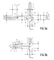
- FIG. 2 Another arrangement is shown in FIG. 2.
- the NdYAG or CO2 laser beam 1 does not strike almost vertically as in FIG. 1, but is focused in a weakly grazing incidence in the focus area in a correspondingly narrowed target nozzle 30.
- An inert (or reactive) transport gas 31 enters the target chamber 5 and flows out through the target nozzle 30 into the deposition chamber 14 and thereby transports the particles 9 formed in (and after the) hole to the substrate surface 15.
- the flat grazing incidence has the advantage of up to 50 times higher electric field strength on the surface compared to the vertical incidence, but of course the disadvantage of the area intensity decreasing with the angle of incidence.
- the target cone nozzle insert can be displaced in the beam incidence direction via a linear feedthrough, not shown in FIG. 2 - sliding in sealing rings 4.
- a focus shift can also be achieved by a linear shift of the converging lens 2 on the beam axis.
- a He-Ne laser beam 22 is irradiated directly behind the cone nozzle opening for particle detection, and the formation of particles is reduced of the beam registered.
- the substrate electrode 15, on which the particle beam strikes, is provided with a variable temperature setting 16 (cooling or heating) and can be displaced linearly in all three spatial directions (device 6 ').
- a counter electrode 17 enables a direct or alternating voltage (voltage supply 18) to be applied between the latter and the substrate 15 and thus the formation of a glow discharge.
- reactive gases can be introduced (not shown here), and the particles can be coated by CVD or PCVD or dissolved in the plasma and deposited on the substrate.
- the target 7 is a thin, linearly displaceable metal sheet on which the CO2 laser beam 1 in focus, slightly inclined to the surface normal, impinges, a focus adjustment by a relative displacement of the ZnSe Converging lens (Ge converging lens) 2 is reached in the direction of the beam axis. Due to the angle between the beam axis and target normal of a few degrees, back reflections of the laser beam and thus possible power fluctuations are avoided.
- the jet inlet window 3 (ZnSe) is also flushed from the inside with an inert flushing gas via a flushing gas nozzle insert 11 in order to avoid window coatings.
- the target 7 is arranged in the center of a three-dimensional crosspiece 32.
- the focal spot temperature is controlled via a pyrometer 20 by measuring the temperature on the back of the sheet (at the focal spot 33), and the focus is thus in the Usually readjusted to maximum temperature.
- a catcher plate 34 sits opposite the target 7 in the pumping direction 19, covers almost the entire pump cross section in a version according to the invention, with the exception of a central round aperture opening, behind which the actual substrate is seated.
- a particle blowing out in the direction of the collector can also be achieved via a transport gas nozzle 35.
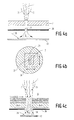
- FIGS. 4a and 4b An arrangement for embedding ultrafine particles 9, e.g. BaO or Sc2O3 or SiO2, e.g. Tungsten layer (or other metal layer) deposited via thermal CVD is shown in FIGS. 4a and 4b. It contains an inert transport gas, e.g. Argon, indicated by arrows 31. Between a (x-y) displaceable target 7, e.g. made of SiO2, BaO or Sc2O3, and a heated substrate 15, a fixed aperture 36 is arranged with an aperture 37 for forced transport gas flow.
- a (x-y) displaceable target 7 e.g. made of SiO2, BaO or Sc2O3
- a heated substrate a fixed aperture 36 is arranged with an aperture 37 for forced transport gas flow.
- ultrafine particles are not only evaporated from the surface of the target, but the target is totally pierced by the laser beam and the continuous delivery of ultrafine particles takes place by relative movement of the target perpendicular to the fixed laser beam (focus).
- the also fixed aperture behind the target with an opening in the area of the laser beam causes the inert transport gas to flow into the reaction / sedimentation chamber only through this opening, in which ultrafine particles are currently being evaporated, and not through the stomata already cut into the target .
- the inert transport gas transferring the ultrafine particles of target material e.g. BaO, Sc2O3 then strikes a substrate on which tungsten e.g. from WF6 + H2 (arrow 38) is deposited via CVD, here thermal CVD, and grows around the ultrafine particles also striking, so that a material structure of W with BaO / Sc2O3 particle embeddings is formed.
- target material e.g. BaO, Sc2O3
- alkaline earth replenishment cathodes can be produced in a single continuous process which replaces the many previous individual steps in the production, such as powder pressing and sintering for the porous W matrix, impregnation, application of the cover layer. This makes I-cathodes accessible for mass production.
- FIG. 4c in the arrangement according to FIGS. 4a and 4b, the target 7, which incidentally can also lie loosely on the diaphragm 36, is replaced by a target made of four different layers.
- target plates each consisting of BaO (1 mm thick), CaO (0.5 mm thick) and Al2O3 (0.5 mm thick), loosely stacked on top of each other and are shifted relative to the laser spot, for example in a meandering shape.
- these targets are relatively porous compacts.
- a target compact can also be used, which consists of a mixture of BaO: CaO: Al2O3 in a ratio of 4: 1: 1.
- the following process parameters were set: substrate temperature 500 to 600 ° C, WF6 flow 50 sccm, H2 flow 500 sccm, Ar flow 300 sccm, pressure in the deposition chamber part 14 10 to 20 hPa, pressure in the area 5 of the inflowing transport gas 100 to 200 hPa, Laser power 50 watts, focal length of the focusing lens 5.2 cm.
- substrate temperature 500 to 600 ° C WF6 flow 50 sccm, H2 flow 500 sccm, Ar flow 300 sccm
- pressure in the deposition chamber part 14 10 to 20 hPa pressure in the area 5 of the inflowing transport gas 100 to 200 hPa
- Laser power 50 watts focal length of the focusing lens 5.2 cm.
- a target removal rate of 0.07 g / min and a W deposition rate of about 0.3 g / min 1 mm thick I-cathode layers can be produced on an area of about 1 cm2 in a coating time of about
- the cover layer can also be deposited with 4 BaO.CaO.Al2O3 targets pulled out.
- the substrate is usually peeled off, either mechanically or by selective etching, or by using a substrate on which the W-CVD + particle embedding layer does not adhere.
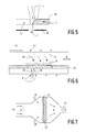
- FIG. 5 shows how target material struck by a laser beam 1 is completely removed in the radiation direction, the major part of the beam interacting with the target and only a small part 1 'passing the residual target 7'. Edge removal is thus carried out by the laser beam in relation to the target the target edge zone is moved along the target edge (arrow 39) and, with suitable setting of the laser parameters such as power, power density and the relative speed, completely removes the target edge.
- the already removed target part is designated 7 ".
- a layer 41 of ultrafine particles (FIG. 6) or of chain-containing agglomerates 41 '(FIG. 7) is deposited on or on a porous substrate 15' from a particle stream 40 with inert carrier gas.
- the layers 41 and 41 'and the porous substrates 15' are exposed to a reactive gas, e.g. WF6 / H2, flows through (arrows 38).
- 42 means an ohmic heating winding and 43 a coil for inductive heating.
- the separation of agglomerates of ultrafine particles and the CVI solidification can also be carried out in succession.
Landscapes
- Chemical & Material Sciences (AREA)
- Metallurgy (AREA)
- Chemical Kinetics & Catalysis (AREA)
- Engineering & Computer Science (AREA)
- Materials Engineering (AREA)
- Mechanical Engineering (AREA)
- Organic Chemistry (AREA)
- General Chemical & Material Sciences (AREA)
- Health & Medical Sciences (AREA)
- Toxicology (AREA)
- Chemical Vapour Deposition (AREA)
- Physical Vapour Deposition (AREA)
- Physical Or Chemical Processes And Apparatus (AREA)
- Manufacture Of Metal Powder And Suspensions Thereof (AREA)
Applications Claiming Priority (2)
| Application Number | Priority Date | Filing Date | Title |
|---|---|---|---|
| DE4000739 | 1990-01-12 | ||
| DE19904000739 DE4000739A1 (de) | 1990-01-12 | 1990-01-12 | Verfahren zum herstellen von mehrkomponentigen materialien |
Publications (1)
| Publication Number | Publication Date |
|---|---|
| EP0437890A1 true EP0437890A1 (fr) | 1991-07-24 |
Family
ID=6397957
Family Applications (1)
| Application Number | Title | Priority Date | Filing Date |
|---|---|---|---|
| EP90203468A Withdrawn EP0437890A1 (fr) | 1990-01-12 | 1990-12-21 | Méthode de production de matériaux multicomposants |
Country Status (3)
| Country | Link |
|---|---|
| EP (1) | EP0437890A1 (fr) |
| JP (1) | JPH04214860A (fr) |
| DE (1) | DE4000739A1 (fr) |
Cited By (7)
| Publication number | Priority date | Publication date | Assignee | Title |
|---|---|---|---|---|
| WO2000012775A1 (fr) * | 1998-08-26 | 2000-03-09 | Fraunhofer-Gesellschaft zur Förderung der angewandten Forschung e.V. | Procede et dispositif pour enduire des substrats sous vide |
| US6533908B1 (en) | 1998-08-26 | 2003-03-18 | Fraunhofer-Gesellschaft Zur Forderung Der Angewandten Forschung E.V. | Device and method for coating substrates in a vacuum utilizing an absorber electrode |
| CN109702215A (zh) * | 2019-01-25 | 2019-05-03 | 大连理工大学 | 热弧蒸发多腔体纳米粉体制备装置 |
| CN109702344A (zh) * | 2019-01-25 | 2019-05-03 | 大连理工大学 | 热弧与激光复合热源蒸发多腔体纳米粉体制备装置 |
| CN109759600A (zh) * | 2019-01-25 | 2019-05-17 | 大连理工大学 | 激光蒸发多腔体纳米粉体制备装置 |
| WO2023006197A1 (fr) * | 2021-07-28 | 2023-02-02 | MAX-PLANCK-Gesellschaft zur Förderung der Wissenschaften e.V. | Procédé de revêtement d'une région de revêtement sur une surface avant d'un substrat et appareil pour un système d'évaporation thermique |
| CN117359992A (zh) * | 2023-12-04 | 2024-01-09 | 山西炭科新材科技股份有限公司 | 一种柱状活性炭生产用成型装置 |
Families Citing this family (1)
| Publication number | Priority date | Publication date | Assignee | Title |
|---|---|---|---|---|
| KR100806113B1 (ko) * | 2006-12-26 | 2008-02-21 | 주식회사 코윈디에스티 | 박막증착 장치의 원료가스 공급장치 및 잔류가스 처리장치및 그 방법 |
Citations (4)
| Publication number | Priority date | Publication date | Assignee | Title |
|---|---|---|---|---|
| EP0143122A2 (fr) * | 1983-08-26 | 1985-06-05 | Shin-Etsu Chemical Co., Ltd. | Poudre ultrafine de carbure de silicium, procédé pour sa préparation et corps fritté obtenu à partir de celle-ci |
| JPS60116705A (ja) * | 1983-11-30 | 1985-06-24 | Hitachi Ltd | 金属の超微粉製造装置 |
| JPS6173881A (ja) * | 1984-09-19 | 1986-04-16 | Fuji Electric Co Ltd | 気相成長装置 |
| DE3800680A1 (de) * | 1988-01-13 | 1989-07-27 | Leyendecker Toni | Verfahren und vorrichtung zur beschichtung eines substrates |
-
1990
- 1990-01-12 DE DE19904000739 patent/DE4000739A1/de not_active Withdrawn
- 1990-12-21 EP EP90203468A patent/EP0437890A1/fr not_active Withdrawn
-
1991
- 1991-01-14 JP JP1610391A patent/JPH04214860A/ja active Pending
Patent Citations (4)
| Publication number | Priority date | Publication date | Assignee | Title |
|---|---|---|---|---|
| EP0143122A2 (fr) * | 1983-08-26 | 1985-06-05 | Shin-Etsu Chemical Co., Ltd. | Poudre ultrafine de carbure de silicium, procédé pour sa préparation et corps fritté obtenu à partir de celle-ci |
| JPS60116705A (ja) * | 1983-11-30 | 1985-06-24 | Hitachi Ltd | 金属の超微粉製造装置 |
| JPS6173881A (ja) * | 1984-09-19 | 1986-04-16 | Fuji Electric Co Ltd | 気相成長装置 |
| DE3800680A1 (de) * | 1988-01-13 | 1989-07-27 | Leyendecker Toni | Verfahren und vorrichtung zur beschichtung eines substrates |
Non-Patent Citations (4)
| Title |
|---|
| EXTENDED ABSTRACTS/ELECTROCHEMICAL SOCIETY, Band 87-2, 18. Oktober 1987, Seiten 1545-1546; D.P. STINTON: "Ceramic composites by chemical vapor infiltration" * |
| JOURNAL OF APPLIED PHYSICS, Band 66, Nr. 7, Oktober 1989, Seiten 3304-3308; G.-M. CHOW et al.: "Nanometer-size fiber composite synthesis by laser-inducec reactions" * |
| PATENT ABSTRACTS OF JAPAN, Band 10, Nr. 245 (C-368)[2301], 22. August 1986; & JP-A-61 73 881 (FUJI) 16-04-1986 * |
| PATENT ABSTRACTS OF JAPAN, Band 9, Nr. 272 (M-425)[1995], 30. Oktober 1985; & JP-A-60 116 705 (HITACHI SEISAKUSHO) 24-06-1985 * |
Cited By (12)
| Publication number | Priority date | Publication date | Assignee | Title |
|---|---|---|---|---|
| WO2000012775A1 (fr) * | 1998-08-26 | 2000-03-09 | Fraunhofer-Gesellschaft zur Förderung der angewandten Forschung e.V. | Procede et dispositif pour enduire des substrats sous vide |
| US6533908B1 (en) | 1998-08-26 | 2003-03-18 | Fraunhofer-Gesellschaft Zur Forderung Der Angewandten Forschung E.V. | Device and method for coating substrates in a vacuum utilizing an absorber electrode |
| US6558757B1 (en) | 1998-08-26 | 2003-05-06 | Fraunhofer-Gesellschaft Zur Forderung Der Angewandten Forschung E.V. | Method and device for coating substrates in a vacuum |
| CN109702215A (zh) * | 2019-01-25 | 2019-05-03 | 大连理工大学 | 热弧蒸发多腔体纳米粉体制备装置 |
| CN109702344A (zh) * | 2019-01-25 | 2019-05-03 | 大连理工大学 | 热弧与激光复合热源蒸发多腔体纳米粉体制备装置 |
| CN109759600A (zh) * | 2019-01-25 | 2019-05-17 | 大连理工大学 | 激光蒸发多腔体纳米粉体制备装置 |
| CN109702344B (zh) * | 2019-01-25 | 2023-12-29 | 大连理工大学 | 热弧与激光复合热源蒸发多腔体纳米粉体制备装置 |
| CN109702215B (zh) * | 2019-01-25 | 2023-12-29 | 大连理工大学 | 热弧蒸发多腔体纳米粉体制备装置 |
| CN109759600B (zh) * | 2019-01-25 | 2024-02-06 | 大连理工大学 | 激光蒸发多腔体纳米粉体制备装置 |
| WO2023006197A1 (fr) * | 2021-07-28 | 2023-02-02 | MAX-PLANCK-Gesellschaft zur Förderung der Wissenschaften e.V. | Procédé de revêtement d'une région de revêtement sur une surface avant d'un substrat et appareil pour un système d'évaporation thermique |
| CN117359992A (zh) * | 2023-12-04 | 2024-01-09 | 山西炭科新材科技股份有限公司 | 一种柱状活性炭生产用成型装置 |
| CN117359992B (zh) * | 2023-12-04 | 2024-03-05 | 山西炭科新材科技股份有限公司 | 一种柱状活性炭生产用成型装置 |
Also Published As
| Publication number | Publication date |
|---|---|
| JPH04214860A (ja) | 1992-08-05 |
| DE4000739A1 (de) | 1991-07-18 |
Similar Documents
| Publication | Publication Date | Title |
|---|---|---|
| EP0442163B1 (fr) | Méthode de production de particules ultrafines et leur utilisation | |
| DE69027004T2 (de) | Geometrie und Gestaltungen eines Geräts zum Magnetronzerstäuben | |
| EP0535019B1 (fr) | Procede et dispositif d'enduction de substrats | |
| DE4217450C2 (de) | Ionenbedampfungsverfahren und -vorrichtung | |
| DE69407734T2 (de) | Verfahren zur Herstellung diamantartiger Beschichtungen | |
| EP0306612B1 (fr) | Procédé de déposition de couches sur des substrats | |
| DE4340752C2 (de) | Vorrichtung zur Herstellung einer gleichförmigen Dünnschicht auf einer großen Substratfläche unter Verwendung eines Lasers | |
| DE69602131T2 (de) | System zur Elektronstrahlabscheidung aus der Gasphase | |
| DE2653242C2 (de) | Verfahren und Vorrichtung zum Überziehen eines Isoliersubstrats durch reaktive Ionenbeschichtung mit einer Oxidschicht | |
| DE3854307T2 (de) | Hohlkathodenkanone und Vorrichtung zur Materialablagerung durch Ionenbeschichtung. | |
| DE3611492A1 (de) | Verfahren und vorrichtung zum beschichten von werkzeugen fuer die zerspanungs- und umformtechnik mit hartstoffschichten | |
| EP0887438A1 (fr) | Procédé d'amélioration de la surface inférieure de corps creux et dispositif de la mise en oeuvre du procédé | |
| EP0727508A1 (fr) | Procédé et appareil de traitement de surfaces de substrats | |
| DE4016352A1 (de) | Laser-aufdampfeinrichtung | |
| EP0437890A1 (fr) | Méthode de production de matériaux multicomposants | |
| DE3785295T2 (de) | Verfahren zur herstellung eines films aus ultrafeinen teilchen. | |
| EP1558782B1 (fr) | Dispositif et procede de depot en phase vapeur sous vide d'un supraconducteur à haute température avec remplissage de matériau automatique | |
| EP0438627B1 (fr) | Dispositif d'évaporation par décharge d'arc ayant plusieurs creusets d'évaporation | |
| DE3800680A1 (de) | Verfahren und vorrichtung zur beschichtung eines substrates | |
| DE3925085C1 (fr) | ||
| WO1990013681A1 (fr) | Procede pour appliquer un materiau ceramique | |
| DE69314770T2 (de) | Reaktives Abscheidungsverfahren mittels ionisiertem Cluster-Strahl | |
| DE4006456C1 (en) | Appts. for vaporising material in vacuum - has electron beam gun or laser guided by electromagnet to form cloud or pre-melted spot on the target surface | |
| EP0444538A2 (fr) | Dispositif et procédé d'évaporation d'un matériau sous vide et utilisation du procédé | |
| DE69017973T2 (de) | Verfahren zur Herstellung von feinteiligen Teilchen oder Pulver, Dampf oder Feintröpfchen und Vorrichtung dafür. |
Legal Events
| Date | Code | Title | Description |
|---|---|---|---|
| PUAI | Public reference made under article 153(3) epc to a published international application that has entered the european phase |
Free format text: ORIGINAL CODE: 0009012 |
|
| AK | Designated contracting states |
Kind code of ref document: A1 Designated state(s): DE FR GB |
|
| STAA | Information on the status of an ep patent application or granted ep patent |
Free format text: STATUS: THE APPLICATION IS DEEMED TO BE WITHDRAWN |
|
| 18D | Application deemed to be withdrawn |
Effective date: 19920325 |