EP0437894B1 - Warenlager mit automatischer Anpassung - Google Patents
Warenlager mit automatischer Anpassung Download PDFInfo
- Publication number
- EP0437894B1 EP0437894B1 EP90203529A EP90203529A EP0437894B1 EP 0437894 B1 EP0437894 B1 EP 0437894B1 EP 90203529 A EP90203529 A EP 90203529A EP 90203529 A EP90203529 A EP 90203529A EP 0437894 B1 EP0437894 B1 EP 0437894B1
- Authority
- EP
- European Patent Office
- Prior art keywords
- warehouse
- brackets
- rod
- accordance
- sleeve
- Prior art date
- Legal status (The legal status is an assumption and is not a legal conclusion. Google has not performed a legal analysis and makes no representation as to the accuracy of the status listed.)
- Expired - Lifetime
Links
- 230000000284 resting effect Effects 0.000 claims description 4
- 238000003780 insertion Methods 0.000 claims description 3
- 230000037431 insertion Effects 0.000 claims description 3
- 230000008878 coupling Effects 0.000 claims 7
- 238000010168 coupling process Methods 0.000 claims 7
- 238000005859 coupling reaction Methods 0.000 claims 7
- 238000006243 chemical reaction Methods 0.000 claims 1
- 238000000151 deposition Methods 0.000 claims 1
- 230000001932 seasonal effect Effects 0.000 description 3
- 230000007246 mechanism Effects 0.000 description 2
- 238000000034 method Methods 0.000 description 2
- 230000007423 decrease Effects 0.000 description 1
- 230000000694 effects Effects 0.000 description 1
- 230000002452 interceptive effect Effects 0.000 description 1
- 239000000463 material Substances 0.000 description 1
- 238000004513 sizing Methods 0.000 description 1
- 239000002699 waste material Substances 0.000 description 1
Images

Classifications
-
- B—PERFORMING OPERATIONS; TRANSPORTING
- B65—CONVEYING; PACKING; STORING; HANDLING THIN OR FILAMENTARY MATERIAL
- B65G—TRANSPORT OR STORAGE DEVICES, e.g. CONVEYORS FOR LOADING OR TIPPING, SHOP CONVEYOR SYSTEMS OR PNEUMATIC TUBE CONVEYORS
- B65G1/00—Storing articles, individually or in orderly arrangement, in warehouses or magazines
- B65G1/02—Storage devices
Definitions
- Warehouses of the type comprising a plurality of shelvings identifying compartments in which take their place elements to be stored in the form of packages such as cases, boxes, baskets, etc. supported by pallets and which are termed generally load units are known.
- Handling of the elements from and to the cells of the warehouse is performed by lift devices which traverse on tracks along the shelving and have fork means for raising and deposit of the pallets.
- the space between superposed shelves be just higher than the load unit so that the space between the top of a load unit and the shelf above be minimal. This can be secured easily if the load units are all of the same predetermined height or are in a limited quantity of standard height and in a foreseeable number so that the warehouse can be laid out in advance with appropriately spaced shelves.
- the warehouse must be sized to receive the highest load unit and consequently space utilization in the warehouse decreases as the number of load units of a height less than the maximum increases.
- a known solution to the problem applicable to both cases is to provide on the side walls of the compartments small brackets, for support of auxiliary pallets and wider than those usually used with the load units, in such a manner as to provide shelving of an intermediate height by resting an auxiliary pallet on the small brackets.
- Such a solution results in the not negligible problem of having to foresee and store ready for use a number of auxiliary pallets equal to the expected maximum number of load units lower than the maximum height.
- enlargement of each compartment to allow insertion of load units on normal pallets without interference with the small support brackets considerably diminishes space utilization in the warehouse.
- the general object of the present invention is to obviate the above mentioned drawbacks by providing a warehouse with compartments for load units of varying height and handling means for loading and unloading thereof with compartment height adjustable rapidly to the height of the load unit while optimizing utilization of the warehouse volume.
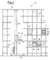
- a warehouse indicated generally by reference number 10 comprises shelving consisting of a plurality of risers 11 connected by horizontal stringers or brackets 12 to individualize a plurality of compartments 13 open at the front.
- a handling device 16 virtually of the known art having a lift 17 running along a vertical guide 18 for loading and unloading of load units 19, 19', 19'' of varying height in the compartments by means of extractable forks 20.
- each compartment 13 there are at regular intervals movable side brackets 22 facing each other in pairs.
- each bracket 22 is joined by a pin 39 to the corresponding riser 11 separating two adjacent compartments 13 so as to be movable between a raised or rest position (shown in broken lines) with minimal projection into the compartment and a lowered or working position (shown in solid lines).
- Each bracket has an operating pin 23 directed toward the aisle where the device 16 passes. It is thus possible by engaging the pins 23 of the brackets to move them and thus create further divisions of the compartments 13. In this manner it is possible to optimize warehouse space utilization by determining the space between the stringers as the maximum height of the load unit storable in the warehouse and the space between the brackets and between the brackets and the stringers as the minimum height of the load unit acceptable in the warehouse.
- two pairs of brackets can be provided for each compartment so as to permit division thereof in three spaces for low load units 19'', in two spaces for one medium-height load unit 19' and one low load unit 19'', or in a single space for one high load unit 19.
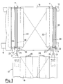
- brackets in the working or rest position it is for example advantageous to fit the handling device 16 at the bottom as shown in FIG. 2 (otherwise known) with two powered arm devices 21 rotating axially and terminating with U elements 24 spaced virtually the distance of the pins 39 of facing brackets in a compartment.
- the U elements 24 can engage with the pins 23 of the facing brackets to raise or lower them.
- a load unit to be stored is a unit of maximum height 19 it is placed in a completely empty compartment 13 and the arms 21 do not enter into action. But if a load unit lower than the maximum is to be stored, for example of type 19' or type 19'', it can occupy the empty upper space in a compartment already occupied by one or more load units of total height less than the maximum.
- the traversing device 16 need only bring the load unit near the empty space and engage the U parts of the arm 21 with the pins of the two movable brackets immediately above the upper unit already in the compartment, so as to bring the brackets into the support position and hence ready to receive the new load unit.
- the device 16 Upon withdrawal of a load unit from the warehouse, if it is resting on brackets 22 after the withdrawal operation the device 16 rotates with the arm 21 the corresponding brackets to the rest position so as to make the space available for a subsequent storage operation.
- Such an embodiment allows maximum flexibility since it is possible to store load units of various heights in an unforeseen number for each type and with the minimal space occupied.
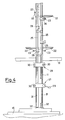
- FIG. 4 shows a different embodiment applying the innovative principles claimed herewith to achieve positioning of the brackets 22 in a manner other than with 21 on the device 16.
- a warehouse virtually of the type shown in FIG. 1 and hence with movable brackets 22 having positioning pins 23 comprises in accordance with the different embodiment described below as shown in FIG. 4 rods 25 placed parallel along each riser 11 and bearing U elements 26 at regular intervals. Said rods run parallel to the risers and are rotatable around their own axis by means of mechanical movement units 27 and 28 operated for example by cranks 29 inserted in hexagonal engagement seats 30.
- the rods 25 terminate at the bottom with threaded ends to be screwed into threaded sleeves in turn screwed onto threaded pins 32 fixed to the base of the riser 11.
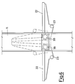
- the first movement unit unit 27 comprises a worm 33 coupled to a gear 34 in which the corresponding sleeve 31 slides.
- the sleeve 31 and gear 34 rotate integrally thanks to a guide 35 on the sleeve running in a corresponding seat in the gear 34.
- the second unit 28 comprises for each rod 25 a worm 36 coupled to a gear 37 in which runs the corresponding rod 25.
- the rod 25 and gear 37 rotate integrally thanks to a guide 38 on the rod running in a corresponding seat in the gear 37.
- the pitch of the U elements 26 along the rods 25 is different from the pitch of the brackets 22 along the risers 11 and such as to permit simultaneous engagement of the pins of all the brackets (either all raised or all lowered) occupying the same position in the compartments of an entire column of the warehouse without interfering with the other brackets of the compartments of said column.
- the brackets in each compartment form two shelves
- the U elements 26 will be two for each compartment and offset (as shown in fig. 4) in relation to the brackets so that when each U element 26 near for example the upper bracket of each compartment engages the corresponding movement unit pin 23 and moves to shift said brackets, the other U elements 26 near the lower brackets of each compartment do not interfere with the movement unit pins of said lower brackets. In this manner it is possible to simultaneously place in the desired position all the brackets of the same position on one side of the compartments of a column while leaving unchanged the position of the others.
- Said height can have for example with two pairs of brackets per compartment three different values for minimal waste of space and in each column of the warehouse there can be housed load units of two heights chosen among said three heights.
- each column depending on the movement unit of the brackets, can receive in each compartment a single load unit of maximum size, one medium-sized load unit 19' and one small load unit 19'', or three small load units 19''.
- the raising and rotation of the rod 25 can be achieved not only with a manual crank system but with a ratiomotor of the known art coaxial with the worms 33 and 36.
- the sleeve system described for raising the rods can be readily replaced by other known mechanisms. It would also be possible to provide a system similar to the one shown in FIG. 5 but with the sleeve lacking the lower threaded pins, losing the multiplying effect of the number of turns thereof for the purpose of axially moving the rods 25 but simplifying the mechanism since it is no longer necessary to provide the sleeves with the possibility of axial movement but only rotation.
Landscapes
- Engineering & Computer Science (AREA)
- Mechanical Engineering (AREA)
- Warehouses Or Storage Devices (AREA)
Claims (13)
- Magazin mit Regalen, die aus einer Vielzahl von durch horizontale Holme (12) verbundenen Ständer (11) zur Festlegung von einer geordneten Vielzahl von Fächern (13) bestehen, die in Zeilen und Spalten angeordnet sind und jeweils eine zur Regalwand gerichtete Stirnöffnung aufweisen, wobei längs dieser Regalwand eine Antriebsvorrichtung (16) bewegbar ist, um im Bereich der Stirnöffnung eines jeden Faches in Position gebracht zu werden und um Lasteinheiten (19) aus den Fächern zu entnehmen oder um sie dort durch die Stirnöffnung mittels ausfahrbaren Gabeln (20) abzustellen, dadurch gekennzeichnet, daß in jedem Fach an den Seitenwänden eine Vielzahl von paarweise gegenüberliegenden Konsolen (22) in Abständen angeordnet ist, wobei jede Konsole (22) jeweils unabhängig voneinander zwischen einer zur Seitenwand des Faches im wesentlichen parallelen, angehobenen bzw. Ruhe-Position und einer im wesentlichen horizontalen, abgesenkten bzw. Stützposition bolzenartig verschwenkbar ist, wobei der Abstand zwischen den gegenüberliegenden Konsolen (22) es einer Lasteinheit (19) ermöglicht wird, sobald sie sich in der angehobenen Position befindet, zwischen denselben bewegt zu werden, und sobald sie in abgesenkter Position sind, auf denselben aufzuliegen, wobei jede Konsole (22) Steckmittel (23) umfaßt, wobei Antriebsmittel (21, 24, 26) wahlweise mit den Steckmitteln (23) auf den vorgewählten Konsolen (22) in Eingriff gebracht werden, um zwischen der angehobenen Position und der abgesenkten Position bewegt zu werden, wobei die wahlweise Bewegung der Konsolen (22) in vertikal veränderbaren Abständen Stützflächen bilden, um die Fächer dazu auszurichten, Lasteinheiten (19) verschiedener Höhe aufzunehmen.
- Magazin nach Anspruch 1, dadurch gekennzeichnet, daß die Antriebsmittel (21) motorangetriebene Betätigungsmittel (24) umfassen, die an der Antriebsvorrichtung (16) angeordnet sind, um sich mit den Steckmitteln (23) auf den beiden gegenüberliegenden Konsolen (22) zu verbinden, sobald die Antriebsvorrichtung (16) sich in Stellung zur Einführung oder Entnahme einer Lasteinheit (19) auf den beiden Konsolen (22) befindet und sie zwischen der angehobenen Position und der abgesenkten Position im Sinne einer Verstellung in abgesenkter Position zu bewegen, sobald die Antriebsvorrichtung (16) sich in Position zur Einführung, oberhalb derselben, einer Lasteinheit (19) befindet und sie in angehobene Position zu verstellen, nachdem die Antriebsvorrichtung (16) eine Lasteinheit (19) oberhalb derselben entnommen hat.
- Magazin nach Anspruch 2, dadurch gekennzeichnet, daß die Steckmittel (23) für jede Konsole (22) mit einem Bolzen (23) ausgebildet sind, der in Richtung der Fachöffnung vorspringt und versetzt gegenüber der Verschwenkachse der Konsole (22) angeordnet ist, wobei die Betätigungsmittel jeweils eine Steckgabel (24) für den Bolzen (23) tragende Arme (21) umfassen, der im wesentlichen koaxial zur Verschwenkachse der ensprechenden Konsole (22) drehbar ist, wobei jeder Arm (21) in Richtung des Bolzens (23) der entsprechenden Konsole (22) beweglich ist, um ihn in Eingriff zu bringen und, mit Drehbewegung, die Konsole (22) zwischen der angehobenen und der abgesenkten Position zu verstellen.
- Magazin nach Anspruch 1, dadurch gekennzeichnet, daß die Antriebsmittel längs der Ständer (11) der Regale angeordnete und wahlweise die Steckmittel (23) in Eingriff bringende Betätigungsmittel (25, 26) umfassen, um bei Antrieb die Konsolen (22) zwischen der angehobenen und der abgesenkten Stellung zu verstellen.
- Magazin nach Anspruch 4, dadurch gekennzeichnet, daß die Betätigungsvorrichtungen längs der Ständer für jede Säule der Konsolen (22) auf derselben Vertikale eine Stange (25) umfassen, die in Abständen der Steckmittel (26) für den wahlweisen Eingriff in die Steckelemente (23) auf dien Konsolen (22) der Säule führt, wobei die Stangen (25) durch Einwirkung von Mitteln (27) zur gesteuerten Verschiebung der Stange im Sinne einer Verschiebung der in Eingriff gebrachten Konsolen (22) zwischen der angehobenen und der abgesenkten Position bei Axialverschiebung der Stange (25) axial verschiebbar sind.
- Magazin nach Anspruch 5, dadurch gekennzeichnet, daß die Stange (25) durch von der Stange gesteuerte Verschwenkmittel (28) axial verschwenkbar ist, um die in Form von im wesentlichen mit horizontal angeordneten Armen angeordneten U-Elementen ausgebildeten Mitteln für den wahlweisen Eingriff (26) zwischen einer von den Steckmitteln entfernten Außereingriffsposition, die für jede Konsole (22) in der Form eines in Richtung der Öffnung der Fächer vorspringenden und achsenversetzt gegenüber der Verschwenkachse der Konsole (22) angeordneten Bolzens ausgeführt sind, und einer Eingriffsposition mit den jeweiligen, von den Konsolen vorspringenden Bolzen (23) zu verstellen.
- Magazin nach Anspruch 5, dadurch gekennzeichnet, daß die Mittel zur gesteuerten Verschiebung der Stange (25) für jede Stange (25) eine innen mit einem Gewinde versehene und an ihrem Ende das eine Ende der Stange (25) schraubartig aufnehmende Hülse (31) umfassen, wobei das andere Ende der Hülse (31) auf einem Widerlager (32) angeordnet ist, um gegen die Ständer des Magazins zu wirken, wobei die Hülse (31) durch eine kinematische Verbindung mit Drehmitteln (33, 34) der Hülse um die eigene Achse im Sinne einer Ausschraubung oder Einschraubung des Endes der Stange (25) in ihr und daher um die axiale Verschiebung zu erzielen.
- Magazin nach Anspruch 7, dadurch gekennzeichnet, daß die Drehmittel der Hülse (31) ein auf der Hülse (31) aufgekeiltes und mit einem durch eine erste Antriebsvorrichtung (29) verdrehbaren Schneckengetriebe verbundenes Zahnrad umfassen.
- Magazin nach Anspruch 8, dadurch gekennzeichnet, daß die erste Antriebsvorrichtung ein Kurbeltrieb (29) ist.
- Magazin nach Anspruch 7, dadurch gekennzeichnet, daß das Widerlager eine Schraubspindel (32) umfaßt, um es innen in die Hülse (31) am anderen Ende desselben im Sinne einer Einschraubung und Ausschraubung der Hülse (31) mit gleichzeitiger, jeweiliger Einschraubung oder Ausschraubung der Stange (25) am anderen Ende einzuschrauben.
- Magazin nach Anspruch 7 und 10, dadurch gekennzeichnet, daß das auf der Hülse (31) verkeilte Zahnrad (34) in axialer Richtung auf derselben gleitbar ist, um die axiale Verschiebung der Hülse (31) bei ihrer Einschraubung und Ausschraubung auf der festliegenden Stange (32) zu ermöglichen.
- Magazin nach Anspruch 6, dadurch gekennzeichnet, daß die Mittel zur gesteuerten Verdrehung der Stange ein Zahnrad (37) umfassen, die auf der Stange (25) gleitbar in axialer Richtung verkeilt ist, um deren axiale und mit einem Schneckengetriebe (36) gekoppelte Verschiebung durch eine zweite Betätigungsvorrichtung (29) zu ermöglichen.
- Magazin nach Anspruch 12, dadurch gekennzeichnet, daß die zweite Antriebsvorrichtung ein Kurbeltrieb ist (29).
Applications Claiming Priority (2)
| Application Number | Priority Date | Filing Date | Title |
|---|---|---|---|
| IT1906390 | 1990-01-15 | ||
| IT01906390A IT1237950B (it) | 1990-01-15 | 1990-01-15 | Magazzino automatico adattabile |
Publications (2)
| Publication Number | Publication Date |
|---|---|
| EP0437894A1 EP0437894A1 (de) | 1991-07-24 |
| EP0437894B1 true EP0437894B1 (de) | 1993-12-08 |
Family
ID=11154227
Family Applications (1)
| Application Number | Title | Priority Date | Filing Date |
|---|---|---|---|
| EP90203529A Expired - Lifetime EP0437894B1 (de) | 1990-01-15 | 1990-12-29 | Warenlager mit automatischer Anpassung |
Country Status (4)
| Country | Link |
|---|---|
| US (1) | US5149240A (de) |
| EP (1) | EP0437894B1 (de) |
| DE (1) | DE69005094D1 (de) |
| IT (1) | IT1237950B (de) |
Cited By (3)
| Publication number | Priority date | Publication date | Assignee | Title |
|---|---|---|---|---|
| GB2279917A (en) * | 1992-07-18 | 1995-01-18 | Adams William M | Movable floor for goods storage area |
| EP0976667A1 (de) | 1998-07-30 | 2000-02-02 | Wolf Kunststoffe GmbH | Vorrichtung zur Aufnahme mehrerer Gegenstände in übereinanderliegenden Ebenen |
| EP0650420B1 (de) * | 1992-07-18 | 2000-03-22 | ADAMS, Mark William | Verbesserungen an einem lagersystem |
Families Citing this family (20)
| Publication number | Priority date | Publication date | Assignee | Title |
|---|---|---|---|---|
| DE4205001C2 (de) * | 1992-02-19 | 1995-11-09 | Dambach Ind Anlagen | Regalbediengerät mit einem Horizontalförderer als Speichereinrichtung mit mehreren Speicherplätzen |
| US5540532A (en) * | 1993-11-12 | 1996-07-30 | Transact International, Inc. | Apparatus for marine cargo container handling and storage |
| DE4416103C2 (de) * | 1994-04-19 | 1999-01-07 | Bellheimer Metallwerk Gmbh | Hochregal |
| US6042321A (en) * | 1996-07-30 | 2000-03-28 | Westafalia Technologies, Inc. | Automated storage and retrieval system for palletless dairy cases |
| US6099230A (en) * | 1998-03-04 | 2000-08-08 | Beckman Coulter, Inc. | Automated labware storage system |
| DE19834378A1 (de) * | 1998-07-30 | 2000-02-10 | Wolf Hans Joachim | Vorrichtung zur Aufnahme mehrerer Gegenstände in übereinander liegenden Etagen |
| DE19859620A1 (de) * | 1998-12-23 | 2000-07-06 | Wolf Kunststoffe Gmbh | Vorrichtung zur Aufnahme mehrerer Gegenstände in übereinanderliegenden Etagen |
| DE10130984B4 (de) * | 2001-06-27 | 2004-03-25 | Knapp Logistik Automation Ges.M.B.H. | Regalbediengerät und Verfahren zum Bedienen eines Produktlagerregals insbesondere einer Kommissioniervorrichtung |
| DE10136354B4 (de) * | 2001-07-26 | 2010-06-17 | Knapp Ag | Verfahren und Anlage zum Kommissionieren mit einem Behälterregal und zugeordnetem Regalbediengerät |
| DE20306390U1 (de) * | 2003-04-22 | 2003-06-26 | WITRON Logistik & Informatik GmbH, 92711 Parkstein | Flexibel nutzbares Regallager |
| NL1023865C2 (nl) * | 2003-07-09 | 2005-01-11 | Logiqs Agro B V | Gevelwagen voor gebruik in een kas. |
| DE102004007412A1 (de) * | 2004-02-16 | 2005-09-01 | Knapp Logistik Automation Ges.M.B.H. | Verfahren und System zum Bedienen eines Regals vorzugsweise in einer Kommissionieranlage |
| ITMI20061341A1 (it) * | 2006-07-11 | 2008-01-12 | Fata Spa | Carrello di insilaggio shuttle e impianto per la movimentqzione e immagazzinamento di container |
| DE102007040863B4 (de) * | 2007-08-29 | 2010-07-29 | Hänel & Co. | Lagerregal mit Transportvorrichtung |
| DE102013107438A1 (de) * | 2013-07-12 | 2015-01-29 | Witron Logistik + Informatik Gmbh | Variables Regallager |
| CN106628775B (zh) * | 2016-09-13 | 2019-01-22 | 浙江源端网络科技有限公司 | 一种移动式物品存取装置 |
| DE102018100448A1 (de) | 2018-01-10 | 2019-07-11 | Deutsche Post Ag | Sendungslager und Verfahren zum Übernehmen, Zwischenlagern und Ausgeben von Sendungen |
| DE102018103390A1 (de) * | 2018-02-15 | 2019-08-22 | Dematic Gmbh | Vorrichtung und Verfahren zum Lagern von Waren mit einem Regal |
| DE102020213046A1 (de) | 2020-10-15 | 2022-04-21 | Gebhardt Fördertechnik GmbH | Lager- und Entnahmesystem sowie ein Lagerregal |
| EP3988476B1 (de) * | 2020-10-26 | 2024-08-14 | BITO-Lagertechnik Bittmann GmbH | Verfahren zur einlagerung von ladungsträgern in einem regal |
Family Cites Families (10)
| Publication number | Priority date | Publication date | Assignee | Title |
|---|---|---|---|---|
| DD40437A (de) * | ||||
| US2675133A (en) * | 1951-07-16 | 1954-04-13 | Stora Kopparbergs Bergslags Ab | Stand for bar shaped material |
| US2957583A (en) * | 1958-05-12 | 1960-10-25 | John & Wm Burt Ltd | Racks for storing articles particularly cylinders |
| DE1122000B (de) * | 1959-07-25 | 1962-01-11 | Demag Zug Gmbh | Geraet zum lueckenhaften Stapeln von flachen Guetern gleicher Groesse, insbesondere von Blechpaketen |
| SU474484A2 (ru) * | 1967-10-30 | 1975-06-25 | Предприятие П/Я Р-6194 | Контейнер дл много русного хранени и перевозки железобетонных и других изделий |
| US3734312A (en) * | 1972-01-31 | 1973-05-22 | Hickinbotham Bros Ltd | Steel bar storage rack unit and cooperating lifting device |
| JPS604081B2 (ja) * | 1975-07-14 | 1985-02-01 | 三機工業株式会社 | ガイド板を兼用した商品支持レ−ルを具えた定量切出しラツク |
| DE2716632A1 (de) * | 1977-04-15 | 1978-10-19 | Dexion Gmbh | Programmierbare behaeltereinheit zur verwendung in einem organisationssystem fuer materialfluss und lagerung |
| JPS54136082A (en) * | 1978-04-10 | 1979-10-22 | Murata Mach Ltd | Cargo receiving and forwarding system for automatic storehouse |
| JPS62121109A (ja) * | 1985-11-18 | 1987-06-02 | Daifuku Co Ltd | ストツパ−付き棚を備えた自動倉庫 |
-
1990
- 1990-01-15 IT IT01906390A patent/IT1237950B/it active IP Right Grant
- 1990-12-29 DE DE90203529T patent/DE69005094D1/de not_active Expired - Lifetime
- 1990-12-29 EP EP90203529A patent/EP0437894B1/de not_active Expired - Lifetime
-
1991
- 1991-01-14 US US07/640,813 patent/US5149240A/en not_active Expired - Fee Related
Cited By (4)
| Publication number | Priority date | Publication date | Assignee | Title |
|---|---|---|---|---|
| GB2279917A (en) * | 1992-07-18 | 1995-01-18 | Adams William M | Movable floor for goods storage area |
| GB2279917B (en) * | 1992-07-18 | 1995-10-11 | Adams William M | Improvements relating to goods storage |
| EP0650420B1 (de) * | 1992-07-18 | 2000-03-22 | ADAMS, Mark William | Verbesserungen an einem lagersystem |
| EP0976667A1 (de) | 1998-07-30 | 2000-02-02 | Wolf Kunststoffe GmbH | Vorrichtung zur Aufnahme mehrerer Gegenstände in übereinanderliegenden Ebenen |
Also Published As
| Publication number | Publication date |
|---|---|
| IT9019063A0 (it) | 1990-01-15 |
| DE69005094D1 (de) | 1994-01-20 |
| IT1237950B (it) | 1993-06-19 |
| US5149240A (en) | 1992-09-22 |
| IT9019063A1 (it) | 1991-07-15 |
| EP0437894A1 (de) | 1991-07-24 |
Similar Documents
| Publication | Publication Date | Title |
|---|---|---|
| EP0437894B1 (de) | Warenlager mit automatischer Anpassung | |
| JP6491764B2 (ja) | 縦型物品保管・配分装置及び医薬品配分用機器 | |
| WO2009150684A1 (en) | Device and method used to pick up handle and store packages in an automated warehouse | |
| EP3031037B1 (de) | Automatisches lager | |
| JPH07187331A (ja) | 自動倉庫における移載装置 | |
| EP2726385A1 (de) | Lagerungssystem mit vertikalem hub und verfahren zum betrieb eines hubs | |
| US6619902B1 (en) | Automated storage and retrieval system and indexing/insertion extraction mechanism therefor | |
| US20240270495A1 (en) | Systems and methods for providing dynamic mobile exchange systems | |
| EP3527506A1 (de) | Handhabungssystem für mehrstufige lager und mehrstufiges lager mit solch einem handhabungssystem | |
| KR102938431B1 (ko) | 컨테이너 보관 및 인출 시스템 | |
| US3844423A (en) | Pallet accumulator | |
| JPH07187329A (ja) | 自動倉庫における移載装置 | |
| EP1669308B1 (de) | Verfahren und Vorrichtung zur Bestückung und Entnahme von Lagergut von Regalfächern eines Lagerregals | |
| WO2024226964A2 (en) | Systems and methods for providing dynamic mobile exchange systems | |
| CN112690571A (zh) | 储料系统 | |
| EP2452899B1 (de) | Vorrichtung zum automatischen Handhaben von Ladeeinheiten in Regallagern | |
| WO2013130111A1 (en) | Methods and apparatus for handling stackable articles | |
| US6347713B1 (en) | Multilevel modular storage system with modules sliding horizontally in both directions | |
| CN213935050U (zh) | 无人售货机用盒装食品货仓 | |
| EP4701960A2 (de) | Systeme und verfahren zur bereitstellung dynamischer mobilaustauschsysteme | |
| KR20250119496A (ko) | 식품박스 저장 및 인출 시스템 | |
| KR830000698B1 (ko) | 자동판매기의 상품 선반 | |
| WO2025056148A1 (en) | Automated storage system | |
| JPH01214507A (ja) | 省スペース自動定量収納方法および装置 |
Legal Events
| Date | Code | Title | Description |
|---|---|---|---|
| PUAI | Public reference made under article 153(3) epc to a published international application that has entered the european phase |
Free format text: ORIGINAL CODE: 0009012 |
|
| AK | Designated contracting states |
Kind code of ref document: A1 Designated state(s): BE DE ES FR GB |
|
| 17P | Request for examination filed |
Effective date: 19911220 |
|
| 17Q | First examination report despatched |
Effective date: 19920811 |
|
| GRAA | (expected) grant |
Free format text: ORIGINAL CODE: 0009210 |
|
| AK | Designated contracting states |
Kind code of ref document: B1 Designated state(s): BE DE ES FR GB |
|
| PG25 | Lapsed in a contracting state [announced via postgrant information from national office to epo] |
Ref country code: FR Effective date: 19931208 Ref country code: ES Free format text: THE PATENT HAS BEEN ANNULLED BY A DECISION OF A NATIONAL AUTHORITY Effective date: 19931208 Ref country code: DE Effective date: 19931208 Ref country code: BE Effective date: 19931208 |
|
| REF | Corresponds to: |
Ref document number: 69005094 Country of ref document: DE Date of ref document: 19940120 |
|
| EN | Fr: translation not filed | ||
| PLBE | No opposition filed within time limit |
Free format text: ORIGINAL CODE: 0009261 |
|
| STAA | Information on the status of an ep patent application or granted ep patent |
Free format text: STATUS: NO OPPOSITION FILED WITHIN TIME LIMIT |
|
| 26N | No opposition filed | ||
| PGFP | Annual fee paid to national office [announced via postgrant information from national office to epo] |
Ref country code: GB Payment date: 19941220 Year of fee payment: 5 |
|
| PG25 | Lapsed in a contracting state [announced via postgrant information from national office to epo] |
Ref country code: GB Effective date: 19951229 |
|
| GBPC | Gb: european patent ceased through non-payment of renewal fee |
Effective date: 19951229 |