EP0437924A2 - Système automatique pour la mise au point et incorporation dans des caméras - Google Patents
Système automatique pour la mise au point et incorporation dans des caméras Download PDFInfo
- Publication number
- EP0437924A2 EP0437924A2 EP90311765A EP90311765A EP0437924A2 EP 0437924 A2 EP0437924 A2 EP 0437924A2 EP 90311765 A EP90311765 A EP 90311765A EP 90311765 A EP90311765 A EP 90311765A EP 0437924 A2 EP0437924 A2 EP 0437924A2
- Authority
- EP
- European Patent Office
- Prior art keywords
- range
- finding system
- range finding
- blur
- focusing
- Prior art date
- Legal status (The legal status is an assumption and is not a legal conclusion. Google has not performed a legal analysis and makes no representation as to the accuracy of the status listed.)
- Granted
Links
Images

Classifications
-
- G—PHYSICS
- G02—OPTICS
- G02B—OPTICAL ELEMENTS, SYSTEMS OR APPARATUS
- G02B7/00—Mountings, adjusting means, or light-tight connections, for optical elements
- G02B7/28—Systems for automatic generation of focusing signals
- G02B7/285—Systems for automatic generation of focusing signals including two or more different focus detection devices, e.g. both an active and a passive focus detecting device
Definitions
- the present invention relates to an automatic focusing system or device useful for a camera such as a still camera, a video camera, a cine camera or the like motion picture camera and more particularly to an automatic focusing system having an active range finding system utilizing triangulation combined with a passive range finding system utilizing an image phase difference detecting method for operating the focusing mechanism according to range data obtained thereby.
- Japanese Laid-Open Patent Publication No. 212912/1988 discloses a device having an active range finding system utilizing triangulation and a passive range finding system utilizing an image phase difference detecting method for operating the focusing mechanism according to thus obtained range data.
- a device according to the said invention adjusts the lens focus to a predetermined extent according to the range data obtained through the active range finding system, and then adjusts it once again by the passive range finding system. In other words, the device measures the distance to the object firstly by the passive range finding system.
- the lens is driven, according to the range data obtained through the active range finding system, to a point where focusing by the passive range finding system is possible. If the image produced by the passive range finding system alone has a small degree of blur, focusing is completed immediately by the passive range finding system.
- the degree of image blur detectable by the phase difference detecting method does not operate satisfactorily at focus distances near infinity or closely within infinity.
- the prior-art technique suffers the drawback that the amount of passive range finding data is extremely large when the degree of blur is large. As a result, range calculation, based on highly blurred images requires a long processing time.
- This can reduce the burden on the processing part of the device, used for the passive range measurement, by always bringing the system into at least rough focus before the passive range measurement is required. As a result the reduced measuring time for determining the degree of blur makes quick focusing possible.
- An embodiment of automatic focusing device includes an active range finding system together with a passive range finding system.
- the active range finding system may e.g. utilize triangulation for determining the distance to an object to be photographed.
- a light emitting element may emit a light beam to the object.
- a photoelectric converting element may receive the light beam reflected by the object.
- the range can be determined by triangulation.
- the passive range finding system may utilize an image phase difference detecting method for determining the degree of blur by forming a plurality of images of the object arriving along a plurality of different light paths. The passive range finding system can detect each of these images by photoelectric converting elements to determine a phase difference between each image.
- a focusing mechanism can drive a focusing lens within a photographic lens to a position determined by either one or both of the active and passive range finding systems.
- a movement measuring means can measure the distance moved by the focusing lens.
- a comparing means can calculate the actual variance between data of the current position of the focusing lens, which is monitored through its movement, and range data obtained by the active range finding system. The comparing means may also determine the relative magnitude between the calculated actual variance and a preset degree of blur.
- a focus operation switching means may transfer control of focusing between active and passive range finding systems. The focus operation switching means can enable focusing according to the output of the active range finding system when the comparing means judges the actual variance to be greater than the preset degree of blur.
- the focus operation switching means can enable focusing then the actual variance is judged to be smaller than the preset degree of blur by the comparing means. Additionally, focusing can be performed on the basis of the output of the passive range finding system whenever the focusing mechanism arrives at a position commanded by the active range finding system.
- the active range finding system is actuated, then, the distance to the object measured by the active range finding system is compared with the data of the current position of the lens.
- the difference is determined between the actual degree of blur and a preset degree of blur.
- the preset degree of blur can be, more precisely, a preset converted value of lens movement.
- the comparison indicates that the variance (actual degree of blur) is greater than the preset degree of blur, the lens is moved in the direction where it should focus.
- the variance is smaller than the preset degree of blur or when said focusing movement according to the data obtained by the active range finding system is completed, focusing movement takes place according to data obtained from the passive range finding system.
- Embodiments of the present invention can provide an automatic focusing device employing an active range finder to establish an initial range to an object.
- a blur can be calculated based on the initial range. If the blur is less than a predetermined value, the active range finder can be bypassed in favour of a passive range finder.
- a focusing drive can be responsive to the output of the passive range finder to drive the focus toward zero blur. If the initial range provides a blur calculation exceeding the predetermined value, the focusing drive can respond to the active range finder until the calculated blur is reduced to a second predetermined value, at which time the active range finder can be bypassed in favour of the passive range finder. Thereafter, the focusing drive can respond to the passive range finder.
- an automatic focusing device comprising: an active range finding system, a passive range finding system, a focusing mechanism, the focusing mechanism including means for driving a photographic lens to a focus, means for actuating the active range finding system to produce a first range value, means, responsive to the first range value being between first and second amounts, to actuate the passive range finding system, and to thereafter bypass the active range finding system, means responsive to the first range value being outside the first and second amounts to actuate the focusing mechanism, and means responsive to a relation of the focusing mechanism to the first range value to actuate the passive range finding system and thereafter bypass the active range finding system, and the focusing mechanism being responsive to the passive range finding system whenever the passive range finding system is actuated.
- the relation of the focusing mechanism to the first range value is preferably the variance between the actual position of the focusing lens and that first range value.
- the focusing mechanism can firstly perform the focusing operation in the focusing direction according to the active range finding data and subsequently that mechanism can focus in the focusing direction according to the passive range finding data.
- a method for focusing a lens comprising: measuring a range with an active range finding system, calculating a blur based on the range, driving a focusing mechanism based on the range in a direction to reduce the blur, if the blur exceeds a predetermined value, transferring range measurement to a passive range finding system if the blur is within the predetermined range, and the step of transferring being performed immediately if the blur is initially within the predetermined range.
- an automatic focusing system comprising: first means for measuring a range with an active range finding system, means for calculating a blur based on the range, means for focusing a lens based on the range in a direction to reduce the blur, if the blur exceeds a predetermined value, means for measuring a range with a passive range finding system, means for transferring range measurement from the active range finding system to the passive range finding system if the blur is within the predetermined range, and means for immediately transferring the range measurement if the blur is initially within the predetermined range.
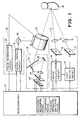
- an overall view shows the entire structure of an automatic focusing device having an active range finding system 11 utilizing triangulation and a passive range finding system 12 utilizing an image phase difference detecting method.
- Active range finding system 11 includes a light emitting element 13 actuated by a light switch circuit 14 to emit light beams, such as, for example, infrared rays, through a light emitting lens 15 toward an object 16.
- a photoelectric converting element 18 receives light reflected from object 16 through a light receiving lens 17.
- a photoelectric converting element 18 produces range signals delta 11 and delta 12 for distances to object 16 in accordance with incidence positions of reflected light from object 16.
- the range signals are applied to a standard range calculation circuit 19.
- Range calculation circuit 19 feeds the range signals delta 11 and delta 12 into a microcomputer 21 in the form of m-bit digital signals.
- Light switch circuit 14 and range calculation circuit 19 perform specified controlling activity in accordance with commands produced by microcomputer 21 with timing as subsequently described.
- Passive range finding system 12 conveys images of the object entering through a photographic lens 23, reflects it from a quick return mirror 24 and an auxiliary mirror 25, through a projecting lens 26 to a pair of image focusing lenses 27 and onto a pair of photoelectric converting elements 28.
- the degree of blur is detected by comparing the phase difference between the two images on the respective photoelectric converting elements 28 (hereinafter called image sensors).
- Image sensors 28 are controlled by commands from microcomputer 21 with timing as subsequently described. The degree of blur is determined by actuation of image sensors 28. In this way, measured range data is input to microcomputer 21.
- a focusing mechanism 30 includes a motor driving circuit 31 controlled by range data supplied by microcomputer 21.
- the range data may be measured by either active range finding system 11 or passive range finding system 12.
- Motor driving circuit 31 actuates a lens driving motor 32 to move a focusing lens (not shown in Fig. 1) within photographic lens 23 to move toward focussed position.
- Focusing mechanism 30 includes a pulse generating circuit 33 which produces a number of pulse signals corresponding to a distance which the focusing lens is to be moved.
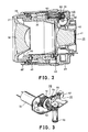
- photographic lens 23 includes a frame 37 attached to a front part (the left part of the figure) of a fixed cylinder 35 by a helicoid 36.
- Frame 37 supports a multiple lens element 38.
- a zoom cam cylinder 39 is disposed inside said fixed cylinder 35. Zoom cam cylinder 39 is revolvable in the circumferential direction of cylinder 35.
- a rear frame 40 coupled to the rear (at the right of the figure) of zoom cam cylinder 39, supports a multiple lens element 41.
- Zoom cam cylinder 39 is integrally coupled to a zoom ring 44 revolvably attached around the outer surface of a fixed external cylinder 43.
- Cam interlocking permits revolving of zoom cam cylinder 39 to control the zooming function by moving multiple lens elements 38 and 41, disposed in said front frame 37 and rear frame 40, forward and backward.
- Lens motor 32 is supported on a fixed seat 45 located inside the rear part of fixed external cylinder 43.
- Lens motor 32 drives a gear mechanism 46 to revolve a range ring 47, which is revolvably disposed inside fixed external cylinder 43.
- Range ring 47 is integrally coupled with front frame 37. Front frame 37 is rotated on helicoid 36 by rotation of range ring 47, thereby causing focusing.
- gear mechanism 46 has a pinion gear 50 integrally formed with the shaft of lens driving motor 32.
- Pinion gear 50 is in driving relationship with pinion bevel gears 51 and 52 and a pinion gear 53.
- Pinion bevel gear 53 drives range ring 47 (not shown in Fig. 3).
- Pinion bevel gear 51 is also engaged, through an idle pinion 54, to an impeller 55.
- Impeller 55 includes leaves which pass inside a groove of a photo interrupter 57.
- a light emitting element and a light receiving element face each other in the groove of photo interrupter 57 thereby producing a pulse signal whenever a blade of impeller 55 passes therebetween.
- Rotation of impeller 55 produces a number of pulses corresponding to the distance through which lenses 38 and 41 are moved.
- the combination of impeller 55 and photo interrupter 57 comprise the pulse generating circuit 33 of Fig. 1.
- Microcomputer 21 counts the number of pulse signals produced by pulse generating circuit 33 to measure the distance over which the elements of photographic lens are moved.
- microcomputer 21 to compute the current position of the focusing lens.
- the current position is used to compute the variance between the computed current position and the position commanded by active range finding system 11.
- Microcomputer 21 compares the computed variance and a preset degree of blur to determine which is greater, In short, microcomputer 21 compares data of the current position of the focusing lens and range data obtained by the active range finding system to compute the variance thereof and to recognize the relative magnitude of the computed variance and the preset degree of blur.
- Microcomputer 21 actuates focusing mechanism 30 to respond to range data supplied from active range finding system 11 when the variance between the data of the current position of the focusing lens and the range data from active range finding system 11 is judged to be greater than the preset degree of blur. Conversely, microprocessor actuates focusing mechanism 30 to respond to passive range finding system 12 either on completion of focusing operation based on range data from the active range finding system 11 or when the variance is judged by the comparing means to be smaller than the preset degree of blur.
- Fig. 4 shows an outline of a configuration where an automatic focusing device having said two range finding systems 11 and 12 is disposed in a camera.
- Figs. 5A and 5B shows the relationship of output signals generated by passive range finding system 12 on the two image sensors 28 shown in Figs. 1 and 4 under focused and unfocused conditions, respectively. If photographic lens 23 is in a focused state, a phase difference between outputs A1 and A2 of the pair of image sensors 28 is approximately zero, as shown in Fig. 5A. If photographic lens 23 is in the unfocused state, however, as shown in Fig. 5B, a phase difference X exists between outputs A1 and A2 of the pair of image sensors 28. The value of phase difference X is interpreted by microcomputer 21 as measured range.
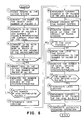
- microcomputer 21 commands active range finding system 11 to measure the distance to the object.
- Active range finding system 11 performs its range measuring operation (step 1) and outputs m bit of object range data from range calculating circuit.
- the m bits of range data correspond to the object range.
- Microcomputer 21 calculates and stores a number of pulses A corresponding to the m bit of object range data (measured range data) (step 2).
- microcomputer 21 compares the stored number of pulses A that corresponds to the measured range data and the data of the current position of the focusing lens inside photographic lens 23 (the number of pulses B), and computes variance
- the position of the focusing lens is monitored through the number of pulses produced by pulse generating circuit 33, the relation between the position of the lens and number of pulses is so adjusted that the number of pulses to be produced when adjusting the lens from the closest focusing distance to infinity shall be 1,600 pulses.
- the number of pulses A corresponding to measured range data from active range finding system 11 is adjusted to equal the number representing lens location data B, when the distance to the object is same.
- lens position pulses B in the focused state are 948.
- the number of pulses A for the measured range data of active range finding system 11 at the object range of 1.3 m is also adjusted to be 948.
- is compared with a preset degree of blur a, and their relative magnitude is judged (step 4 and 5). If the variance is greater than a, the focusing lens is moved in the focusing direction according to measured range data A. That is, focusing mechanism 30 is operated by an amount corresponding to the number of pulses for
- pulse generating circuit 33 produces a number of pulses corresponding to the distance to be moved by the lens, and that number is monitored (step 7).
- the operation of focusing mechanism 30 is terminated when the number of monitored pulses reaches a value equivalent to variance
- microcomputer 21 commands passive range finding system 12 to measure the distance so that passive range finding system 12 performs its prefixed measuring operation (step 11) and computes the degree of blur +/- C according to the phase difference X between outputs A1 and A2 shown in Fig. 5 (step 12).
- passive range finding system 12 The same passive range measurement operation by passive range finding system 12 is performed also when the variance
- operation of passive range finding system 12 is actuated in one of two ways, 1) completion of focusing by active range finding system 11, or 2) an initial finding that the variance
- step 13 judgment is made as to whether the lens is focused (step 13), and if it is judged to be in a focused state (if degree of blur +/- C is zero), the focusing operation is terminated (step 14). If the focused condition has not yet been reached, focusing mechanism 30 is operated to the extent corresponding to the number of pulses for said degree of blur +/- C (range data measured by passive range finding system 12) to bring the lens into focus (step 15). At this time too, pulse generating circuit 33 produces a number of pulses corresponding to the distance moved by the lens, and that number is monitored (step 16). Operation of focusing mechanism 30 is terminated when the number of monitored pulses reached a figure equivalent to the degree of blur +/- C (step 17 and 18).
- Step 19 the value produced by the computation being stored as the revised data B of the current position of the lens (step 19). The system then returns to step 11. Steps 11 to 19 are repeated until the lens is judged to be in focus at step 13.
- the degree of blur a which is used as a standard for judgment in step 5, is set at approximately 500 pulses as shown in the chart.
- the current lens position data B is 948 pulses in the chart.
- the lens is moved in the focusing direction, first according to active range measurement data A, and then according to passive range measurement.
- passive range finding system 12 performs range measurement operation within the scope of maximum of 500 pulses in the + and - directions. Therefore, since passive range data does not become excessively large, it is possible to shorten range computing time and to perform focusing without putting much burden on passive range finding system 12.
- the operational switch from focusing by active range data to focusing by passive range data is executed in accordance with a specified procedural flow, the system is free from hunting for the final focus following switching or selection of operation.
- active range finding is performed first, and then, in accordance with its result, passive range finding is performed either immediately or after movement in the focusing direction according to the active range data. Therefore, it is possible to prevent the need for processing an excessive amount of passive range measurement data and to thereby reduce time required to measure the degree of blur as well as to reduce the burden on the computing section of the device, whereby quick focusing is provided.
- active range finding system 11 may be substituted for active range finding system 11 without departing from the spirit and scope of the invention.
- a time-of-transit electro-optical system which measures the out-and-back transit time of a pulse of light may serve as active range finding system 11.
- an acoustic range finder, or a radio-frequency range finder may be substituted without departing from the scope of the invention.
Landscapes
- Physics & Mathematics (AREA)
- General Physics & Mathematics (AREA)
- Optics & Photonics (AREA)
- Focusing (AREA)
- Automatic Focus Adjustment (AREA)
- Measurement Of Optical Distance (AREA)
Applications Claiming Priority (2)
| Application Number | Priority Date | Filing Date | Title |
|---|---|---|---|
| JP8020/90 | 1990-01-17 | ||
| JP2008020A JP2958463B2 (ja) | 1990-01-17 | 1990-01-17 | 自動焦点調節装置 |
Publications (3)
| Publication Number | Publication Date |
|---|---|
| EP0437924A2 true EP0437924A2 (fr) | 1991-07-24 |
| EP0437924A3 EP0437924A3 (en) | 1992-03-04 |
| EP0437924B1 EP0437924B1 (fr) | 1995-12-20 |
Family
ID=11681655
Family Applications (1)
| Application Number | Title | Priority Date | Filing Date |
|---|---|---|---|
| EP90311765A Expired - Lifetime EP0437924B1 (fr) | 1990-01-17 | 1990-10-26 | Système automatique pour la mise au point et incorporation dans des caméras |
Country Status (4)
| Country | Link |
|---|---|
| US (1) | US5121154A (fr) |
| EP (1) | EP0437924B1 (fr) |
| JP (1) | JP2958463B2 (fr) |
| DE (1) | DE69024341T2 (fr) |
Cited By (1)
| Publication number | Priority date | Publication date | Assignee | Title |
|---|---|---|---|---|
| GB2343072A (en) * | 1998-09-28 | 2000-04-26 | Asahi Optical Co Ltd | Combined passive and active focussing system |
Families Citing this family (7)
| Publication number | Priority date | Publication date | Assignee | Title |
|---|---|---|---|---|
| US5396053A (en) * | 1988-10-21 | 1995-03-07 | Symbol Technologies, Inc. | Method of adjusting electrical circuit parameters during manufacture of a bar code scanner |
| JP3180201B2 (ja) * | 1992-09-14 | 2001-06-25 | セイコープレシジョン株式会社 | モータ駆動シャッタ |
| US5745806A (en) * | 1995-06-15 | 1998-04-28 | Fuji Photo Optical Co., Ltd. | Distance measuring apparatus |
| DE19730976C2 (de) * | 1996-07-19 | 2003-12-24 | Pentax Corp | Einrichtung zum Scharfstellen des Objektivs einer Kamera |
| US7538813B2 (en) * | 2005-05-11 | 2009-05-26 | Sony Ericsson Mobile Communications Ab | Digital cameras with triangulation autofocus systems and related methods |
| US8210437B2 (en) * | 2010-03-04 | 2012-07-03 | Symbol Technologies, Inc. | Data capture terminal with automatic focusing over a limited range of working distances |
| KR20150010230A (ko) * | 2013-07-18 | 2015-01-28 | 삼성전자주식회사 | 단일 필터를 이용하여 대상체의 컬러 영상 및 깊이 영상을 생성하는 방법 및 장치. |
Family Cites Families (8)
| Publication number | Priority date | Publication date | Assignee | Title |
|---|---|---|---|---|
| DE2933077A1 (de) * | 1978-09-04 | 1980-03-13 | Hauser Raimund | Fokussiereinrichtung |
| US4592638A (en) * | 1983-09-03 | 1986-06-03 | Canon Kabushiki Kaisha | Automatic focus adjusting device |
| JPS6060616A (ja) * | 1983-09-13 | 1985-04-08 | Canon Inc | 自動焦点調節装置 |
| JPS6098413A (ja) * | 1983-11-02 | 1985-06-01 | Canon Inc | 合焦検出装置 |
| JPS62192716A (ja) * | 1986-02-20 | 1987-08-24 | Minolta Camera Co Ltd | 焦点検出装置 |
| JPH079499B2 (ja) * | 1986-04-25 | 1995-02-01 | ソニー株式会社 | オ−トフオ−カス装置 |
| JP2586931B2 (ja) * | 1988-07-07 | 1997-03-05 | 株式会社リコー | カメラの測距装置 |
| US4992817A (en) * | 1988-08-06 | 1991-02-12 | Canon Kabushiki Kaisha | Focus detecting device switching between passive and active detection |
-
1990
- 1990-01-17 JP JP2008020A patent/JP2958463B2/ja not_active Expired - Lifetime
- 1990-10-01 US US07/591,451 patent/US5121154A/en not_active Expired - Lifetime
- 1990-10-26 DE DE69024341T patent/DE69024341T2/de not_active Expired - Fee Related
- 1990-10-26 EP EP90311765A patent/EP0437924B1/fr not_active Expired - Lifetime
Cited By (3)
| Publication number | Priority date | Publication date | Assignee | Title |
|---|---|---|---|---|
| GB2343072A (en) * | 1998-09-28 | 2000-04-26 | Asahi Optical Co Ltd | Combined passive and active focussing system |
| US6350976B1 (en) | 1998-09-28 | 2002-02-26 | Asahi Kogaku Kogyo Kabushiki Kaisha | Distance measuring apparatus |
| GB2343072B (en) * | 1998-09-28 | 2004-01-21 | Asahi Optical Co Ltd | Distance measuring apparatus |
Also Published As
| Publication number | Publication date |
|---|---|
| EP0437924A3 (en) | 1992-03-04 |
| US5121154A (en) | 1992-06-09 |
| JP2958463B2 (ja) | 1999-10-06 |
| EP0437924B1 (fr) | 1995-12-20 |
| DE69024341D1 (de) | 1996-02-01 |
| DE69024341T2 (de) | 1996-05-09 |
| JPH03212631A (ja) | 1991-09-18 |
Similar Documents
| Publication | Publication Date | Title |
|---|---|---|
| US7405762B2 (en) | Camera having AF function | |
| US5530514A (en) | Direct focus feedback autofocus system | |
| US20110293255A1 (en) | Image pickup apparatus | |
| US4518242A (en) | Automatic focus adjusting device | |
| US4500778A (en) | Image plane deviation amount detecting device | |
| US4962400A (en) | Zooming control device for camera | |
| EP0437924B1 (fr) | Système automatique pour la mise au point et incorporation dans des caméras | |
| EP0437966B1 (fr) | Dispositif de mise au point automatique | |
| US5036349A (en) | Autofocusing system for camera | |
| US5517276A (en) | Active distance measuring apparatus with the remote control function | |
| US5939705A (en) | Image information detection system and optical equipment using the system | |
| US5771403A (en) | Image blur detection apparatus for use with apparatus including operation portion | |
| US5617174A (en) | Active range finding device | |
| JP2001141984A (ja) | 電子カメラの自動焦点調節装置 | |
| US4829171A (en) | Automatic camera focusing apparatus with movable position sensitive detector | |
| US6744982B2 (en) | Distance-measuring device of camera and focusing method of camera | |
| US5748997A (en) | Control method of a zoom lens camera | |
| GB2272125A (en) | Distance measurement | |
| US5426482A (en) | Distance-measuring apparatus | |
| JP2574189B2 (ja) | カメラの測距装置 | |
| JP2001141983A (ja) | 電子カメラの自動焦点調節装置 | |
| JP2615679B2 (ja) | カメラの焦点調節装置 | |
| JP2849610B2 (ja) | マルチフォーカスカメラ | |
| JP3035370B2 (ja) | 測距装置 | |
| JP2004069953A (ja) | カメラ |
Legal Events
| Date | Code | Title | Description |
|---|---|---|---|
| PUAI | Public reference made under article 153(3) epc to a published international application that has entered the european phase |
Free format text: ORIGINAL CODE: 0009012 |
|
| AK | Designated contracting states |
Kind code of ref document: A2 Designated state(s): DE GB |
|
| PUAL | Search report despatched |
Free format text: ORIGINAL CODE: 0009013 |
|
| AK | Designated contracting states |
Kind code of ref document: A3 Designated state(s): DE GB |
|
| 17P | Request for examination filed |
Effective date: 19920814 |
|
| 17Q | First examination report despatched |
Effective date: 19940318 |
|
| GRAA | (expected) grant |
Free format text: ORIGINAL CODE: 0009210 |
|
| AK | Designated contracting states |
Kind code of ref document: B1 Designated state(s): DE GB |
|
| REF | Corresponds to: |
Ref document number: 69024341 Country of ref document: DE Date of ref document: 19960201 |
|
| PLBE | No opposition filed within time limit |
Free format text: ORIGINAL CODE: 0009261 |
|
| STAA | Information on the status of an ep patent application or granted ep patent |
Free format text: STATUS: NO OPPOSITION FILED WITHIN TIME LIMIT |
|
| 26N | No opposition filed | ||
| REG | Reference to a national code |
Ref country code: GB Ref legal event code: IF02 |
|
| PGFP | Annual fee paid to national office [announced via postgrant information from national office to epo] |
Ref country code: DE Payment date: 20061208 Year of fee payment: 17 |
|
| REG | Reference to a national code |
Ref country code: GB Ref legal event code: 732E |
|
| PG25 | Lapsed in a contracting state [announced via postgrant information from national office to epo] |
Ref country code: DE Free format text: LAPSE BECAUSE OF NON-PAYMENT OF DUE FEES Effective date: 20080501 |
|
| PGFP | Annual fee paid to national office [announced via postgrant information from national office to epo] |
Ref country code: GB Payment date: 20090914 Year of fee payment: 20 |
|
| REG | Reference to a national code |
Ref country code: GB Ref legal event code: PE20 Expiry date: 20101025 |
|
| PG25 | Lapsed in a contracting state [announced via postgrant information from national office to epo] |
Ref country code: GB Free format text: LAPSE BECAUSE OF EXPIRATION OF PROTECTION Effective date: 20101025 |