EP0437959A2 - Clip - Google Patents
Clip Download PDFInfo
- Publication number
- EP0437959A2 EP0437959A2 EP90313965A EP90313965A EP0437959A2 EP 0437959 A2 EP0437959 A2 EP 0437959A2 EP 90313965 A EP90313965 A EP 90313965A EP 90313965 A EP90313965 A EP 90313965A EP 0437959 A2 EP0437959 A2 EP 0437959A2
- Authority
- EP
- European Patent Office
- Prior art keywords
- block
- clip
- resilient fingers
- longitudinal flange
- upright arms
- Prior art date
- Legal status (The legal status is an assumption and is not a legal conclusion. Google has not performed a legal analysis and makes no representation as to the accuracy of the status listed.)
- Withdrawn
Links
Images

Classifications
-
- F—MECHANICAL ENGINEERING; LIGHTING; HEATING; WEAPONS; BLASTING
- F16—ENGINEERING ELEMENTS AND UNITS; GENERAL MEASURES FOR PRODUCING AND MAINTAINING EFFECTIVE FUNCTIONING OF MACHINES OR INSTALLATIONS; THERMAL INSULATION IN GENERAL
- F16B—DEVICES FOR FASTENING OR SECURING CONSTRUCTIONAL ELEMENTS OR MACHINE PARTS TOGETHER, e.g. NAILS, BOLTS, CIRCLIPS, CLAMPS, CLIPS OR WEDGES; JOINTS OR JOINTING
- F16B5/00—Joining sheets or plates, e.g. panels, to one another or to strips or bars parallel to them
- F16B5/12—Fastening strips or bars to sheets or plates, e.g. rubber strips, decorative strips for motor vehicles, by means of clips
- F16B5/123—Auxiliary fasteners specially designed for this purpose
-
- B—PERFORMING OPERATIONS; TRANSPORTING
- B60—VEHICLES IN GENERAL
- B60R—VEHICLES, VEHICLE FITTINGS, OR VEHICLE PARTS, NOT OTHERWISE PROVIDED FOR
- B60R13/00—Elements for body-finishing, identifying, or decorating; Arrangements or adaptations for advertising purposes
- B60R13/04—External Ornamental or guard strips; Ornamental inscriptive devices thereon
-
- F—MECHANICAL ENGINEERING; LIGHTING; HEATING; WEAPONS; BLASTING
- F16—ENGINEERING ELEMENTS AND UNITS; GENERAL MEASURES FOR PRODUCING AND MAINTAINING EFFECTIVE FUNCTIONING OF MACHINES OR INSTALLATIONS; THERMAL INSULATION IN GENERAL
- F16B—DEVICES FOR FASTENING OR SECURING CONSTRUCTIONAL ELEMENTS OR MACHINE PARTS TOGETHER, e.g. NAILS, BOLTS, CIRCLIPS, CLAMPS, CLIPS OR WEDGES; JOINTS OR JOINTING
- F16B5/00—Joining sheets or plates, e.g. panels, to one another or to strips or bars parallel to them
- F16B5/12—Fastening strips or bars to sheets or plates, e.g. rubber strips, decorative strips for motor vehicles, by means of clips
- F16B5/126—Fastening strips or bars to sheets or plates, e.g. rubber strips, decorative strips for motor vehicles, by means of clips at least one of the sheets, plates, bars or strips having integrally formed or integrally connected snap-in-features
-
- F—MECHANICAL ENGINEERING; LIGHTING; HEATING; WEAPONS; BLASTING
- F16—ENGINEERING ELEMENTS AND UNITS; GENERAL MEASURES FOR PRODUCING AND MAINTAINING EFFECTIVE FUNCTIONING OF MACHINES OR INSTALLATIONS; THERMAL INSULATION IN GENERAL
- F16B—DEVICES FOR FASTENING OR SECURING CONSTRUCTIONAL ELEMENTS OR MACHINE PARTS TOGETHER, e.g. NAILS, BOLTS, CIRCLIPS, CLAMPS, CLIPS OR WEDGES; JOINTS OR JOINTING
- F16B5/00—Joining sheets or plates, e.g. panels, to one another or to strips or bars parallel to them
- F16B5/12—Fastening strips or bars to sheets or plates, e.g. rubber strips, decorative strips for motor vehicles, by means of clips
- F16B5/128—Fastening strips or bars to sheets or plates, e.g. rubber strips, decorative strips for motor vehicles, by means of clips a strip with a C-or U-shaped cross section being fastened to a plate such that the fastening means remain invisible, e.g. the fastening being completely enclosed by the strip
-
- Y—GENERAL TAGGING OF NEW TECHNOLOGICAL DEVELOPMENTS; GENERAL TAGGING OF CROSS-SECTIONAL TECHNOLOGIES SPANNING OVER SEVERAL SECTIONS OF THE IPC; TECHNICAL SUBJECTS COVERED BY FORMER USPC CROSS-REFERENCE ART COLLECTIONS [XRACs] AND DIGESTS
- Y10—TECHNICAL SUBJECTS COVERED BY FORMER USPC
- Y10T—TECHNICAL SUBJECTS COVERED BY FORMER US CLASSIFICATION
- Y10T24/00—Buckles, buttons, clasps, etc.
- Y10T24/30—Trim molding fastener
- Y10T24/304—Resilient metal type
-
- Y—GENERAL TAGGING OF NEW TECHNOLOGICAL DEVELOPMENTS; GENERAL TAGGING OF CROSS-SECTIONAL TECHNOLOGIES SPANNING OVER SEVERAL SECTIONS OF THE IPC; TECHNICAL SUBJECTS COVERED BY FORMER USPC CROSS-REFERENCE ART COLLECTIONS [XRACs] AND DIGESTS
- Y10—TECHNICAL SUBJECTS COVERED BY FORMER USPC
- Y10T—TECHNICAL SUBJECTS COVERED BY FORMER US CLASSIFICATION
- Y10T24/00—Buckles, buttons, clasps, etc.
- Y10T24/30—Trim molding fastener
- Y10T24/309—Plastic type
Definitions
- the invention relates to a clip to be applied on a longitudinal flange for the mounting of components, in particular ornamental strips, with a substantially rectangular block which holds the component and from which resilient fingers project in opposition to an abutment protruding from the block.
- a clip of this type is already used in the car industry, more specifically for the mounting of decorative strips which cover roof channels provided in the roof of motor vehicles.
- two resilient fingers which are folded substantially into a U-shape and oppose an abutment are arranged next to one another.
- the resilient fingers and the abutment project substantially at right angles from the plane of the block and leave a free gap between themselves, in which the longitudinal flange penetrates when the clip is applied and on which flange the resilient fingers then cling.
- the resilient fingers and the abutment penetrate into the roof channel or into a channel extending next to the longitudinal flange parallel thereto, when the clip is applied to the longitudinal flange.
- the object of the invention is to construct the clip described at the outset such that the risk of the resilient fingers snapping is avoided by desirable positioning of the bending zone.
- the resilient fingers are formed as upright arms which project from opposing sides of the block to extend with their transverse direction substantially perpendicularly to the block and are provided at their free ends with catching projections which, when they catch onto the longitudinal flange, press the upright arms round a bending zone extending in the transverse direction thereof away from the abutment.
- This also affords the advantage that the length of the bending zone of the resilient fingers is not dependent on the depth of the respective channel. This allows a design of resilient fingers in which the resilient fingers can be given a correspondingly long bending zone, even in the case of greater spring travel, which virtually prevents the resilient fingers from snapping during normal use of the clip.
- the clip is designed such that the catching projections ascend stepwise.
- the resilient fingers can each engage with the catching projection on the longitudinal flange which corresponds to the position of the longitudinal flange.
- a particularly sturdy design of the upright arms is obtained if the upright arms are constructed integrally as a continuous rib extending over the block.
- the upright arms receive additional reinforcement in their central region close to the side of the block so that the block is also given additional stability.
- the block is preferably provided on the opposing sides, free from the upright arms, with catching lugs for the mounting of an ornamental strip.
- the block is initially engaged with its catching lugs in the ornamental strip with which the block is then caught on the longitudinal flange so that the ornamental strip is mounted on the longitudinal flange.
- the resilient fingers can project both outwardly and toward one another from the block, but the block must be at least twice as long as a resilient finger in the latter case. In this case, care should be taken to allow the resilient fingers to oscillate freely relative to the block with their ends carrying the catching projections so that they can recede and then engage accordingly when they are pressed onto a longitudinal flange.
- DE-Gbm 78 05 870.5 discloses a clip which, for fixing an ornamental strip, a block is provided on the clip and is provided at one end with a catching lug and at its opposing end with two resilient fingers which are curved in the manner of horns and are constructed as horns which are round in cross section so as to be able to engage in a bend extending along the ornamental strip.
- This clip is not suitable for application to a longitudinal flange.
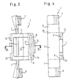
- the clip 1 shown in the drawings consists of the block 2 which is designed in the manner of a frame carrying the two resilient fingers 3 and 4 which, as shown in Figure 4, are constructed as upright arms.
- the resilient fingers 3 and 4 extend integrally as a continuous rib 5 over the block 2.
- Catching projections 6 and 7 are applied to the ends of the resilient fingers 3 and 4 and ascend stepwise in this case, further details of which will be given below in connection with Figure 1.
- the resilient fingers 3 and 4 and the rib 5 are connected to the block 2 in that the upright arms forming the resilient fingers 3 and 4 and the rib 5 pass integrally into the material of the block 2 at positions 8 and 9.
- the resilient fingers 3 and 4 are opposed by the abutment 10 which, together with the catching projections 6 and 7, serves to form a free gap (see Figures 1 and 3) serving to receive the longitudinal Flange 11 which is illustrated in Figure 1 and on which the clip 1 is to be applied. Further details of this will be given below.
- the abutment 10 is constructed integrally with the block 2 so that the material of the abutment 10 passes into the material of the block 2. Owing to the design of the abutment 10, which is triangular in cross section, (see Figure 3), the abutment 10 has considerable stability.
- the catching lugs 12 and 13 which serve to mount a decorative strip, for example the decorative strip 24 shown in Figure 1.
- the catching lugs 12 and 13 have a triangular cross section (see Figure 3) so that a resilient decorative strip can be pressed away over the catching lugs 12 and 13 and can then be secured by them.
- the ornamental strip 24 is also given inherent elasticity by the provision, behind it and toward the inner part of the block 2, of a recess 14 which enables the catching lug 12 to recede elastically toward the abutment 10.
- the connecting pieces 15 and 16 form elastic zones inside the block 2, which allow this yielding of the catching lug 12.
- the block 2 retains the stability required of it in that the recess 14 is held together toward the abutment 10 by the cross member 17.
- the clip 1 shown caught on the longitudinal flange 11 in Figure 1 lies with its abutment 10 on the side of the longitudinal flange 11 remote from the bend 20.
- a catching projection 6 is positioned behind the bend 20, allowing the resilient fingers 3 and 4 to be caught since they are provided with bevels 21 by means of which the resilient fingers 3 and 4 can recede when the clip 1 is pressed onto the longitudinal flange 11 with its bend 20, their design as upright arms assisting here.
- the resilient fingers adopt the position indicated in dot dash lines in Figure 2 until, they jump back substantially in their original position when catching is complete and engage behind the bend 20 with their catching projections 6 which ascend stepwise.
- the stepwise ascent of the catching projections 6 allows tolerances with respect to the position of the bend 20 to be compensated (see bend 20' indicated in dot dash lines).
- Figure 1 also shows how an ornamental strip 14 is caught onto the clip 1 applied to the longitudinal flange 11.
- the ornamental strip 14 jumps with its turned in borders 22 and 23 behind the outermost positions of the catching lugs 12 and 13 so that the ornamental strip 14 is held securely owing to its inherent elasticity and the elasticity of the fixing of the catching lug 12.
Landscapes
- Engineering & Computer Science (AREA)
- General Engineering & Computer Science (AREA)
- Mechanical Engineering (AREA)
- Connection Of Plates (AREA)
- Vehicle Interior And Exterior Ornaments, Soundproofing, And Insulation (AREA)
Applications Claiming Priority (2)
| Application Number | Priority Date | Filing Date | Title |
|---|---|---|---|
| DE9000563U DE9000563U1 (de) | 1990-01-19 | 1990-01-19 | An einem Längsflansch anzubringende Klammer zur Halterung von Bauteilen, insbesondere Zierleisten |
| DE9000563U | 1990-01-19 |
Publications (2)
| Publication Number | Publication Date |
|---|---|
| EP0437959A2 true EP0437959A2 (de) | 1991-07-24 |
| EP0437959A3 EP0437959A3 (en) | 1992-07-29 |
Family
ID=6850157
Family Applications (1)
| Application Number | Title | Priority Date | Filing Date |
|---|---|---|---|
| EP19900313965 Withdrawn EP0437959A3 (en) | 1990-01-19 | 1990-12-19 | Clip |
Country Status (4)
| Country | Link |
|---|---|
| US (1) | US5155887A (de) |
| EP (1) | EP0437959A3 (de) |
| JP (1) | JPH071308U (de) |
| DE (1) | DE9000563U1 (de) |
Cited By (2)
| Publication number | Priority date | Publication date | Assignee | Title |
|---|---|---|---|---|
| EP0489505A1 (de) * | 1990-11-28 | 1992-06-10 | Emhart Inc. | Metallischer Schweissbolzen und Kunststoffklammer |
| WO1996018044A1 (fr) * | 1994-12-09 | 1996-06-13 | Irgang Guenther | Dispositif d'assemblage rapide par clippage |
Families Citing this family (13)
| Publication number | Priority date | Publication date | Assignee | Title |
|---|---|---|---|---|
| JPH081285Y2 (ja) * | 1991-04-18 | 1996-01-17 | 株式会社ニフコ | モール取付用クリップ |
| FR2679846B1 (fr) * | 1991-07-31 | 1993-12-03 | Peugeot Automobiles | Dispositif de reglage du positionnement d'un pare-chocs de vehicule automobile. |
| DE4414905C2 (de) * | 1994-04-28 | 1997-07-10 | Daimler Benz Ag | Befestigungseinrichtung für ein Verkleidungsteil an einer Karosserieteilwandung |
| US5732450A (en) * | 1996-01-31 | 1998-03-31 | Motorola, Inc. | Resilient snap fitment member |
| GB2321884A (en) * | 1997-02-07 | 1998-08-12 | Standard Prod Ltd | Vehicle roof channel moulding |
| DE10360741B4 (de) * | 2003-12-23 | 2007-06-14 | Daimlerchrysler Ag | Befestigung einer Zierleiste in einem Dachgraben einer Fahrzeugkarosserie |
| DE102004005963B4 (de) * | 2004-02-06 | 2007-12-06 | Decoma (Germany) Gmbh | Befestigungselement |
| US7004537B2 (en) * | 2004-02-27 | 2006-02-28 | Sport Carriers, Inc. | Molding apparatus for vehicles and methods for use |
| DE102006039577B3 (de) * | 2006-08-23 | 2008-01-03 | A. Raymond Et Cie | Vorrichtung zum Halten einer Leiste in einem Kanal |
| US8020354B2 (en) * | 2008-01-30 | 2011-09-20 | Illinois Tools Works Inc. | Roof ditch molding retainer |
| DE102008048023B4 (de) | 2008-09-19 | 2011-04-28 | A. Raymond Et Cie | Vorrichtung zum Fixieren einer Leiste |
| DE102009050990B4 (de) * | 2009-10-28 | 2020-09-17 | Bayerische Motoren Werke Aktiengesellschaft | Flächiges Karosseriebauteil aus einem Kohlefaser-verstärkten Kunststoff |
| GB2533383A (en) * | 2014-12-18 | 2016-06-22 | Bentley Motors Ltd | Roof rail |
Family Cites Families (10)
| Publication number | Priority date | Publication date | Assignee | Title |
|---|---|---|---|---|
| US2188026A (en) * | 1935-11-02 | 1940-01-23 | William R Wiley | Clip |
| US3006444A (en) * | 1958-08-18 | 1961-10-31 | Gen Motors Corp | Clip |
| US2964814A (en) * | 1958-12-29 | 1960-12-20 | United Carr Fastener Corp | Fastener devices for securing a channel or like shape moulding strip to a support |
| US3120884A (en) * | 1960-09-26 | 1964-02-11 | United Carr Fastener Corp | Molding fastener |
| US3634991A (en) * | 1969-11-13 | 1972-01-18 | Gen Motors Corp | Molding retainer |
| US3977048A (en) * | 1975-09-15 | 1975-08-31 | Usm Corporation | Molding clips |
| US4135277A (en) * | 1976-05-25 | 1979-01-23 | Nifco, Inc. | Molding clip |
| DE7805870U1 (de) * | 1978-02-27 | 1978-10-19 | Tucker Metallwaren Gmbh, 6300 Lahn- Giessen | Klammer zur Halterung von Leisten, insbesondere Zierleisten |
| DE3331241C2 (de) * | 1983-08-30 | 1987-02-05 | TRW United-Carr GmbH, 6753 Enkenbach-Alsenborn | Halteclip aus Kunststoff |
| JPS6256809U (de) * | 1985-09-30 | 1987-04-08 |
-
1990
- 1990-01-19 DE DE9000563U patent/DE9000563U1/de not_active Expired - Lifetime
- 1990-12-19 EP EP19900313965 patent/EP0437959A3/en not_active Withdrawn
-
1991
- 1991-01-17 JP JP000970U patent/JPH071308U/ja active Pending
- 1991-01-17 US US07/642,347 patent/US5155887A/en not_active Expired - Fee Related
Cited By (3)
| Publication number | Priority date | Publication date | Assignee | Title |
|---|---|---|---|---|
| EP0489505A1 (de) * | 1990-11-28 | 1992-06-10 | Emhart Inc. | Metallischer Schweissbolzen und Kunststoffklammer |
| WO1996018044A1 (fr) * | 1994-12-09 | 1996-06-13 | Irgang Guenther | Dispositif d'assemblage rapide par clippage |
| FR2733803A1 (fr) * | 1994-12-09 | 1996-11-08 | Irgang Gunther | Dispositif d'assemblage rapide par clippage, ouvert sur deux cotes, realisable dans n'importe quelle longueur souhaitee, a effet autobloquant et a rattrapage de tolerances de positionnement |
Also Published As
| Publication number | Publication date |
|---|---|
| DE9000563U1 (de) | 1990-04-26 |
| EP0437959A3 (en) | 1992-07-29 |
| US5155887A (en) | 1992-10-20 |
| JPH071308U (ja) | 1995-01-10 |
Similar Documents
| Publication | Publication Date | Title |
|---|---|---|
| EP0437959A2 (de) | Clip | |
| EP0448270A1 (de) | Dichtungsstreifen für einen Scheibenlaufkanal | |
| CN101528514A (zh) | 雨刷片 | |
| JPH0715306Y2 (ja) | ワイヤハーネスプロテクタ | |
| JPH02124348A (ja) | 自動車のワイパ装置用のワイパブレード | |
| JP4132983B2 (ja) | クリップの取付構造 | |
| US7105748B2 (en) | Door module for a vehicle | |
| GB2238713A (en) | A windscreen wiper blade assembly | |
| KR970008120B1 (ko) | 엔진 마운트 부착용 스톱퍼 | |
| EP0167928B1 (de) | Klammer zum Befestigen von Fahrzeugfensterscheiben | |
| EP0881129A3 (de) | Mittel zur Befestigung einer Airbagabdeckung | |
| JP3427552B2 (ja) | ワイヤハーネス取付用バンド | |
| US20130058119A1 (en) | Vehicle room lamp | |
| US20060230586A1 (en) | Clip wtih corresponding clip housing | |
| US10737643B2 (en) | Engaging member | |
| JP2509930Y2 (ja) | 樹脂製バンパのハ―ネス固定構造 | |
| JP2006192978A (ja) | ルームミラー用ハーネスカバーの取り付け構造 | |
| JPH11321572A (ja) | ワイパ―ブレ―ドエレメントおよび保持クリップ | |
| JP3519821B2 (ja) | ベルトモールディング | |
| JPH04310423A (ja) | トリムパネルを支持パネルに取り付ける固定装置 | |
| KR970005403Y1 (ko) | 자동차 앞유리의 위치 조정용 클립 | |
| JPH071327Y2 (ja) | モール固定用クリップ | |
| JPS609107Y2 (ja) | 自動車用内張の取付装置 | |
| JPH0719912Y2 (ja) | 自動車の吊り天井 | |
| KR970005406Y1 (ko) | 자동차 앞유리의 부착구조 |
Legal Events
| Date | Code | Title | Description |
|---|---|---|---|
| PUAI | Public reference made under article 153(3) epc to a published international application that has entered the european phase |
Free format text: ORIGINAL CODE: 0009012 |
|
| AK | Designated contracting states |
Kind code of ref document: A2 Designated state(s): DE ES FR GB IT SE |
|
| PUAL | Search report despatched |
Free format text: ORIGINAL CODE: 0009013 |
|
| AK | Designated contracting states |
Kind code of ref document: A3 Designated state(s): DE ES FR GB IT SE |
|
| STAA | Information on the status of an ep patent application or granted ep patent |
Free format text: STATUS: THE APPLICATION IS DEEMED TO BE WITHDRAWN |
|
| 18D | Application deemed to be withdrawn |
Effective date: 19930130 |