EP0437962A2 - Drehkolbenpumpe - Google Patents
Drehkolbenpumpe Download PDFInfo
- Publication number
- EP0437962A2 EP0437962A2 EP90314055A EP90314055A EP0437962A2 EP 0437962 A2 EP0437962 A2 EP 0437962A2 EP 90314055 A EP90314055 A EP 90314055A EP 90314055 A EP90314055 A EP 90314055A EP 0437962 A2 EP0437962 A2 EP 0437962A2
- Authority
- EP
- European Patent Office
- Prior art keywords
- piston
- working chamber
- collar
- cylindrical
- suction
- Prior art date
- Legal status (The legal status is an assumption and is not a legal conclusion. Google has not performed a legal analysis and makes no representation as to the accuracy of the status listed.)
- Withdrawn
Links
- 238000005192 partition Methods 0.000 claims abstract description 26
- 230000002093 peripheral effect Effects 0.000 claims description 8
- 238000007789 sealing Methods 0.000 claims description 7
- 238000005086 pumping Methods 0.000 description 7
- 239000007788 liquid Substances 0.000 description 2
- 239000000126 substance Substances 0.000 description 2
- 230000000694 effects Effects 0.000 description 1
- 238000004519 manufacturing process Methods 0.000 description 1
Images


Classifications
-
- F—MECHANICAL ENGINEERING; LIGHTING; HEATING; WEAPONS; BLASTING
- F04—POSITIVE - DISPLACEMENT MACHINES FOR LIQUIDS; PUMPS FOR LIQUIDS OR ELASTIC FLUIDS
- F04C—ROTARY-PISTON, OR OSCILLATING-PISTON, POSITIVE-DISPLACEMENT MACHINES FOR LIQUIDS; ROTARY-PISTON, OR OSCILLATING-PISTON, POSITIVE-DISPLACEMENT PUMPS
- F04C2/00—Rotary-piston machines or pumps
- F04C2/30—Rotary-piston machines or pumps having the characteristics covered by two or more groups F04C2/02, F04C2/08, F04C2/22, F04C2/24 or having the characteristics covered by one of these groups together with some other type of movement between co-operating members
- F04C2/34—Rotary-piston machines or pumps having the characteristics covered by two or more groups F04C2/02, F04C2/08, F04C2/22, F04C2/24 or having the characteristics covered by one of these groups together with some other type of movement between co-operating members having the movement defined in groups F04C2/08 or F04C2/22 and relative reciprocation between the co-operating members
- F04C2/356—Rotary-piston machines or pumps having the characteristics covered by two or more groups F04C2/02, F04C2/08, F04C2/22, F04C2/24 or having the characteristics covered by one of these groups together with some other type of movement between co-operating members having the movement defined in groups F04C2/08 or F04C2/22 and relative reciprocation between the co-operating members with vanes reciprocating with respect to the outer member
- F04C2/3568—Rotary-piston machines or pumps having the characteristics covered by two or more groups F04C2/02, F04C2/08, F04C2/22, F04C2/24 or having the characteristics covered by one of these groups together with some other type of movement between co-operating members having the movement defined in groups F04C2/08 or F04C2/22 and relative reciprocation between the co-operating members with vanes reciprocating with respect to the outer member with axially movable vanes
Definitions
- the invention relates to a rotary pump comprising a rotary disc-shaped piston and a movable partition.
- the pump is particularly suitable for pumping liquid substances containing incompressible admixtures and biological liquors which cannot be pumped by means of orthodox pumps.
- the aim of the invention is to substantially mitigate some drawbacks of well-known pumps, such as relatively short life-time, limited piston revolution rate, and a questionable sealing of the sucking and discharge spaces from each other, which, as a rule, requires non-return valves.
- the working chamber receives a piston in the form of a short cylindrical body whose height corresponds to that of said cylindrical working chamber.
- a piston collar whose peripheral curve is an ellipse.
- the major axis of the latter is identical with the diagonal of axial section of said cylindrical working chamber while its minor axis is identical with the diameter of said chamber.
- the major axis of the ellipse includes with the axis of working chamber an angle of at most 30° which prevails also in contact points of the piston collar and the outer area of said cylindrical body.
- the pump working stroke is also characterized by said angle.
- a cylindrical sliding groove designed for receiving a movable cylindrical partition for separating the suction and the discharge space from each other.
- the inlet opening of suction duct is circular while the outlet suction opening is triangular, the shape of inner surface of the suction duct simulating the shape of piston collar.
- the discharge duct has a circular outlet discharge opening while the inlet discharge opening is of triangular configuration, the shape of inner surface of said discharge duct in the housing wall simulating the piston collar shape.
- the ducts are being opened and closed, due to piston collar revolution while in the movable cylindrical partition there is freely mounted a sealing ball with a recess allowing the passage for the piston collar.
- This passage depends upon the varying angle of turning of the piston collar, relative to the partition in a set of planes; thus the presence of said sealing ball makes it possible to build the piston collar in the form of a flat elliptical disc.
- a higher effect of the invention consists in a relatively simple pump structure which is free of any suction or discharge valves.
- the embodiment of the sealing partition together with the sealing ball enables a plain flat configuration of the piston collar to be used whereby claims laid on the manufacture thereof, in view of the hitherto applied pistons of more complicated shapes, are markedly reduced.
- the pump operates quite smoothly, ie without pressure impacts.
- the structure makes it possible to pump media containing even some minor incompressible objects, since the piston collar curve configuration and partition embodiment allow such media to be discharged without the piston being seized by such an incompressible object. It is why the pump of the invention is very suitable to be used for processing media of alimentary character as well as biotechnological liquid substances, since the pumping operation is very gentle.
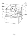
- the pump has a housing defined by a sidewall 1, which may be formed by two mutually opposite partial sidewalls, and two mutually opposite end walls, namely a front wall 3 and a back wall 2.
- the housing provides in its interior a working chamber 10 of a substantially cylindrical configuration.
- a cylindrical slide groove 16 for receiving a partition 8, the groove 16 being substantially parallel to the axis of the chamber 10.
- the slide groove 16 extends through the end walls 2 and 3 into boxes 15 for said partition 8.
- In the sidewall are provided at one side of the slide groove 16 the opening of a suction duct 4 and at the other side thereof the opening of a discharge duct 5. Both said openings are of a triangular configuration.
- the ducts 4 and 5 merge into respective flanges 11 and 12 which are attached to the housing walls.
- a suction conduit 13 in the flange 11 is of circular cross-section which gradually changes into a triangular one which is identical with the profile of the suction duct 4.
- a discharge conduit 14 in the flange 12 changes its circular cross-section to a triangular one corresponding to the cross-section of the discharge duct 5.
- the pump piston received in the working chamber 10 is constituted by a cylindrical body 6 and a piston collar 7 in the form of a flat elliptical disc which is situated obliquely on the cylindrical body 6.
- the collar 7 includes with the axis of the body 6 and of the working chamber 10 an angle of at most 30°.
- the peripheral curve of the piston collar 7 has the configuration of an ellipse whose major axis is identical with the diagonal of axial section of the cylindrical working chamber 10 ( Figure 4) while the minor axis thereof is identical with the diameter of said chamber 10 ( Figure 3).
- the curve intersecting the piston collar 7 and the cylindrical body 6 is also constituted by an ellipse whose major axis is identical with the diagonal of axial section of said cylindrical body 6.
- the piston collar 7 contacts in every point of its outer periphery the surface of the working chamber 10 ( Figure 6).
- Figure 6 In the axis of the cylindrical body 6 and in the two end walls 2 and 3 is provided an opening for mounting a driving shaft of the piston.
- the slide groove 16 receives slidably the movable cylindrical partition 8 in the middle of which a sealing ball 9 is freely mounted.
- the ball 9 has a recess forming a passage for the piston collar 7.
- the cylindrical piston body 6 together with the piston collar divide the working chamber 10 into two parts, each of which is in turn divided by the partition 8 in two parts so that four separate spaces are formed which revolve, owing to the rotation of the piston 6 with the collar 7, about the axis of the working chamber 10.
- the working chamber 10 assumes alternately the suction and discharge function, the partition 8 separating in each phase the discharge space.
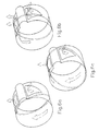
- Figures 6a, 6b and 6c and 7a, 7b and 7c are perspective views of the surface of the working chamber, showing the suction and the discharge openings. Dashed line indicates the peripheral curve of the piston collar 7. These Figures show also the surface of the slide groove 16. For the sake of clarity, the piston and the partition have been omitted.
- Figures 7a, 7b and 7c which correspond to Figures 6a, 6b and 6c, respectively, show the developed surface of the working chamber 10 together with peripheral curve of the piston collar 7 and the position of the partition 8.
- FIGs 6a and 7a show the first pumping phase.
- the piston collar 7 contacts the circular bases of the working chamber 10 at points B and D.
- the partition is in this phase in its left-hand extreme position.
- the suction duct is fully opened into the suction space in the right-hand portion of the working chamber while the discharge duct is fully opened into the discharge space in the right-hand portion of the working chamber.
- the two spaces are separated from each other by the partition 8 and the piston collar 7 at the point D (see Figure 7a).
- the suction has just ended, the suction duct has been closed and, due to the continuing turning of the piston, the discharge duct opened. At this instant, the suction space becomes the discharge one.
- FIGs 6b and 7b show the next pumping phase.
- the rotary piston has turned through 90° and the piston collar 7 has displaced the partition to its middle position.
- vacuum begins to be produced in the new suction space in the left-hand portion of the working chamber 10.
- the suction duct is opened into said space only partially and, as the piston turns, it is being further opened.
- the left-hand suction space is separated from the left-hand discharge space by the partition 8 and the piston collar 7 at the point B (see Figure 7b).
- the right-hand suction space is being gradually closed.
- the discharge duct has been opened into the left-hand discharge space and as the piston turns, it is being further opened.
- the discharge is being ended and the discharge duct, due to the rotation of the piston, is being closed.
- the shapes of the suction and discharge ducts exactly simulate the shape of peripheral curve of the piston collar. It is further apparent that the suction or vacuum spaces are being enlarged proportionally to the closing of the suction duct; similarly, the discharge spaces are being reduced in dependence upon the opening of the discharge duct. Thus the pump operation is absolutely continuous, ie free of impacts.
Landscapes
- Engineering & Computer Science (AREA)
- Mechanical Engineering (AREA)
- General Engineering & Computer Science (AREA)
- Reciprocating Pumps (AREA)
Applications Claiming Priority (2)
| Application Number | Priority Date | Filing Date | Title |
|---|---|---|---|
| CS90184A CS18490A3 (en) | 1990-01-15 | 1990-01-15 | Positive-displacement rotary sinusoidal pump |
| CS184/90 | 1990-01-15 |
Publications (2)
| Publication Number | Publication Date |
|---|---|
| EP0437962A2 true EP0437962A2 (de) | 1991-07-24 |
| EP0437962A3 EP0437962A3 (en) | 1992-01-15 |
Family
ID=5333555
Family Applications (1)
| Application Number | Title | Priority Date | Filing Date |
|---|---|---|---|
| EP19900314055 Withdrawn EP0437962A3 (en) | 1990-01-15 | 1990-12-20 | Rotary pump |
Country Status (2)
| Country | Link |
|---|---|
| EP (1) | EP0437962A3 (de) |
| CS (1) | CS18490A3 (de) |
Cited By (5)
| Publication number | Priority date | Publication date | Assignee | Title |
|---|---|---|---|---|
| DE4222429A1 (de) * | 1992-07-09 | 1994-01-20 | Pkl Verpackungssysteme Gmbh | Pumpe |
| KR100625207B1 (ko) | 2004-01-26 | 2006-09-20 | 현경열 | 유체 펌프 및 모터 |
| KR100679667B1 (ko) | 2005-12-16 | 2007-02-07 | 현경열 | 회전형 2단 압축기 |
| CN108087267A (zh) * | 2017-12-13 | 2018-05-29 | 杭州电子科技大学 | 一种具有轴向端面面密封结构转子 |
| CN111976471A (zh) * | 2020-08-09 | 2020-11-24 | 肇庆高新区伙伴汽车技术有限公司 | 一种提高新能源汽车性价比的方法及其自动挡汽车 |
Family Cites Families (5)
| Publication number | Priority date | Publication date | Assignee | Title |
|---|---|---|---|---|
| BE471573A (de) * | ||||
| GB191117366A (en) * | 1911-07-29 | 1912-07-25 | Pittler Universal Rotary Machi | Improvements in Rotary Pumps and similar Rotary Machines. |
| GB352526A (en) * | 1930-04-04 | 1931-07-06 | John James Owen | Wedge effect rotary pump |
| US2628566A (en) * | 1948-11-09 | 1953-02-17 | Berner Leo | Torque converter |
| US4093408A (en) * | 1976-12-03 | 1978-06-06 | Yoshichika Yamaguchi | Positive cam type compressor |
-
1990
- 1990-01-15 CS CS90184A patent/CS18490A3/cs unknown
- 1990-12-20 EP EP19900314055 patent/EP0437962A3/en not_active Withdrawn
Cited By (5)
| Publication number | Priority date | Publication date | Assignee | Title |
|---|---|---|---|---|
| DE4222429A1 (de) * | 1992-07-09 | 1994-01-20 | Pkl Verpackungssysteme Gmbh | Pumpe |
| KR100625207B1 (ko) | 2004-01-26 | 2006-09-20 | 현경열 | 유체 펌프 및 모터 |
| KR100679667B1 (ko) | 2005-12-16 | 2007-02-07 | 현경열 | 회전형 2단 압축기 |
| CN108087267A (zh) * | 2017-12-13 | 2018-05-29 | 杭州电子科技大学 | 一种具有轴向端面面密封结构转子 |
| CN111976471A (zh) * | 2020-08-09 | 2020-11-24 | 肇庆高新区伙伴汽车技术有限公司 | 一种提高新能源汽车性价比的方法及其自动挡汽车 |
Also Published As
| Publication number | Publication date |
|---|---|
| CS18490A3 (en) | 1992-05-13 |
| EP0437962A3 (en) | 1992-01-15 |
Similar Documents
| Publication | Publication Date | Title |
|---|---|---|
| JP2002501800A (ja) | 葉形(lobed)チャンバを備えた真空ポンプを用いた静粛な真空掃除機 | |
| EP0437962A2 (de) | Drehkolbenpumpe | |
| KR970008001B1 (ko) | 유체 압축기 | |
| US4008018A (en) | Rotary fluid displacement device having improved porting | |
| US4531899A (en) | Positive displacement rotary gas compressor pump | |
| EP3158196B1 (de) | Rotationsflüssigkeitspumpe | |
| US4004865A (en) | Pump with yieldable radial partitions and rotatable side plates | |
| CN111164311B (zh) | 流体用旋转活塞泵 | |
| US4099896A (en) | Rotary compressor | |
| JPH08277785A (ja) | ベーンポンプ | |
| KR20150104993A (ko) | 가변 사판식 압축기의 밸브어셈블리 | |
| EP1022464A2 (de) | Verdichterventil | |
| US20210372403A1 (en) | Fluid transfer device | |
| KR930007667Y1 (ko) | 진공 펌프 | |
| US4173438A (en) | Rotary piston device which displaces fluid in inner and outer variable volume chambers simultaneously | |
| EP0085248A1 (de) | Verdrängermaschine von Umlaufkolbentyp mit innerem Ausgleichsgewicht | |
| JPS6261798B2 (de) | ||
| JPS6345580Y2 (de) | ||
| JPH0648153Y2 (ja) | 偏心カム駆動の往復動ポンプ | |
| KR890002599Y1 (ko) | 로오타리 피스톤펌프 | |
| KR100469681B1 (ko) | 병렬구조의 용적식 펌프 | |
| EP3149332B1 (de) | Kreiselpumpe | |
| KR20040107541A (ko) | 유체펌프 | |
| JPH0219309B2 (de) | ||
| JPH0219308B2 (de) |
Legal Events
| Date | Code | Title | Description |
|---|---|---|---|
| PUAI | Public reference made under article 153(3) epc to a published international application that has entered the european phase |
Free format text: ORIGINAL CODE: 0009012 |
|
| AK | Designated contracting states |
Kind code of ref document: A2 Designated state(s): AT BE CH DE FR GB IT LI NL SE |
|
| PUAL | Search report despatched |
Free format text: ORIGINAL CODE: 0009013 |
|
| AK | Designated contracting states |
Kind code of ref document: A3 Designated state(s): AT BE CH DE FR GB IT LI NL SE |
|
| STAA | Information on the status of an ep patent application or granted ep patent |
Free format text: STATUS: THE APPLICATION IS DEEMED TO BE WITHDRAWN |
|
| 18D | Application deemed to be withdrawn |
Effective date: 19920716 |