EP0438003A1 - Hebelmechanismus zur Bewegungsübertragung und darin enthaltende Verriegelung - Google Patents
Hebelmechanismus zur Bewegungsübertragung und darin enthaltende Verriegelung Download PDFInfo
- Publication number
- EP0438003A1 EP0438003A1 EP90403802A EP90403802A EP0438003A1 EP 0438003 A1 EP0438003 A1 EP 0438003A1 EP 90403802 A EP90403802 A EP 90403802A EP 90403802 A EP90403802 A EP 90403802A EP 0438003 A1 EP0438003 A1 EP 0438003A1
- Authority
- EP
- European Patent Office
- Prior art keywords
- lever
- articulated
- point
- articulation
- extreme position
- Prior art date
- Legal status (The legal status is an assumption and is not a legal conclusion. Google has not performed a legal analysis and makes no representation as to the accuracy of the status listed.)
- Granted
Links
- 230000007246 mechanism Effects 0.000 title description 7
- 230000001131 transforming effect Effects 0.000 claims description 3
- 238000006073 displacement reaction Methods 0.000 description 6
- 230000002427 irreversible effect Effects 0.000 description 4
- 240000008042 Zea mays Species 0.000 description 3
- 230000009471 action Effects 0.000 description 2
- 230000006872 improvement Effects 0.000 description 2
- 230000006978 adaptation Effects 0.000 description 1
- 229910052782 aluminium Inorganic materials 0.000 description 1
- XAGFODPZIPBFFR-UHFFFAOYSA-N aluminium Chemical compound [Al] XAGFODPZIPBFFR-UHFFFAOYSA-N 0.000 description 1
- 230000008901 benefit Effects 0.000 description 1
- 230000000903 blocking effect Effects 0.000 description 1
- 239000003638 chemical reducing agent Substances 0.000 description 1
- 230000008878 coupling Effects 0.000 description 1
- 238000010168 coupling process Methods 0.000 description 1
- 238000005859 coupling reaction Methods 0.000 description 1
- 230000002349 favourable effect Effects 0.000 description 1
- 238000010348 incorporation Methods 0.000 description 1
- 229910052751 metal Inorganic materials 0.000 description 1
- 239000002184 metal Substances 0.000 description 1
- 230000004048 modification Effects 0.000 description 1
- 238000012986 modification Methods 0.000 description 1
- 238000005192 partition Methods 0.000 description 1
- 238000011144 upstream manufacturing Methods 0.000 description 1
Images


Classifications
-
- F—MECHANICAL ENGINEERING; LIGHTING; HEATING; WEAPONS; BLASTING
- F16—ENGINEERING ELEMENTS AND UNITS; GENERAL MEASURES FOR PRODUCING AND MAINTAINING EFFECTIVE FUNCTIONING OF MACHINES OR INSTALLATIONS; THERMAL INSULATION IN GENERAL
- F16H—GEARING
- F16H21/00—Gearings comprising primarily only links or levers, with or without slides
- F16H21/10—Gearings comprising primarily only links or levers, with or without slides all movement being in, or parallel to, a single plane
- F16H21/44—Gearings comprising primarily only links or levers, with or without slides all movement being in, or parallel to, a single plane for conveying or interconverting oscillating or reciprocating motions
-
- E—FIXED CONSTRUCTIONS
- E05—LOCKS; KEYS; WINDOW OR DOOR FITTINGS; SAFES
- E05C—BOLTS OR FASTENING DEVICES FOR WINGS, SPECIALLY FOR DOORS OR WINDOWS
- E05C9/00—Arrangements of simultaneously actuated bolts or other securing devices at well-separated positions on the same wing
- E05C9/18—Details of fastening means or of fixed retaining means for the ends of bars
- E05C9/1825—Fastening means
- E05C9/1833—Fastening means performing sliding movements
- E05C9/1841—Fastening means performing sliding movements perpendicular to actuating bar
-
- E—FIXED CONSTRUCTIONS
- E05—LOCKS; KEYS; WINDOW OR DOOR FITTINGS; SAFES
- E05B—LOCKS; ACCESSORIES THEREFOR; HANDCUFFS
- E05B47/00—Operating or controlling locks or other fastening devices by electric or magnetic means
- E05B47/0001—Operating or controlling locks or other fastening devices by electric or magnetic means with electric actuators; Constructional features thereof
- E05B2047/0014—Constructional features of actuators or power transmissions therefor
- E05B2047/0018—Details of actuator transmissions
- E05B2047/0024—Cams
- E05B2047/0025—Cams in the form of grooves
-
- E—FIXED CONSTRUCTIONS
- E05—LOCKS; KEYS; WINDOW OR DOOR FITTINGS; SAFES
- E05B—LOCKS; ACCESSORIES THEREFOR; HANDCUFFS
- E05B47/00—Operating or controlling locks or other fastening devices by electric or magnetic means
- E05B47/0001—Operating or controlling locks or other fastening devices by electric or magnetic means with electric actuators; Constructional features thereof
- E05B2047/0014—Constructional features of actuators or power transmissions therefor
- E05B2047/0018—Details of actuator transmissions
- E05B2047/0026—Clutches, couplings or braking arrangements
-
- E—FIXED CONSTRUCTIONS
- E05—LOCKS; KEYS; WINDOW OR DOOR FITTINGS; SAFES
- E05B—LOCKS; ACCESSORIES THEREFOR; HANDCUFFS
- E05B47/00—Operating or controlling locks or other fastening devices by electric or magnetic means
- E05B47/0001—Operating or controlling locks or other fastening devices by electric or magnetic means with electric actuators; Constructional features thereof
- E05B47/0012—Operating or controlling locks or other fastening devices by electric or magnetic means with electric actuators; Constructional features thereof with rotary electromotors
Definitions
- the subject of the invention is a mechanical device for transforming an alternating rectilinear displacement between two positions of a first part, such as a rod, into an alternating rectilinear displacement between two extreme positions of a second part arranged transversely to the first piece.
- the transverse arrangement mentioned above includes the strictly orthogonal arrangement of the first and the second part and, also, the relative arrangements of these parts which are not strictly orthogonal and which are here called transverse.
- the main object of the invention is to arrive at a new device capable, as explained above, of transforming a rectilinear movement of a first part into a rectilinear movement of a second part which can be arranged transversely and even exactly orthogonally.
- this device having, in a direction transverse to the alternating directions of displacement of the driving rod, a reduced bulk with a view to its incorporation into a current metal profile (frequently in spun aluminum) of a frame for an opening, for mounting a door, for example.
- a secondary object of the invention is to improve the device in question so that, when the second part has been placed in a determined position by a displacement of the first part, this second part is firmly locked in this determined position; in other words, the device then has a quality of total irreversibility when the second part has been placed in a determined position, so that any force then applied directly to this second part does not allow it to be displaced from this determined position to which it has been set.
- Another object of the invention is to achieve a device of the kind defined above having in addition a property of modification of the stroke of the second part with respect to the stroke of the first part, with a general overall size reduced so that this device can be used, among other various uses, in a lock for the operation of a bolt or several bolts of this lock from a first part, the bolt or bolts then being the second part designated above .
- the branch of the second lever between the second end and the top is arranged perpendicular to this second part.
- the points of articulation on the one hand of the second end of the second lever with the second part, on the other hand of the second end of the third lever on the external fixed point are on a straight line parallel to the rectilinear displacement of the second part, the obtuse angle of the branches of the second lever and the length of the third lever being such that the articulation of the second end of the second lever and the two articulations of the third lever are in alignment on said right when the second part is put in its second extreme position.
- the length of the branch of the second lever between the second end and the top of this lever and the distance between the joints of the ends of the third lever are chosen such that the value of the addition of these dimensions reduced by the distance separating the articulation of the second lever on the second part and the articulation of the third lever on the external fixed point is equal to the travel of the second part between its extreme positions.
- the operation of the first lever can be done directly by the first part or indirectly by a fourth lever with two branches relative to a pivot point of articulation, thus allowing the adaptation of the stroke of the first part to the desired stroke of the second part between the extreme positions of these parts.
- FIGS. 1 and 2 which, being simplified, make it possible to explain and understand more easily the constitution of the device of the invention.
- a general support 8 which can be any part on which the device is mounted; the latter is designated as a whole by the general reference M.
- the device M is used to transmit to a second part P2 which is, for example, guided in sliding in the support S, a movement in alternating directions in opposite directions indicated by a double arrow F1.
- This movement is derived from that of a first part which is not shown in Figures 1 and 2 for a reason which will be explained later.
- the device M comprises a first lever A which has a first end a1 and a second end a2; this lever A is arranged, in the main, in a direction orthogonal to the direction F1 of the movements of the second part P2.
- a second lever B is a bent lever with two branches, making an obtuse angle of 135 ° in this embodiment, starting from a vertex s and ending with a first end and a second end b2.
- the elbow of the second lever B is not compulsory but it is advantageous in that it promotes the compactness of the mechanism, in particular in the direction of reducing its overall dimensions in width transversely to the alternating directions of action of a rod. maneuver acting according to FT1 or FT0 in Figure 1.
- a third lever C has a first end c1 and a second end c2.
- the position of the fixed point 1 of articulation is chosen, in the present example, so close to the second articulated end b2 that a notch 2 has been made at the rear end of the second part P2 so that a hinge pin (not visible in Figures 1.2) can pass through the second end c2 to be received in the corresponding holes provided in the general support S to contain this axis and guide it in rotation.
- This arrangement is favorable to the compactness of the device M.
- the fixed point 1 of articulation could be further from the second end b2 of the second lever B and from the second part P2 when it occupies its first extreme position.
- the second branch of the lever B between its apex s and its second end b2 is substantially perpendicular to this second part P2. Due to the angle of 135 ° between the two branches of the second lever B, the second branch located between the apex s and the first end b1 is inclined by approximately 45 ° relative to the direction F1 of movement of the second part P2 .
- first lever A being articulated with the end b1 of the second branch defined above of the second lever B (in the state described above of the device), this first lever A is inclined, for example by an angle of 15 ° to 20 ° relative to the direction of the second branch. This angle varies, to a limited extent, depending on the length of the first lever A.
- the three points formed by the articulations of the vertex s, of the ends b2 and c2 are the vertices of a right triangle or little different from a right triangle.
- the second lever B tends to pivot under the action of the first lever A around the articulation of its vertex s, which shows at its second end b2 articulated on the second part P2 a force FT3 which pushes this second part P2 in a direction which moves it away from the fixed point 1.
- FIG. 2 shows the state of the device M after completion of the movements explained above.
- the triangle s, b2, c2 defined above is "flattened” as a result of the spacing of the sums b2 and c2 and the opening, until reaching 180 ° from the angle of the vertex s. Therefore, the second part P2 has slid in the general support S over a stroke which is equal to the increase in the new spacing of the joints b2, c2.
- the first end a1 of the first lever A has approached the second part P2 by a distance which corresponds to the movement of the second lever B.
- the blocking described above of the second part P2 in its second position is not necessary or is not desirable in all the circumstances of use of the device M. It is therefore possible to articulate the second end c2 of the third lever C around a fixed point 1 which is not on a line parallel to the direction F1 and passing through the articulation of the end b2 on the second part P2. In this case, the vertex angle s mentioned above does not have the value of 180 ° when the second part P2 is in its second position and the device ceases to be irreversible.
- the force FT1 does not necessarily have to be orthogonal to the direction F1 of the movements of the second part P2 for the device to function. It is possible that the force FT1 is exerted on the end a1 of the first lever A in an oblique direction relative to the direction F1. More generally, the force FT1 can therefore be a force transverse to the direction F1; its degree of obliquity is acceptable as long as the force FT1 results in a force FT2 which causes the third lever C to rotate in the appropriate direction around the fixed point 1.
- FIG. 1 As the device M in FIGS. 1 and 2 is irreversible as explained, the resetting of FIG. 1 is done only by the application on the end a1 of the first lever A of a force acting in direction opposite to that of force FT1.
- lever D shown in phantom in Figure 1 only.
- This lever D has a first end d1 by which it is articulated with the first end a1 of the first lever A and a second end d2 by which it can be maneuvered to pivot around a pivot 3 situated between its two ends d1, d2, and supported, for example, by general support S.
- This fourth lever D is disposed transversely in the assembly to the first lever A and the pivot 3 is placed at the desired location to adapt the travel of the end a1 of the first lever A (when the second part P2 is moved from a first extreme position to its second extreme position) when a force FT0 is applied to the second end d2 of the fourth lever D.
- the fourth lever D makes it possible to obtain the desired stroke of the second part P2 regardless of the stroke of the first part.
- Figures 3 to 5 relate to a real embodiment of the device M of the invention in which the fourth lever D is used to multiply the stroke of the first part and give a greater stroke to the second part.
- the first lever A is straight with a fork at its first end a1 to contain the first end d1 of the fourth lever D.
- the second lever B bent, is composed of two identical and parallel flat levers which contain between them the first end c1 of the third lever C; each of the two levers B is introduced by its second end b2 into a fairly wide recess 4 provided in the second part P2 from the rear end of the latter where the notch 2 is also located; each end b2 is articulated on the second part P2 using a respective axis 5, 5 ′ shown in broken lines in FIG. 5; thus the articulation of the second lever B is carried out using two half-axes which do not cross the second part P2.
- the third lever C is curved substantially in a semicircle in the same plane as a whole as the levers A, B; it develops between the two parallel levers B and also engages in the recess 4 to reach the notch 2 where its second end c2 is freely crossed by an axis 6 ( Figure 5).
- This axis 6 extends out of the notch 2 and it is contained in two holes 7 in extension of the general support S in which the second part P2 is guided in sliding.
- a screw 8 immobilizes the axis 6 in the general support S.
- Figures 3 and 4 also show that the general support S has a yoke 9 which is attached to it and fixed to be able to carry the axis 3 of the fourth lever D.
- the general support S is extended by a part which extends in the longitudinal direction of the first lever A and which serves to guide in sliding a first part P1.
- This part P1 is in fact a rod which is arranged in the general support S perpendicular to the second part P2.
- the first part P1 carries a lug 10.
- the fourth lever D is engaged in the two branches of the yoke 9 where it is mounted to pivot freely around the axis 3 and its second end d2 has an elongated slot 11, open to the outside, in which the lug 10 is engaged. The latter is free to slide in the slot elongated 11 and it moves the fourth lever D between two extreme positions when the rod which here constitutes the first part P1 is itself moved by sliding in the direction of its length, between two extreme positions. These extreme positions are visible respectively in FIG. 3 and in FIG. 4.
- the curved shape of the third lever C allows the latter to receive in its concavity the branch of the second lever B located between the vertex s of this lever B and its first end b1, at the same time as the second end a2 of the first lever A.
- This arrangement is necessary when it is desired that the joints b2, s, c2 are in alignment, as explained above, so that the device is irreversible, with the smallest possible footprint.
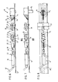
- FIGS. 6 to 8 relate to an example of practical use of the device of the invention making it possible to produce a lock with double electrical and mechanical control.
- All the parts of the lock are installed in a commercially available, elongated profile, in two parts of which only one part 11 is shown.
- This part 11 is used to carry the parts which are fixed there, the other part is analogous to a cover which encloses these parts.
- the elongated profile is designed to be fixed to a wall or a partition along an opening which can be closed by a movable panel. The latter, like a door for example, can be locked in the closed position by at least one bolt which is the second part P2 of the previous figures.
- This bolt, or second part P2 is operated by means of a device M of the invention from a sliding rod which is the first part P1 in Figures 3,4.
- This part P1 is slidably mounted in part 11 of the profile; it is guided in its movement by several transverse bridges 12, 13, 14, 15. These are notched to freely contain the first part P1 and are fixed by screws to the part 11 of the profile.
- the first part P1 acts by means of a fourth lever D carried by a yoke 9 in the same way as in FIGS. 3 and 4.
- the transverse bridges 12, 13, 14, 15 are used for mounting and / or fixing various parts, the role of which is to move, as desired, the first part P1 between two extreme positions to which the two extreme positions of total re-entry correspond and total exit from the second part or latch P2.
- the rod or first part P1 is placed in a direction exactly perpendicular to the direction of the bolt or second part P2.
- the volume available inside the closed profile is naturally limited in thickness and in width, hence the important advantage that the device M brings to transmit the movements of the first part to the second part.
- the lock of FIGS. 6 to 8 comprises an electric geared motor group 16 supported in overhang by the trigger guard 12 and able to be supplied with electric current by electric wires 17 which come out of the profile.
- the shaft of the geared motor group 16 crosses the trigger guard 12 and it is coupled by a flexible coupling 18 to a shaft 19 which passes between two micro-switches 20, which passes through the trigger guard 13 by which it is supported, and which carries a part 21 with a helical thread 22. This part is also supported by a shaft which engages in the trigger guard 14.
- the part 21 is generally cylindrical with a flat 23 which extends over its entire length devoid of helical thread.
- the first part P1 is provided with a button.
- maneuver 26 designed and arranged to be able to cooperate with the helical thread 22 when the part 21 is rotated by the electric geared motor group 16.
- the latter is capable, by turning, of moving the button 26 and the first part P1 between two extreme positions which are the same extreme positions defined above of the first part P1. At each of these extreme positions, the flat 23 is opposite the first part P1 and the button 26 is released from the helical thread 22.
- the microswitches 20 are arranged in correspondence with the extreme positions of the first part P1, to detect these positions and cause the motor-reduction unit 16 to stop at the desired time.
- the first part P1 is provided, in connection with the part 11 of the profile, with a braking means in position (not shown), such as a ball pushed by a spring and partially engaged in a corresponding housing at each of said extreme positions.
- a braking means in position (not shown), such as a ball pushed by a spring and partially engaged in a corresponding housing at each of said extreme positions.
- the trigger guard 15 carries the body 27 fixed with the aid of screws 28 of a cylinder lock 29 maneuverable in rotation using a key (not shown).
- the rotation of the cylinder 29 causes the displacement in rotation of a bit 30.
- a notch 31 in which the bit 30 can partially engage during its rotation and, then, cause the sliding in the longitudinal direction of the first part P1.
- the arrangement of the lock 29 is such that the bit 30 can engage in the notch 31 at each of the extreme positions of the first part P1 and move the latter to its other extreme position.
- the bit 30 is released from the notch 31; it is in the position of withdrawal of the key out of the lock in a recess 32 provided for this purpose in the body 27 as is usual.
- the first part P1 is completely uncoupled from the two means which make it possible to move it between its two extreme positions, that is to say on the one hand of the electric gearmotor group 16 and of the part 21 with its helical thread 22, on the other hand the key lock 29 with its bit 30.
- the movements of the first part P1 are transmitted by the device M to the second part P2 which is the bolt of the lock with double electrical / mechanical control which has just been described.
- the first part P1 is interrupted after its articulation in d2 with the fourth lever D. But it is possible, as indicated in phantom in FIG. 8, to provide an extension P1 'of the first part P1 , this extension bypassing the device and extending along part 11 of the profile to one or more other devices M each having a second part P2 serving as bolt. Several spaced apart bolts can therefore be operated simultaneously from each of the two electrical 16 and mechanical 29 maneuvering means.
- the extension can also be provided in the opposite direction, that is to say on the side of the geared motor group 16; such an extension is indicated by a dashed line P "1 in FIG. 8 for the operation of other bolts.
Landscapes
- Engineering & Computer Science (AREA)
- General Engineering & Computer Science (AREA)
- Mechanical Engineering (AREA)
- Lock And Its Accessories (AREA)
- Mechanical Control Devices (AREA)
- Transmission Devices (AREA)
Applications Claiming Priority (2)
| Application Number | Priority Date | Filing Date | Title |
|---|---|---|---|
| FR9000083 | 1990-01-05 | ||
| FR9000083A FR2656909A1 (fr) | 1990-01-05 | 1990-01-05 | Mecanisme transferant un deplacement d'une piece a une autre et serrure le comprenant. |
Publications (2)
| Publication Number | Publication Date |
|---|---|
| EP0438003A1 true EP0438003A1 (de) | 1991-07-24 |
| EP0438003B1 EP0438003B1 (de) | 1994-03-09 |
Family
ID=9392544
Family Applications (1)
| Application Number | Title | Priority Date | Filing Date |
|---|---|---|---|
| EP19900403802 Expired - Lifetime EP0438003B1 (de) | 1990-01-05 | 1990-12-28 | Hebelmechanismus zur Bewegungsübertragung und darin enthaltende Verriegelung |
Country Status (3)
| Country | Link |
|---|---|
| EP (1) | EP0438003B1 (de) |
| DE (1) | DE69007276D1 (de) |
| FR (1) | FR2656909A1 (de) |
Families Citing this family (2)
| Publication number | Priority date | Publication date | Assignee | Title |
|---|---|---|---|---|
| FR2816977B1 (fr) | 2000-11-22 | 2003-07-25 | Gerard Charles | Serrure a commande electrique |
| FR2944826B1 (fr) * | 2009-04-24 | 2011-05-27 | Gerard Charles | Serrure a pene coulant verrouillable par genouillere |
Citations (6)
| Publication number | Priority date | Publication date | Assignee | Title |
|---|---|---|---|---|
| FR340378A (fr) * | 1904-02-11 | 1904-07-05 | Georges Albin Beligard | Perfectionnements aux fermetures de portes |
| GB286515A (en) * | 1927-05-19 | 1928-03-08 | Herbert Edwin Newton | An improved fastening for doors, windows and like purposes |
| FR2091071A5 (de) * | 1970-05-04 | 1972-01-14 | Westinghouse Electric Corp | |
| GB2124320A (en) * | 1982-07-19 | 1984-02-15 | John Henry Brems | Linkage mechanism |
| FR2536108A1 (fr) * | 1982-11-17 | 1984-05-18 | Lambert Christian | Serrure de securite pour porte principale d'un local, tel qu'un appartement |
| GB2218729A (en) * | 1988-05-18 | 1989-11-22 | Ohi Seisakusho Co Ltd | Electric actuator for door lock |
-
1990
- 1990-01-05 FR FR9000083A patent/FR2656909A1/fr active Granted
- 1990-12-28 EP EP19900403802 patent/EP0438003B1/de not_active Expired - Lifetime
- 1990-12-28 DE DE90403802T patent/DE69007276D1/de not_active Expired - Lifetime
Patent Citations (6)
| Publication number | Priority date | Publication date | Assignee | Title |
|---|---|---|---|---|
| FR340378A (fr) * | 1904-02-11 | 1904-07-05 | Georges Albin Beligard | Perfectionnements aux fermetures de portes |
| GB286515A (en) * | 1927-05-19 | 1928-03-08 | Herbert Edwin Newton | An improved fastening for doors, windows and like purposes |
| FR2091071A5 (de) * | 1970-05-04 | 1972-01-14 | Westinghouse Electric Corp | |
| GB2124320A (en) * | 1982-07-19 | 1984-02-15 | John Henry Brems | Linkage mechanism |
| FR2536108A1 (fr) * | 1982-11-17 | 1984-05-18 | Lambert Christian | Serrure de securite pour porte principale d'un local, tel qu'un appartement |
| GB2218729A (en) * | 1988-05-18 | 1989-11-22 | Ohi Seisakusho Co Ltd | Electric actuator for door lock |
Also Published As
| Publication number | Publication date |
|---|---|
| FR2656909A1 (fr) | 1991-07-12 |
| EP0438003B1 (de) | 1994-03-09 |
| DE69007276D1 (de) | 1994-04-14 |
| FR2656909B1 (de) | 1995-02-10 |
Similar Documents
| Publication | Publication Date | Title |
|---|---|---|
| EP0593371B1 (de) | Antrieb für einen Dreistellungsschalter | |
| EP0179002B1 (de) | Einrichtung zum automatischen Schliessen, sowie zum Offenhalten von Türen | |
| WO2019238476A1 (fr) | Poignée de porte affleurante et son procédé de fonctionnement | |
| FR2624905A1 (fr) | Verrou plat pour relier deux elements | |
| FR2865492A1 (fr) | Ensemble de verrouillage, notamment d'un element mobile de fermeture, et combinaison l'utilisant | |
| FR2673744A1 (fr) | Dispositif de guidage de pieces de monnaie. | |
| EP0404609B1 (de) | Türschloss und -beschlag für Panikfälle | |
| EP0438003B1 (de) | Hebelmechanismus zur Bewegungsübertragung und darin enthaltende Verriegelung | |
| FR2816977A1 (fr) | Serrure a commande electrique | |
| EP1291479B1 (de) | Schloss mit Universalaufstellung | |
| FR2660689A1 (fr) | Ensemble de manóoeuvre pour verrou de second battant de porte. | |
| FR2861789A1 (fr) | Serrure anti-panique multipoint reversible | |
| FR2628261A1 (fr) | Disjoncteur a mecanisme a franchissement de point mort | |
| FR2769037A1 (fr) | Dispositif de verrouillage comportant un doigt de transmission commande par came | |
| EP1649478B1 (de) | Dreheingriffs-verriegelungsmechanismus für automatische sicherheitsabtrennung | |
| EP0241396B1 (de) | Automatischer Treibstangenverschluss mit Doppelaktion | |
| FR2650323A1 (fr) | Poignee rotative a pouvoir de deverrouillage | |
| EP0354107B1 (de) | Befestigungsvorrichtung zum schnellen Andocken und Lösen einer Struktur | |
| FR2645578A1 (fr) | Serrure pour portes a cran d'arret | |
| FR2812124A1 (fr) | Sectionneur a couteau avec un systeme de blocage par passage de point mort | |
| FR3066215B1 (fr) | Dispositif de deverrouillage d'un ouvrant | |
| EP3588526B1 (de) | Sicherungshalterung | |
| FR2944826A1 (fr) | Serrure a pene coulant verrouillable par genouillere | |
| FR2524276A1 (fr) | Dispositif d'ouverture d'un bagage muni d'une poignee pivotante | |
| FR2646873A1 (fr) | Dispositif de verrouillage de securite pour fenetres |
Legal Events
| Date | Code | Title | Description |
|---|---|---|---|
| PUAI | Public reference made under article 153(3) epc to a published international application that has entered the european phase |
Free format text: ORIGINAL CODE: 0009012 |
|
| 17P | Request for examination filed |
Effective date: 19910103 |
|
| AK | Designated contracting states |
Kind code of ref document: A1 Designated state(s): BE CH DE ES GB IT LI NL |
|
| 17Q | First examination report despatched |
Effective date: 19920730 |
|
| GRAA | (expected) grant |
Free format text: ORIGINAL CODE: 0009210 |
|
| AK | Designated contracting states |
Kind code of ref document: B1 Designated state(s): BE CH DE ES GB IT LI NL |
|
| PG25 | Lapsed in a contracting state [announced via postgrant information from national office to epo] |
Ref country code: IT Free format text: LAPSE BECAUSE OF FAILURE TO SUBMIT A TRANSLATION OF THE DESCRIPTION OR TO PAY THE FEE WITHIN THE PRE;WARNING: LAPSES OF ITALIAN PATENTS WITH EFFECTIVE DATE BEFORE 2007 MAY HAVE OCCURRED AT ANY TIME BEFORE 2007. THE CORRECT EFFECTIVE DATE MAY BE DIFFERENT FROM THE ONE RECORDED.SCRIBED TIME-LIMIT Effective date: 19940309 Ref country code: DE Effective date: 19940309 Ref country code: ES Free format text: THE PATENT HAS BEEN ANNULLED BY A DECISION OF A NATIONAL AUTHORITY Effective date: 19940309 Ref country code: GB Effective date: 19940309 Ref country code: NL Effective date: 19940309 |
|
| REF | Corresponds to: |
Ref document number: 69007276 Country of ref document: DE Date of ref document: 19940414 |
|
| NLV1 | Nl: lapsed or annulled due to failure to fulfill the requirements of art. 29p and 29m of the patents act | ||
| GBV | Gb: ep patent (uk) treated as always having been void in accordance with gb section 77(7)/1977 [no translation filed] |
Effective date: 19940309 |
|
| PG25 | Lapsed in a contracting state [announced via postgrant information from national office to epo] |
Ref country code: CH Effective date: 19941231 Ref country code: BE Effective date: 19941231 Ref country code: LI Effective date: 19941231 |
|
| PLBE | No opposition filed within time limit |
Free format text: ORIGINAL CODE: 0009261 |
|
| STAA | Information on the status of an ep patent application or granted ep patent |
Free format text: STATUS: NO OPPOSITION FILED WITHIN TIME LIMIT |
|
| 26N | No opposition filed | ||
| BERE | Be: lapsed |
Owner name: CHARLES GERARD Effective date: 19941231 |
|
| REG | Reference to a national code |
Ref country code: CH Ref legal event code: PL |