EP0438014A2 - Komplexkonstruktion für Elektronik von Zentrale mit Einheiten - Google Patents
Komplexkonstruktion für Elektronik von Zentrale mit Einheiten Download PDFInfo
- Publication number
- EP0438014A2 EP0438014A2 EP90480193A EP90480193A EP0438014A2 EP 0438014 A2 EP0438014 A2 EP 0438014A2 EP 90480193 A EP90480193 A EP 90480193A EP 90480193 A EP90480193 A EP 90480193A EP 0438014 A2 EP0438014 A2 EP 0438014A2
- Authority
- EP
- European Patent Office
- Prior art keywords
- complex
- cages
- logic elements
- enclosure
- side plate
- Prior art date
- Legal status (The legal status is an assumption and is not a legal conclusion. Google has not performed a legal analysis and makes no representation as to the accuracy of the status listed.)
- Granted
Links
- 238000010276 construction Methods 0.000 title description 8
- 239000002184 metal Substances 0.000 claims description 6
- 239000007787 solid Substances 0.000 claims description 2
- 238000002045 capillary electrochromatography Methods 0.000 description 2
- 208000015636 celiac disease-epilepsy-cerebral calcification syndrome Diseases 0.000 description 2
- 238000004519 manufacturing process Methods 0.000 description 2
- 238000000034 method Methods 0.000 description 2
- 230000035939 shock Effects 0.000 description 2
- 230000000712 assembly Effects 0.000 description 1
- 238000000429 assembly Methods 0.000 description 1
- 238000001816 cooling Methods 0.000 description 1
- 230000009977 dual effect Effects 0.000 description 1
- 239000000463 material Substances 0.000 description 1
- 230000013011 mating Effects 0.000 description 1
- 230000002441 reversible effect Effects 0.000 description 1
Images

Classifications
-
- H—ELECTRICITY
- H05—ELECTRIC TECHNIQUES NOT OTHERWISE PROVIDED FOR
- H05K—PRINTED CIRCUITS; CASINGS OR CONSTRUCTIONAL DETAILS OF ELECTRIC APPARATUS; MANUFACTURE OF ASSEMBLAGES OF ELECTRICAL COMPONENTS
- H05K7/00—Constructional details common to different types of electric apparatus
- H05K7/14—Mounting supporting structure in casing or on frame or rack
- H05K7/1422—Printed circuit boards receptacles, e.g. stacked structures, electronic circuit modules or box like frames
- H05K7/1424—Card cages
Definitions
- This invention relates generally to enclosures for containing and supporting logic elements and ancillary equipment for computing systems and, more particularly, to a central electronics complex (CEC) for electronic or computer components that directly receives a plurality of logic elements and other components, e.g., blowers or other ancillary components, wherein the enclosure itself is the primary structural element.
- CEC central electronics complex
- CEC central electronics complex
- An enclosure or mounting container is the primary structural element and that enclosure contains an independently constructed or formed logic cage and other hardware which might include blower assemblies, plenums, or other ancillary equipment.
- the typically constructed CEC is not very flexible.
- the requirement that different ancillary components be used as computing systems evolve means that the separate multi-part enclosure, as the primary structural element of a CEC, must undergo frequent significant redesign which in turn results in increased part numbers and additional tooling costs.
- the ability to be used in different computing systems or to be attractively covered to act as a stand alone unit is limited because it is difficult to design multiple mounting configurations for the enclosure. Differing mounts and different required equipment typically require a redesign of the basic enclosure, as well as additional parts.
- Using a separate multi-part enclosure for the basic structural element of a CEC results in increased weight causing shock and vibration concerns in addition to increased handling difficulty. Additionally, the separate multi-part enclosure is usually quite complex as a result of required ancillary equipment; this usually precludes assembling the CEC at the point of use.
- US-A 4.356.531 discloses a computer housing which has walls that form a cage for receiving cards and a fan module.
- the housing includes jig means for precise assembly of the walls and the walls are adapted to receive modules.
- the housing includes mechanical interconnection and the sidewalls are reversible.
- US-A 4.672.509 discloses an air cooling assembly in an electronic system enclosure wherein a cabinet with sides and a backplane is provided. Upper and lower racks, connected by screws through the sides of the cabinet, are provided for supporting a plurality of logic modules. A method of attaching the top and bottom plenum and/or support members is also disclosed.
- the present invention is directed to and in large part solves the problems discussed above.
- An enclosure is provided for containing the logic elements and ancillary components for computing systems.
- the enclosure is a unitized central electronics enclosure (CEC) wherein the primary structural element is the enclosure or cage for the logic elements.
- This enclosure or logic cage includes unitary side plates, a double-sided backplane and top and bottom guides.
- the integrated structural and enclosure functions accommodate both the structural needs of a CEC, as well as containing and supporting the logic elements and ancillary equipment.
- Yet another object of the present invention is to provide a CEC which is resistant to stress, shock and the vibration in shipping, handling and operational situations.
- Advantages of the CEC of the present invention are that it is substantially less complex than prior art enclosures, it is more flexible in terms of changing or adding items of ancillary equipment and simplicity of the construction permits the CEC to be constructed and tested away from the original in-plant manufacturing site.
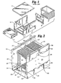
- FIG. 1 is an exploded perspective view of a prior art central electronics complex.
- FIG. 2 is a perspective view of the central electronics complex of the present invention.
- FIG. 3 is an exploded perspective view of the central electronics complex of the present invention.
- FIG. 4 is a perspective view of a side plate used in constructing the central electronics complex of the present invention.
- FIG. 1 shows a typically constructed prior art central electronics complex (CEC).
- the CEC is made up of an enclosure 2 having an enclosure cover 3.
- a logic cage 4 is mounted in enclosure 2.
- the enclosure 2 is designed to support and contain a blower assembly 6 and a plenum 8.
- Tabs 10 are provided for affixing the central enclosure to a rack or other mounting system (not shown).
- the enclosure 2 is the primary structural element and the major mechanical interface to the rest of the computing system, as well as between the various components identified herein above.
- FIGS. 2 and 3 depict the unitized central electronics complex (CEC) of the present invention.
- the CEC is indicated generally at 20 and includes logic cages 22, 23.
- the basic structural element of the present invention is side plate 24, 25.
- the side plates 24, 25 are provided with flanges 26 which are integrally formed and are provided to mount the CEC 20 in a typical EIA rack or other mounting system.
- the side plates 24, 25 have alignment apertures 28 and may be provided with additional apertures 38 for conventional fastening means.
- side plates 24, 25 are each formed of single pieces of sheet metal (see FIG. 4) and are mirror images of each other. This represents a substantial improvement over the prior art in terms of both cost savings and ease of assembly. Also, overall CEC 20 rigidity and tolerance control are improved.
- the CEC 20 of the present invention includes top and bottom guides 29, 30 which may be cast or may be formed by other suitable material or processes.
- the guides 29, 30 are planar and each has an arrangement of many generally rectangular openings 27.
- Guide slots 31 are provided for guiding and supporting logic elements 33 within the sub-cages 22, 23. It should be understood that the logic elements 33 have solid sides 35 and on their top and bottom edges have openings (not shown) which line up with the openings 27 on the guides 29, 30 when the elements 33 are fully inserted in sub-cages 22, 23.
- the guides 29, 30 are provided with alignment tabs 32.
- FIG. 2 the alignment of the guides 29, 30, parts 34 and 36 and side plates 24, 25 can be seen.
- the sub-cages 22, 23 share a common double-sided backplane assembly 46, described in greater detail in the European Patent application No. (Inventors : C.J. Aug, W.J. Casanova, W.D. Corfits et al) entitled DOUBLE-SIDED BACKPLANE ASSEMBLY, and filed concurrently with the present application.
- the backplane assembly 46 has a front side 45 and a back side 47 which face sub-cage 22, 23, respectively. Each side 45, 47 has connectors 52 so that logic elements 33 may be connected to both sides 45, 47.
- the backplane assembly 46 is mounted between the sub-cages 22, 23 by attaching it with conventional attachment means (not shown) to the guides 29, 30 along integral bars 48. Additionally, the backplane assembly 46 may be positioned or secured at side plates 24, 25 by parallel, vertical mounting gussets 49.
- Sheet metal adjuncts 34, 36 of low complexity are provided for mounting or attaching ancillary pieces of equipment as required.
- the sheet metal adjuncts 34, 36 may be used to integrate a blower assembly 51 into the CEC 20 or to form the top and bottom enclosing walls for a CEC if required by a specific function.
- the alignment of sheet metal adjuncts 34, 36 is accomplished by abutting specific edges of apertures 60, 61 to the mating surfaces of guide 29, 30 of tabs 32.
- the CEC 20 of the present invention is a double-sided or dual CEC. That is, the CEC 20 provides a double-sided enclosure made up of sub-cages 22, 23. The side plates 24, 25 extend for the length of both sub-cages 22, 23. This substantially improves the cage 22 to cage 23 alignment as well as the overall rigidity and resistance to vibration exhibited by the CEC 20. Additionally, the CEC 20 is easily adapted to a variety of uses and configurations simply by using different adjuncts 34, 36; the CEC 20 does not have to be fundamentally redesigned to be used with various ancillary equipment.
Landscapes
- Engineering & Computer Science (AREA)
- Microelectronics & Electronic Packaging (AREA)
- Mounting Of Printed Circuit Boards And The Like (AREA)
- Casings For Electric Apparatus (AREA)
Applications Claiming Priority (2)
| Application Number | Priority Date | Filing Date | Title |
|---|---|---|---|
| US07/467,594 US4984133A (en) | 1990-01-19 | 1990-01-19 | Unitized central electronics complex construction |
| US467594 | 1990-01-19 |
Publications (3)
| Publication Number | Publication Date |
|---|---|
| EP0438014A2 true EP0438014A2 (de) | 1991-07-24 |
| EP0438014A3 EP0438014A3 (en) | 1992-09-09 |
| EP0438014B1 EP0438014B1 (de) | 1994-09-07 |
Family
ID=23856324
Family Applications (1)
| Application Number | Title | Priority Date | Filing Date |
|---|---|---|---|
| EP90480193A Expired - Lifetime EP0438014B1 (de) | 1990-01-19 | 1990-11-27 | Komplexkonstruktion für Elektronik von Zentrale mit Einheiten |
Country Status (5)
| Country | Link |
|---|---|
| US (1) | US4984133A (de) |
| EP (1) | EP0438014B1 (de) |
| JP (1) | JPH07105606B2 (de) |
| BR (1) | BR9006653A (de) |
| DE (1) | DE69012305T2 (de) |
Cited By (5)
| Publication number | Priority date | Publication date | Assignee | Title |
|---|---|---|---|---|
| EP0464658A3 (en) * | 1990-07-03 | 1992-09-30 | International Business Machines Corporation | Enclosure for electronic subsystems in a data processing system |
| EP0581139A1 (de) * | 1992-07-25 | 1994-02-02 | ICOS Gesellschaft für Industrielle Communications Systeme mbH | Platinenanordnung für Computer od.dgl. |
| EP0685989A1 (de) * | 1994-05-30 | 1995-12-06 | BULL HN INFORMATION SYSTEMS ITALIA S.p.A. | Gestell für Computer mit einem modularen und vernieteten Aufbau |
| CN1054021C (zh) * | 1995-02-14 | 2000-06-28 | 克尼尔电子机械有限公司 | 结构系统 |
| GB2388475A (en) * | 2002-05-06 | 2003-11-12 | Hewlett Packard Co | System for supporting card guides and a backplane |
Families Citing this family (15)
| Publication number | Priority date | Publication date | Assignee | Title |
|---|---|---|---|---|
| US5214572A (en) * | 1991-08-21 | 1993-05-25 | International Business Machines Corporation | One-piece electronic cage |
| US5319520A (en) * | 1991-11-26 | 1994-06-07 | Kabushiki Kaisha Toshiba | Electronic equipment assembly of tiered type |
| US5394305A (en) * | 1993-12-23 | 1995-02-28 | Charles Industries, Ltd. | Card Cages for electronic modules |
| US6324065B1 (en) | 1999-03-31 | 2001-11-27 | Emc Corporation | Stiffener for a printed circuit board |
| US6325472B1 (en) | 1999-03-31 | 2001-12-04 | Emc Corporation | Fastening device for a printed circuit board |
| US6323423B1 (en) * | 1999-03-31 | 2001-11-27 | Emc Corporation | Housing for interconnected printed circuit boards |
| US6285563B1 (en) * | 1999-03-31 | 2001-09-04 | Emc Corporation | Support bracket for a printed circuit board connectable to daughter boards |
| US7310915B2 (en) | 2000-09-22 | 2007-12-25 | Tower Solutions, Llc | Retractable column and method of forming |
| US6646868B2 (en) * | 2001-06-04 | 2003-11-11 | Sun Microsystems, Inc. | Computer bus rack having an increased density of card slots |
| USD484508S1 (en) | 2002-11-27 | 2003-12-30 | International Business Machines Corporation | Server blade enclosure base |
| WO2004094790A2 (en) | 2003-04-17 | 2004-11-04 | Tower Solutions, Llc | Extendable/retractable support column |
| US7512854B2 (en) * | 2005-02-24 | 2009-03-31 | International Business Machines Corporation | Method and apparatus for testing, characterizing and monitoring a chip interface using a second data path |
| JP4361033B2 (ja) * | 2005-04-27 | 2009-11-11 | 株式会社日立製作所 | ディスクアレイ装置 |
| EP2633221A4 (de) | 2010-10-29 | 2018-02-14 | Tower Solutions, LLC | Aus- und einziehbare stützsäule |
| US10920444B2 (en) | 2018-03-22 | 2021-02-16 | Tower Solutions, Llc | Mobile tower for transportation and remote deployment |
Family Cites Families (12)
| Publication number | Priority date | Publication date | Assignee | Title |
|---|---|---|---|---|
| US3191097A (en) * | 1958-08-19 | 1965-06-22 | Commissariat Energie Atomique | Interchangeable chassis slides for carrying electronic equipment |
| US3184645A (en) * | 1960-03-24 | 1965-05-18 | Cutler Hammer Inc | Electrical circuit assembly |
| FR1504811A (fr) * | 1966-08-22 | 1967-12-08 | R E L App Electr Sa | Charnière démontable |
| US3733523A (en) * | 1972-02-11 | 1973-05-15 | Ampex | Electronic circuit card cage |
| JPS51104567A (en) * | 1975-03-11 | 1976-09-16 | Mitsubishi Electric Corp | Keisankiniokeru purintokaadotoritsukeho |
| US4232356A (en) * | 1979-02-07 | 1980-11-04 | Burroughs Corporation | Logic card frame |
| CA1164578A (en) * | 1980-10-24 | 1984-03-27 | Yoshihiro Takahashi | Shelf unit for electronic communication devices |
| JPS5853894A (ja) * | 1981-09-25 | 1983-03-30 | 日本電気株式会社 | 電子パツケ−ジ実装構造 |
| JPS60245298A (ja) * | 1984-05-21 | 1985-12-05 | 松下電器産業株式会社 | プリント基板収容装置 |
| JPS6197894U (de) * | 1984-12-04 | 1986-06-23 | ||
| US4876630A (en) * | 1987-06-22 | 1989-10-24 | Reliance Comm/Tec Corporation | Mid-plane board and assembly therefor |
| US4922125A (en) * | 1988-03-17 | 1990-05-01 | International Business Machines Corporation | System cable assembly and component packaging |
-
1990
- 1990-01-19 US US07/467,594 patent/US4984133A/en not_active Expired - Fee Related
- 1990-11-27 DE DE69012305T patent/DE69012305T2/de not_active Expired - Fee Related
- 1990-11-27 EP EP90480193A patent/EP0438014B1/de not_active Expired - Lifetime
- 1990-11-30 JP JP2341174A patent/JPH07105606B2/ja not_active Expired - Lifetime
- 1990-12-28 BR BR909006653A patent/BR9006653A/pt not_active Application Discontinuation
Cited By (8)
| Publication number | Priority date | Publication date | Assignee | Title |
|---|---|---|---|---|
| EP0464658A3 (en) * | 1990-07-03 | 1992-09-30 | International Business Machines Corporation | Enclosure for electronic subsystems in a data processing system |
| EP0581139A1 (de) * | 1992-07-25 | 1994-02-02 | ICOS Gesellschaft für Industrielle Communications Systeme mbH | Platinenanordnung für Computer od.dgl. |
| EP0685989A1 (de) * | 1994-05-30 | 1995-12-06 | BULL HN INFORMATION SYSTEMS ITALIA S.p.A. | Gestell für Computer mit einem modularen und vernieteten Aufbau |
| US5590938A (en) * | 1994-05-30 | 1997-01-07 | Bull Hn Information Systems Italia S.P.A. | Computer frame of riveted modular construction |
| CN1054021C (zh) * | 1995-02-14 | 2000-06-28 | 克尼尔电子机械有限公司 | 结构系统 |
| GB2388475A (en) * | 2002-05-06 | 2003-11-12 | Hewlett Packard Co | System for supporting card guides and a backplane |
| GB2388475B (en) * | 2002-05-06 | 2005-10-26 | Hewlett Packard Co | A system for supporting card guides and a backplane |
| US7007809B2 (en) | 2002-05-06 | 2006-03-07 | Hewlett-Packard Development Company, L.P. | System for supporting a backplane between card cages |
Also Published As
| Publication number | Publication date |
|---|---|
| JPH03222499A (ja) | 1991-10-01 |
| BR9006653A (pt) | 1991-10-01 |
| JPH07105606B2 (ja) | 1995-11-13 |
| DE69012305D1 (de) | 1994-10-13 |
| EP0438014B1 (de) | 1994-09-07 |
| EP0438014A3 (en) | 1992-09-09 |
| DE69012305T2 (de) | 1995-03-30 |
| US4984133A (en) | 1991-01-08 |
Similar Documents
| Publication | Publication Date | Title |
|---|---|---|
| EP0438014B1 (de) | Komplexkonstruktion für Elektronik von Zentrale mit Einheiten | |
| US5031075A (en) | Double-sided logic cage | |
| EP0438012B1 (de) | Anordnung für doppelseitige Rückwand | |
| US4699270A (en) | Modular packaging system | |
| US5557506A (en) | Expandable data processing chassis and method of assembly thereof | |
| US6049449A (en) | Computer with modular removable card cage | |
| US4748540A (en) | Compact packaging of electronic equipment within a small profile enclosure | |
| US5503472A (en) | Method and apparatus for assembly of a multi-disk pack unit | |
| US5214572A (en) | One-piece electronic cage | |
| US4669616A (en) | Rack for accommodating industrial electronic components | |
| EP0132152A2 (de) | Modulares Computer-System | |
| US5172306A (en) | Adaptive card mounting system | |
| US6434018B1 (en) | Rack mount system for pluggable computer modules | |
| US6219235B1 (en) | Electronic assembly for standard rack enclosures | |
| US20020067601A1 (en) | Method and apparatus for mounting electronic components within a housing | |
| US7239523B1 (en) | Electronic assembly with modular midplane | |
| US5224020A (en) | Electronic apparatus having modular front and back functional units and electrical distribution unit including a fan therebetween | |
| EP0250850A2 (de) | Modulares Gehäusesystem | |
| CN215729603U (zh) | 服务器机箱 | |
| EP0266121A2 (de) | Gestellanordnung für Fernmeldeeinrichtung | |
| US6046913A (en) | Panel mounted power module with adaptor mounting bracket | |
| US6519145B1 (en) | ETSI/NEBS housing structure | |
| JPH0220099A (ja) | 電子装置用架の電子回路ユニット塔載構造 | |
| EP0452575B1 (de) | Modulares elektrisches Gerät | |
| CN223009060U (zh) | 板卡仓机构及清洁设备 |
Legal Events
| Date | Code | Title | Description |
|---|---|---|---|
| PUAI | Public reference made under article 153(3) epc to a published international application that has entered the european phase |
Free format text: ORIGINAL CODE: 0009012 |
|
| AK | Designated contracting states |
Kind code of ref document: A2 Designated state(s): DE FR GB IT |
|
| 17P | Request for examination filed |
Effective date: 19911112 |
|
| PUAL | Search report despatched |
Free format text: ORIGINAL CODE: 0009013 |
|
| AK | Designated contracting states |
Kind code of ref document: A3 Designated state(s): DE FR GB IT |
|
| 17Q | First examination report despatched |
Effective date: 19931124 |
|
| GRAA | (expected) grant |
Free format text: ORIGINAL CODE: 0009210 |
|
| AK | Designated contracting states |
Kind code of ref document: B1 Designated state(s): DE FR GB IT |
|
| PG25 | Lapsed in a contracting state [announced via postgrant information from national office to epo] |
Ref country code: IT Free format text: LAPSE BECAUSE OF FAILURE TO SUBMIT A TRANSLATION OF THE DESCRIPTION OR TO PAY THE FEE WITHIN THE PRESCRIBED TIME-LIMIT;WARNING: LAPSES OF ITALIAN PATENTS WITH EFFECTIVE DATE BEFORE 2007 MAY HAVE OCCURRED AT ANY TIME BEFORE 2007. THE CORRECT EFFECTIVE DATE MAY BE DIFFERENT FROM THE ONE RECORDED. Effective date: 19940907 |
|
| REF | Corresponds to: |
Ref document number: 69012305 Country of ref document: DE Date of ref document: 19941013 |
|
| ET | Fr: translation filed | ||
| PLBE | No opposition filed within time limit |
Free format text: ORIGINAL CODE: 0009261 |
|
| STAA | Information on the status of an ep patent application or granted ep patent |
Free format text: STATUS: NO OPPOSITION FILED WITHIN TIME LIMIT |
|
| 26N | No opposition filed | ||
| PGFP | Annual fee paid to national office [announced via postgrant information from national office to epo] |
Ref country code: FR Payment date: 19951107 Year of fee payment: 6 |
|
| PGFP | Annual fee paid to national office [announced via postgrant information from national office to epo] |
Ref country code: GB Payment date: 19961028 Year of fee payment: 7 |
|
| PG25 | Lapsed in a contracting state [announced via postgrant information from national office to epo] |
Ref country code: FR Effective date: 19970731 |
|
| REG | Reference to a national code |
Ref country code: FR Ref legal event code: ST |
|
| PGFP | Annual fee paid to national office [announced via postgrant information from national office to epo] |
Ref country code: DE Payment date: 19971124 Year of fee payment: 8 |
|
| PG25 | Lapsed in a contracting state [announced via postgrant information from national office to epo] |
Ref country code: GB Free format text: LAPSE BECAUSE OF NON-PAYMENT OF DUE FEES Effective date: 19971127 |
|
| GBPC | Gb: european patent ceased through non-payment of renewal fee |
Effective date: 19971127 |
|
| PG25 | Lapsed in a contracting state [announced via postgrant information from national office to epo] |
Ref country code: DE Free format text: LAPSE BECAUSE OF NON-PAYMENT OF DUE FEES Effective date: 19990901 |