EP0438161A2 - Ecran de projection - Google Patents
Ecran de projection Download PDFInfo
- Publication number
- EP0438161A2 EP0438161A2 EP91100556A EP91100556A EP0438161A2 EP 0438161 A2 EP0438161 A2 EP 0438161A2 EP 91100556 A EP91100556 A EP 91100556A EP 91100556 A EP91100556 A EP 91100556A EP 0438161 A2 EP0438161 A2 EP 0438161A2
- Authority
- EP
- European Patent Office
- Prior art keywords
- fabric
- threads
- projection
- projection screen
- screen according
- Prior art date
- Legal status (The legal status is an assumption and is not a legal conclusion. Google has not performed a legal analysis and makes no representation as to the accuracy of the status listed.)
- Withdrawn
Links
Images




Classifications
-
- G—PHYSICS
- G03—PHOTOGRAPHY; CINEMATOGRAPHY; ANALOGOUS TECHNIQUES USING WAVES OTHER THAN OPTICAL WAVES; ELECTROGRAPHY; HOLOGRAPHY
- G03B—APPARATUS OR ARRANGEMENTS FOR TAKING PHOTOGRAPHS OR FOR PROJECTING OR VIEWING THEM; APPARATUS OR ARRANGEMENTS EMPLOYING ANALOGOUS TECHNIQUES USING WAVES OTHER THAN OPTICAL WAVES; ACCESSORIES THEREFOR
- G03B21/00—Projectors or projection-type viewers; Accessories therefor
- G03B21/54—Accessories
- G03B21/56—Projection screens
Definitions
- the invention relates to a projection screen according to the preamble of claim 1.
- the projection surface of the projection wall is understood to mean that surface of the projection wall which is provided for images to be projected onto it.
- the projection surface can correspond to the entire front side or to an intended area of the front side of the projection screen.
- Projection screens are used to display standing pictures and films projected onto them.
- Known common projection screens of this type consist of coated cotton fabrics, which have a stabilizing back coating and a reflective special coating on the front (magazine textil praxis international 1982, page 758).
- the production of such projection screens is expensive.
- both coatings are made of plastics, escape when the cotton fabric is coated the plastic to a greater extent pollutants that can pollute the environment. The removal of such pollutants is possible, but this increases the manufacturing costs of such projection screens even further.
- Projection screens are also subject to certain requirements with regard to their mechanical and optical properties. Mechanically, they should have the property of being able to be rolled up in order to transport them in a space-saving manner and also to be able to store them if necessary. In the vertical flat state - hereinafter referred to as the projection position - as is desired for the projection of images, the projection surface should be free of waves and wrinkles in order not to cause image distortions.
- the projection surface has anisotropic properties with respect to the reflection, namely if it is level and vertical for the reproduction of images projected onto it, that is to say in the projection position, it should have white light hitting it perpendicularly in horizontal planes reflect that the luminance of the screen does not change much over relatively large horizontal radiation angles and only then drops rapidly with increasing radiation angles.
- the luminance should rapidly decrease with increasing vertical radiation angles even from considerably smaller radiation angles. The latter, among other things, so that the ceiling is not unnecessarily of the auditorium and also to reduce light losses and thus make the projected image brighter for the viewer. Attempts have been made to achieve this by appropriate structure of the coating on the front of the fabric, which increases the manufacturing costs even further.
- These known projection screens made of fabrics coated on both sides have the disadvantage that their weight increases considerably as a result of the coatings.
- a coating of the front of the projection screen is practically limited to not very wide fabric webs, since this coating cannot be produced so uniformly that the reflection properties are the same over the entire projection surface. Rather, images reflected on wider projection surfaces become cloudy. It is therefore only possible to coat not very wide fabric webs on the front side in such a way that the reflective properties are satisfactory, and then larger projection walls must always be composed of several such parallel web webs coated on both sides by welding, which increases the costs the greater the number of webs required . It is also more difficult to achieve the desired flatness of the projection surface, the greater the number of tracks that are arranged next to one another.
- the projection position of the projection wall denotes the position in which its projection surface is level and vertical to reflect images projected onto it.
- this projection screen according to the invention is suitable for projection screens of all kinds, but also for other purposes, in particular also for curtains, which, in addition to their curtain function, can also be used as projection screens.
- the projection surface of the projection wall according to the invention is an uncoated surface of the fabric, its production is also simpler, more economical and more environmentally friendly than in the case of a projection wall consisting of fabric coated on the front and on the back, due to the no longer existing coatings or only one back coating instead of two coatings.
- the projection screen according to the invention can in very large widths, e.g. in widths of up to 4 m or even more, and even large projection screens can usually consist of a seamless fabric, or if they are composed of several fabric panels, the number of seams is reduced, which is the desired Flatness of the projection surface can be achieved more easily and better.
- the anisotropic reflective properties of the projection surface of the fabric are predominantly or wholly or essentially caused by the dominant light threads. These dominant light threads are either wefts or warps. So there are both options.
- the two main directions of the fabric are understood to be the directions corresponding to the warp direction and the weft direction. These two main directions are approximately perpendicular to each other.
- the warp threads and weft threads running in these two main directions do not run exactly straight when the fabric is spread out flatly, but wind through the thread system crossing them. Nevertheless, to simplify the wording, it should be said that the threads run in one or the other main direction.
- the projection wall is in its flat, vertically directed projection position, then, for example, to simplify the formulation, it should be said, for example, that the dominating light threads of the projection surface in the vertical direction and the threads of the thread system crossing them run in the horizontal direction, although they do not run exactly straight in these directions, but wind through the threads of the thread system they cross.
- Threads are threads of all kinds, such as yarns, threads, monofilaments, multifilament yarns and generally elongated, made of textile fibers, be they natural fibers or other fibers, or threads consisting of at least one filament. Thread is therefore understood to mean any type of elongated textile structure which can be used as a warp thread or as a weft thread or as a filling thread in the manufacture of the fabric.
- the projection screen according to the invention is particularly easy to wrap because its fabric either has no coating stiffening it at all or if it does, then its fabric is only provided on the back with a coating that only needs to be thin, since it only reduces the translucency and possibly still serves the stronger cohesion of threads of the fabric.
- the fabric can also be provided with narrow coatings on the edge, which, however, preferably only serve to strengthen the edges of the fabric.
- the fabric can preferably be the projection screen form. It then consists only of the uncoated fabric, which may or may not contain filler threads. Your front can form all or part of the projection surface.
- the fabric can consist of one fabric web or a plurality of fabric webs arranged side by side and / or one above the other, with or without filler threads.
- Fabric webs arranged one above the other form partial fabrics, likewise a multiple fabric is made up of partial fabrics with or without filler threads.
- Different weaves are possible for the woven fabric or the partial woven fabrics, preferably satin weaves or derivatives thereof. However, other weaves are also possible, in particular twill weaves and in some cases also plain weaves and derivatives from them.
- the fabric of the projection screen has a coating on the back, this can preferably consist of dark, in particular black plastic or other suitable coating material or film. If the fabric has dark threads, this can already provide sufficient opacity, and then a back coating can also have a light color and only serve to increase the strength of the fabric.
- the fabric can also be woven on weaving machines of correspondingly large weaving widths in very large widths, for example in widths of 2 to 4 m or more, or, if desired, of course also with smaller ones Widths.
- the dominant light threads are primarily responsible for the anisotropic reflective properties of the fabric or essentially or solely responsible for them.
- the fabric can also contain further light threads, for example light threads running in the other main direction of the fabric, which are interwoven with the dominant light threads and / or filler threads and / or threads of an intermediate fabric embedded in the tissue, that is arranged between an upper fabric having the dominating light threads and a lower fabric having the dominating dark threads and is firmly connected to the upper fabric and the lower fabric.
- the threads of one of the thread systems of such a lower fabric can also be suitably light threads.
- the dark threads serve to reduce the translucency of the fabric. It is often sufficient if the light transmission of the fabric is only significantly reduced by the dark threads, based on a comparison fabric of the same structure, which is composed only of light threads. If necessary, the dark threads can also be so dense that they make the fabric completely or almost opaque. If the fabric is provided with a coating on the back, this can expediently be dark, preferably black and, alone or in conjunction with dark threads of the fabric, allow the projection screen to be opaque.
- Light threads are in particular white threads, but they can also be lightly tinted light threads, for example silver-colored or yellowish threads.
- the fabric is a single fabric consisting of one weft and warp thread system or three thread systems.
- the fabric consists of a plurality of partial fabrics arranged one above the other, preferably a multiple fabric. It can preferably have two or three or, in some cases, even more superimposed partial fabrics, namely an upper fabric and a lower fabric and possibly one or more intermediate fabrics.
- the partial fabrics can be connected to one another in any suitable manner, for example by spot or continuous gluing or welding, if threads which can be welded to one another are present in the upper and lower fabrics, or by sewing. However, it is particularly expedient to provide that the partial fabrics are connected to each other to form a multiple fabric by threads, which is also referred to as tying or tying.
- both the Reflection properties as well as the opacity can continue to improve, as can the flatness of the fabric when it is in the projection position, ie when it is arranged vertically, and thus counteracts wrinkling and corrugation of the fabric in the projection position particularly well in more difficult cases.
- the filler threads can be held between the upper fabric and the lower fabric in any suitable manner, for example by gluing, welding, sewing, etc. It can preferably be provided that the filler threads are joined by threads of the upper fabric and / or the lower fabric connecting the upper fabric and the lower fabric are held, d. H. are fixed in the tissue.
- the filler threads can be arranged in one or more layers, preferably the filler threads can be laid in one or more layers in one of the two main directions, or it can also be provided that the filler threads are laid in the fabric in several directions, preferably filler threads laid in both main directions are.
- the filling threads running in one direction can form a thread layer particularly expediently and the filling threads running perpendicular thereto can form another thread layer.
- the dominating bright threads can preferably form the projection surface largely or essentially or practically alone.
- the dominant light threads are either wefts or warps. You can still do that alone or practically alone Form the front side or the projection surface of the fabric by covering the threads of the other thread system (s) woven with them almost or practically completely.
- the threads of this or these other thread systems can be significantly thinner than the dominating light threads.
- the dominant light threads practically only form the visible front of the fabric by correspondingly high thread density and long floats of these threads.
- Threads preferably dark threads, can also dominate on the back of the fabric in one of its two main directions.
- the dominant light threads also determine the anisotropic reflective properties of the fabric significantly or largely or essentially or solely.
- the dominating light threads of the projection surface and / or the dominating dark threads of the back of the fabric are laid in such a way that their longitudinal areas (thread sections) exposed on the front of the fabric or on the back of the fabric are longer, preferably substantially longer than theirs among those with them to tissue or to an upper or lower tissue interwoven, perpendicular to them - hereinafter referred to as transverse threads - located and thus covered by these transverse threads are longitudinal areas, preferably the dominating light threads and / or the dominating dark threads are floating threads.
- the projection surface of the fabric is at least 70%, preferably at least 80% or at least 90% or essentially or in some cases even formed solely by the dominating light threads in the case of a flat arrangement in a vertical parallel projection. This can be measured, for example, by photographing the projection surface of the fabric or a part of this projection surface in vertical plan view to scale, and comparing the sum of the areas of the flat image of this front face or its part concerned with the dominating light threads to its total area and expresses this ratio by multiplying by 100 in percent.
- the exposed longitudinal areas of the dominant light threads on the front side and / or the dominating dark threads on the back side of the fabric lie over at least two cross threads of the associated cross thread system, preferably over at least four cross threads in each case, and that all or almost all remaining longitudinal areas of these dominant light threads and / or these dominant dark threads Threads each cross fewer threads of the associated cross thread system than the exposed longitudinal areas located between them, preferably only one cross thread at a time.
- the surface of the back of the fabric in the case of a flat arrangement in a vertical parallel projection is at least 60%, preferably at least 80%, in particular at least 90% or essentially by dark threads running in a main direction of the fabric - subsequently dominating called dark threads - is formed. If the back of the fabric is formed by a lower fabric, however, it can also be provided that it is woven entirely from dark threads, for example in plain weave.
- the fabric has dark threads dominating on the back, these can run particularly expediently in the same main direction of the fabric, but it is also possible that the dominant light threads in one main direction and the dominant dark threads in the other Main direction of the fabric.
- the fabric is a single fabric consisting of a weft thread system and a warp thread system.
- At least the bright, dominant threads of the fabric preferably all bright ones Threads of the fabric consist of man-made fibers and / or man-made filaments or contain such fibers or filaments.
- the completely or substantially opaque dark threads of the fabric can preferably consist of man-made fibers and / or man-made filaments or contain such fibers or filaments.
- Polyester has particularly good reflective properties due to its high refractive index of approx. 1.65. It can therefore be expediently provided that at least some of the artificially produced fibers or filaments of threads of the fabric consist of polyester, preferably at least the light threads of the fabric. Instead of fibers or filaments made of polyester, in many cases at least some of the fibers or filaments can also advantageously consist of other polymeric plastics or of other artificially produced substances, for example cellulose.
- At least the filaments of the light threads of the fabric are formed by multifilament yarns, the filaments of which have non-round cross sections, preferably multilobal cross sections, in particular trilobal, septolobal or octolobal cross sections.
- At least the dominant light threads preferably at least all light threads, contain matting agents, preferably titanium dioxide, in order to increase the light scatter.
- matting agents preferably titanium dioxide
- the fabric is designed in such a way that, in its projection position, the luminance which can be achieved by means of white light of constant illuminance hitting its projection surface perpendicularly, up to horizontal beam angles (a, -a) of at least 30 °, preferably up to horizontal Beam angles (a, -a) of approximately 35 to 45 °, in particular approximately 40 °, changes, based on the luminance at a beam angle of 0 °, by at most 20%, preferably by at most 10%, particularly suitably essentially constant is.
- the threads of the fabric consist of multifilament yarns
- the threads in the fabric are multifilament yarns, then at least some of the dominant light threads, preferably all dominant light threads, are uncrimped, i.e. are smooth multifilament yarns made of shiny and / or matted filaments.
- the projection screen according to the invention can often not only serve as a pure projection screen, but often also have at least one additional application.
- it can preferably also be used as a curtain, for example as a window curtain, which, if one wishes to project images on it, is arranged in such a way that its surface serving as a projection surface is arranged vertically and evenly.
- a fabric is understood to mean a fabric consisting of a fabric web or composed of a plurality of fabric webs. Fill threads may or may not be inserted into the fabric. If it is composed of a plurality of fabric sheets, these can be arranged one above the other and / or with or without overlap next to one another and suitably connected to one another, for example. sewn together, welded, glued, etc.
- Projection area 11 of a projection wall 10 is understood to mean its entire front side or, if it has unsuitable, for example more or less wide, marginal areas, for example reinforced selvedges, its area provided as a projection area.
- the entire front sides 11 of the projection walls in question can serve as projection surfaces, which therefore also have reference numerals 11.
- the projection wall or flat front or flat projection surface of the projection wall is referred to, it is meant the plane in which the projection wall or its front side or projection surface is spread out.
- the surface of the front or projection surface of the projection screen is not flat because of the threads forming it, but is structured in order to bring about its anisotropic reflection properties.
- a fabric 10 'or a fabric 10' coated on the back serves as the projection wall 10
- the bright threads 12 dominate on its projection surface 11 vertical direction (double arrows A of FIGS. 1E, 5B, 7B, 8) of the projection wall 10 extending first thread system, which is a weft thread system or warp thread system and is designated by 14 in some of the figures.
- Dominate is understood to mean that these bright threads 12, which run in the vertical direction of the projection wall 10 when it is in the projection position, via other threads of one or more other thread systems or of filling threads that are still visible on the front or projection surface 11 of the fabric 10 'dominate and thus design the reflection of the light striking them when projecting still images and films in such a way that the luminance LD is at least up to horizontal radiation angles of approx. 30 °, preferably of approx. 35 - 45 °, in particular of approx. 40 °, changes considerably less than up to the same vertical radiation angles. This is extremely advantageous for people viewing the standing or moving images projected onto the projection surface 11 in their projection position and thus gives the viewer advantageous projection properties of the projection screen.
- the oblique-lateral ones Viewing angles in relation to surface normals N (FIG. 8) of the flat projection surface 11 in horizontal planes are generally not greater than 30 to 45 °, since the projected individual images or film images can appear in highly disruptive distortions with even larger viewing angles.
- a projection screen 10 which consisted of a triple weave, the upper weave, lower weave and intermediate weave of which were each woven in satin weaves 1/4 from white smooth multifilament yarns of the same metric numbers with high thread densities.
- the ordinate is the percentage luminance LD, the luminance being set at 100% in the direction of the surface normal N. It can be seen that the Luminance in horizontal beam angles a and -a is practically constant in the two angular ranges from 0 to approx.
- the luminance LD decreases rapidly with increasing vertical radiation angles b and -b from radiation angles b and -b of approximately 5 ° with increasing radiation angles, i.e. changes significantly more in radiation angle ranges b and -b from 0 to 40 ° than in the beam angle ranges a and -a from 0 to 40 °.
- Projection screens according to the invention can preferably consist of single or multiple fabrics with or without filler threads, i.e. from the pure uncoated fabrics with or without filler threads, which has many advantages, such as low costs and weight per unit area, easy winding, environmentally friendly production, etc.
- the Projection screen also consist of dark-coated fabric on the back with or without filler threads. If there is a dark coating on the back, all threads of the fabric can expediently be light threads or, to increase the opacity, the threads of at least one thread system can nevertheless be dark threads. If the projection screen is an uncoated fabric, then at least one thread system consists of dark threads.
- the projection surfaces of the projection walls according to the invention are formed by uncoated fabric surfaces, the reflection properties are equally good even with any dimensions of the projection wall over the entire projection surface. They can also be arranged flat, wrinkle-free and shaft-free in vertical positions, such as hanging, clamping or otherwise.
- the dark threads and / or the rear coating of the projection wall 10 has or have in particular the task of reducing the light transmission of the projection wall, although in general complete opacity is not necessary, but it is sufficient to use the light transmission in the manner intended for the particular purpose to reduce the projection screen concerned to a desired or sufficient extent.
- the projection walls 10 can only serve as projection walls or can also serve other purposes, preferably as curtains, in particular as window curtains.
- the curtain in question can also be used as a projection screen by pulling or arranging it in such a way that its desired surface as a projection screen is essentially or completely flat and free of wrinkles and waves.
- these projection walls 10 consist only of the fabrics 10 ', so that the reference numerals 10 and 10' denote the same object here.
- the projection wall 10 in FIG. 7A consists of a fabric 10 'provided with a rear coating 30.
- the bright threads 12 dominating on the projection surface 11 of the fabric 10 ' if it is vertically and evenly aligned (ie in the projection position), which run in the vertical direction of this fabric 10', largely or in essential or, in special cases, solely decisive for the fact that the projection surface 11 has the required anisotropic reflection properties, since these dominating threads 12 on the projection surface 11 result in "dominant vertical bright ribs" which primarily impinge on the light impinging on them in horizontal radiation angles and less or hardly reflect in vertical beam angles. Since the these "vertical bright ribs" resulting bright threads 12 dominate on the projection surface 11, that is, they influence the reflective properties of the projection surface of the fabric more than the other threads forming the projection surface, preferably largely or essentially or alone.
- the dominant light threads determine the reflective properties of the projection surface alone or essentially, it can be provided that they form the visible surface of the front of the fabric alone or essentially, which can be achieved, for example, by this bright threads 12 are laid with a high thread density and the thread sections of other threads still present transversely to them on the front of the fabric are visually strongly withdrawn or even optically insignificant, for example barely visible or dark or only a very small part of the free front of the tissue, which can be supported or achieved, for example, by low thread density of the thread system formed by it.
- the transverse threads can emerge more strongly on the projection surface if it is desired that in the projection position of the projection surface the luminance in vertical radiation angles b, -b is not quite as strong as the luminance in horizontal ones Beam angles a, -a decreases, but for example drops only slightly or not sharply up to vertical beam angles of, for example, 10 to 25 °, which can be expedient, for example, in movie theaters with steeply rising rows of seats or with ranks.
- the bright threads dominating on the projection surface can preferably be floating threads.
- the floats can be appropriately large, preferably as large as is still permissible for the mechanical properties of the fabric 10 '.
- the length of these floats also allows the reflection properties of the projection surface 11 of the fabric 10 'to be influenced in the desired manner, that is to say the dependence of the luminance of white light projected perpendicularly onto this projection surface on the horizontal and vertical radiation angles a, -a, b, - b.
- the type and the thickness of the threads or thread areas visible on the projection surface 11 also play a role for the reflection properties, so that these parameters thread thickness and thread type can also influence the reflection properties, as well as the thread densities of the threads forming the projection surface and the like .
- FIGS. 1B to 1D show a partial cross section through an uncoated simple fabric 10 ′, which forms a projection wall 10, by its one thread system (first thread system) 14 consisting of bright threads 12 dominating on the projection surface 11 and its other thread system (second thread system) 16 dark threads 13 each have the highest possible thread densities and can be woven in different weaves, of which three weaves are shown in FIGS. 1B to 1D.
- first thread system consisting of dark threads 13
- the weft thread system consists of light threads 12 or vice versa.
- the threads 12 floating on the front side 11 of the fabric 10 ′ forming the projection surface 11 are the dominant light threads and the other threads 13 are dark in order to reduce the light transmission of the fabric.
- These threads 13 float on the back 21 of the fabric 10 'and form dominating dark threads here.
- Fig. 1B shows a satin weave 1/4
- Fig. 1C a satin weave 4/1
- Fig. 1D a twill weave 1/4
- Twill weave 4/1 is also possible.
- Other satin weaves and twill weaves or derivatives of them are also possible, but preferably weaves in which the one number is a "1". The other number of the weave is even in the case of satin weaves, 4, 6, 8, 10, etc. and in the case of twill weaves an integer greater than 1, i.e. 2, 3, 4, 5 ...
- FIG. 1E shows a partial plan view of a woven fabric 10 'woven in 1/4 or 4/1 satin weave.
- FIG. 2A shows a partial section through an uncoated simple fabric 10 'forming a projection wall 10 with two thread systems 14, 15 running in the same main direction of the fabric, of which the thread system 14 forms the bright threads 12 dominating on the projection surface 11 and one in the perpendicular to this other main direction of the fabric 10 'running single thread system 16.
- the two thread systems 14, 15 running in the same main direction (warp or weft direction) of the fabric 10' are made in this embodiment such that the front 11 serving as the projection surface of the fabric 10 'alone floating light threads 12 with the threads 13' of the thread system 16, a weave 1/4 and the dark threads 12 'of the other thread system 15 with the threads 13' of the other thread system 15 which run in the same main direction of the fabric 10 ' Thread system 16 have a 4/1 weave.
- the threads 13 'can preferably be light threads, but in some cases also dark threads.
- the dark threads 12 'of Thread system 15 float on the back 21 of the fabric 10 'and form dominant dark threads here. At least the threads 12 and 12 'of the thread systems 14, 15 can expediently be laid with high, preferably with the greatest possible thread densities.
- the mentioned 1/4 and 4/1 bindings can be satin weaves or twill weaves or derivatives of such weaves.
- FIGS. 2B and 2C show a derivation of a satin weave and FIG. 2C shows a derivation of a twill weave. Other bonds resulting in floatation can also be provided.
- the thread density of a thread system of a fabric is understood to mean the number of threads of the thread system in question, arranged side by side, per unit width.
- the possible thread densities are limited by the thickness of the threads.
- the highest possible thread density of a thread system is that which can still be meaningfully woven considering the properties of these threads.
- Even high thread density is understood to mean that the number of threads of the thread system in question per unit of width should be large, preferably as large as possible or almost as large as possible.
- 3A shows a partial section through a projection screen 10 forming uncoated double fabric 10 ', which thus consists of two superimposed partial fabrics, namely an upper fabric 17 having the bright threads 12 dominating on the front side 11 and a lower fabric 18.
- These partial fabrics 17 and 18 preferably have satin weave. In some cases, at least a part of the fabric may have twill weave or derivations from atlas or twill weave. Other weaves are often useful for the lower fabric 18, for example plain weave.
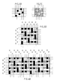
- FIG. 3D A possible binding cartridge for the tissue 10 'according to FIG. 3A is shown in FIG. 3D.
- the threads 12, 13 of the upper fabric 17 are denoted by “O” and the threads 12 ′′, 13 ′′ of its lower fabric 18 by “U”.
- This binding cartridge is composed of the Atlas binding cartridges 1/4 and 4/1 shown in FIGS. 3B and 3C, FIG. 3B showing that of the upper fabric 17. If a twill weave is provided, the weave of the upper fabric 17 or lower fabric 18 according to FIG. 1D or inversely to it can be provided.
- binding cartridges 1/4 or 4/1 bindings of other numerical ratios can be provided which fit the type of binding in question, as in the case of the Atlas binding 1/6, 1/7, 1/8, ...
- An often useful weave derivative can be, for example, a fake satin weave, which has an even-numbered weave repeat, for example 6, or other suitable weave derivatives can also be used of preferably atlas or twill weaves.
- Binding repeat is the sum of the two numbers of the binding in question.
- a 1/4 binding therefore has a binding repeat 5.
- the possibility of also being able to provide binding derivatives, in particular derivatives of the two basic bindings Atlas and twill, is explained using the example of a twill weave, which in some cases can be expediently provided. With her, each warp thread alternately bridges a weft thread, then two weft threads, then another weft thread, etc. Such a twill weave derivation is therefore a mixed weave 1/4 and 2/4. As a result, the ridges on the front of the fabric, which run obliquely to the warp and weft direction, become clearer, which is appropriate if the reflection effect caused by this should be desired for some reason.
- FIG. 4A shows a partial section through an uncoated double fabric 10 'with filler threads 20 forming a projection wall 10.
- This double fabric 10' consists of an upper fabric 17 made of light threads 12, 13, of which the light threads 12 dominating here on the front 11 of this Float tissue, whereas the light threads 13, which are perpendicular to the threads 12, float less or preferably not at all on this front side 11.
- the lower fabric 18 either consists entirely of dark threads 12 ′′, 13 ′′, or only one of its two thread systems consists of dark threads, preferably the thread system 12 ′′ which is floating on the underside of the fabric.
- the dark threads can Weft threads and / or warp threads are part of the lower fabric 18.
- filling threads 20 are arranged in one of the two main directions of the fabric 10 ', which thus form a layer of filling threads 20 or a single filling thread system.
- these filler threads 20 are only inserted between the upper fabric 17 and the lower fabric 18 and thus do not bind themselves and are also not bound by threads of the upper fabric or of the lower fabric, but only by the threads that pass between the adjacent filler threads and serve as binding threads 12 '', which bind the lower fabric 18 to the upper fabric 17, so that they cannot slip disruptively.
- FIG. 4B A possible weave cartridge of a fabric 10 ', a partial section of which is shown in FIG. 4A, is shown in FIG. 4B.
- This binding cartridge is derived from the binding cartridge according to FIG. 3D by inserting the filler threads 20, which are indicated here with "F".
- the filling threads 20 can preferably be light threads and preferably also be thicker and / or stiffer than the threads of the upper fabric 17 and the lower fabric 18, in order to thereby stiffen the fabric, whereby the risk of wave formation or wrinkling is particularly well countered even in difficult cases can.
- the type of weave of such fabrics 10 ' can also be provided in such a way that the bright threads 12 of the thread system in question floating on the front 11 of the fabric 10' or a partial number of these threads, for example each second or third of these threads are tied to the lower fabric 18 (one speaks here in technical terms of "tying"), as shown in FIG. 5A using an example.
- the threads 12 ′′ are then laid in such a way that they do not bind the upper fabric 17.
- Other modifications of the fabric 10 'according to FIGS. 3A and 4A are also possible.
- FIG. 5B shows a plan view of a section of the projection surface 11 of a fabric 10 'according to FIG. 5A, an satin weave 1/4 being assumed and all the threads 12, 13 of the visible upper fabric 17 being light threads, for example white or silver threads.
- 6A shows a partial section through an uncoated triple fabric 10 'consisting of an upper fabric 17, an intermediate fabric 23 and a lower fabric 18, forming a projection wall 10.
- all threads 12 ′′ and 13 ′′ of the thread systems 24 and 25 of its lower fabric 18 or only the threads of the thread system 25 of its lower fabric 18 can consist of dark threads 12 ′′, 13 ′′ and all other threads, in particular the threads Threads 12, 13 of its upper fabric 17 and the threads 26, 26 'of its intermediate fabric 23 suitably consist of light threads.
- the upper fabric 17 has the uppermost warp thread system
- the intermediate fabric 23 has the middle warp thread system
- the lower fabric 18 has the lowest warp thread system.
- the light threads 12 floating and dominating on the front side 11 of this fabric 10 ′ which has or forms the projection surface 11 are weft threads of the upper fabric 17.
- the intermediate fabric 23 can be woven in the same weave as the upper fabric 17, that is, in A 1/4, but its threads 26 also serve to bind threads 13 of the upper fabric 17.
- the lower fabric 18 can also have an atlas weave, here the weave A 4/1, and is connected to the intermediate fabric 23 by means of all or part of its threads 12 ′′, as shown, so that all the partial fabrics 17, 18, 23 are connected to one another.
- An advantageous possible binding cartridge of the fabric 10 'according to FIG. 6A is shown in FIG. 6B.
- the threads of the upper fabric 17 are here denoted by "O"
- the threads of the intermediate fabric 23 by "Z”
- the threads of the lower fabric 18 by "U”.
- the threads of the one thread system of such a partial fabric which are used for tying or tying up another or several other partial fabrics, can be all threads of this thread system in question or, what is generally more advantageous, only a partial number of these threads, preferably every nth thread of the thread system in question, where n is a whole Number 2, 3, 4, ... is. This generally applies to all possible tissues in which two or more partial tissues are connected to one another to form an overall tissue.
- the weaves of the upper fabric 17, intermediate fabric 23 and lower fabric 18 of a triple fabric 10 ' can be the same or different. At least the upper fabric 17 can preferably be provided in an atlas weave. The intermediate fabric 23 and the lower fabric 18 can then be provided, for example, in twill weave or also in satin weave or only the intermediate fabric or the lower fabric in twill weave, etc. Other weave combinations are also possible. E.g. In some cases the upper fabric and / or the intermediate fabric and / or the lower fabric could also be provided in plain weave or from a weave derived from it, for example in a grosgrain weave shown in FIG. 6C.
- the thread density of its thread system forming the dominant light threads can be provided with a much higher thread density than that of its other thread system, see also the following embodiment according to FIGS. 7A and 7B, whose fabric 10 ', for example, also as the upper fabric 17 a multiple fabric can be provided, which upper fabric can preferably consist entirely of light threads.
- FIG. 7A shows a partial section through a projection wall 10, which consists of a fabric 10 ′ formed here as a single fabric and a coating 30 on the back thereof.
- the back coating 30 is formed by a film 30 glued or welded to the fabric 10 '.
- the uncoated front side 11 of the fabric 10 'consisting of warp threads and weft threads forms the projection surface 11 of this projection wall 10 in whole or essentially.
- This projection screen 10 can also be wound up, that is to say flexibly.
- the film 30 is dark, preferably black, so that this projection screen is completely or largely opaque.
- the threads 12 are the dominant light threads of the projection surface 11 and form a thread system 17.
- the threads 13 woven with them and running transversely to them can also be light threads, if desired also dark threads, and form the second thread system 18 of the fabric 10 '.
- this fabric 10 ' has a plain weave, as the top view in FIG. 7B shows, but the fabric can also have any other suitable design.
- the front side serving as the projection surface 11 of this fabric 10 has the desired anisotropic properties, which are largely or essentially determined by the dominant bright threads 12 of the thread system 17 which run vertically when the projection wall 10 is vertical, here the threads 12 of the thread system 17 are in high, preferably as high as possible thread density laid so that they rest against each other, preferably are pressed against each other and leave no gaps between them.
- the in the projection position i.e. in the vertical, flat position of this projection wall 10 horizontally running threads (transverse threads) 13 of the thread system 18, on the other hand, are laid with a very low thread density by having large gaps between them, preferably spaces that are several times or many times larger than the diameter of these threads 13, such as 7A and 7B show an example.
- These "transverse threads" 13 can, however, preferably be thicker than the threads 12, in order to give this fabric good mechanical stability despite the low thread density of the transverse threads 13.
- This stability can be increased by the film 30.
- This film 30 is preferably thin to very thin so that the weight per unit area of this projection wall 10 is still relatively low despite this coating and this projection wall can also be easily wound up.
- the fabric 10 'provided on the back with a coating 30 can also have other constructions, for example fabric structures according to FIGS Embodiments according to FIGS. 1A, 2A, 3A, 4A, 5 and 6A. If this fabric has dark threads that already provide sufficient opacity of the projection screen, then the coating 30 cannot be dark and then only serves to increase the mechanical strength of the projection screen. If this is not necessary, the coating can be omitted and the fabric alone can form the projection screen.
- a projection wall device 40 is shown in a diagrammatic view in FIG. 8. It has a projection wall 10, which is normally located within a box 42, in which it is wound and held on a winding shaft, not shown.
- This box 42 can, for example, be fastened to a wall or ceiling of a room or be held on a frame (not shown) or have another arrangement.
- the projection wall 10, consisting of an uncoated fabric 10 'or a back-coated fabric 10', is rectangular or square and carries a weighting rod 43 on its lower edge.
- This projection wall 10 can be pulled out of the box 42, as shown, in such a way that it extends is substantially or entirely outside the box 42 vertically and in a flat shape, that is in the projection position of its projection surface and it can then serve for the reproduction of individual images or films which project images onto the projection surface formed entirely or partially by its vertical flat front side 11 will.
- This Fabric 10 ' is designed in accordance with the invention in such a way that it has the described anisotropic reflection properties, for example reflection properties similar to or equal to the luminance curves shown in the diagram in FIG. 9, depending on the horizontal and vertical radiation angles a, -a, b, -b.
- This white light striking the projection surface 11 is largely reflected.
- light rays emanating from a small surface area of the projection wall 10 are drawn in, namely two light rays RH1 and RH2 in the geometric plane E1 and two light rays RV1 and RV2 in the vertical geometric plane E2, the intersection of these two planes being shown the light beam S and the surface normal N fall, to which the horizontal beam angles a, -a and vertical beam angles b, -b are related.
- the fabric of the projection screen 10 shown in FIG. 8 can consist of a single fabric web, but possibly also be composed of a plurality of fabric webs that are sewn, glued or otherwise connected, for example, preferably parallel to one another with or without overlap and / or are arranged one above the other.
Landscapes
- Physics & Mathematics (AREA)
- General Physics & Mathematics (AREA)
- Woven Fabrics (AREA)
- Overhead Projectors And Projection Screens (AREA)
Applications Claiming Priority (2)
| Application Number | Priority Date | Filing Date | Title |
|---|---|---|---|
| DE19904001458 DE4001458C2 (de) | 1990-01-19 | 1990-01-19 | Projektionswand |
| DE4001458 | 1990-01-19 |
Publications (2)
| Publication Number | Publication Date |
|---|---|
| EP0438161A2 true EP0438161A2 (fr) | 1991-07-24 |
| EP0438161A3 EP0438161A3 (en) | 1992-06-10 |
Family
ID=6398373
Family Applications (1)
| Application Number | Title | Priority Date | Filing Date |
|---|---|---|---|
| EP19910100556 Withdrawn EP0438161A3 (en) | 1990-01-19 | 1991-01-18 | Projection screen |
Country Status (2)
| Country | Link |
|---|---|
| EP (1) | EP0438161A3 (fr) |
| DE (1) | DE4001458C2 (fr) |
Cited By (4)
| Publication number | Priority date | Publication date | Assignee | Title |
|---|---|---|---|---|
| FR2798678A1 (fr) * | 1999-09-21 | 2001-03-23 | Gerard Debard | Tissus pour l'audio et la lumiere |
| WO2005024506A3 (fr) * | 2003-09-02 | 2005-05-12 | Screen Res | Ecran de projection, notamment pour la videoprojection reduisant l’effet moire |
| US20230166175A1 (en) * | 2020-05-08 | 2023-06-01 | Golfzon Co., Ltd. | Screen for screen golf and manufacturing method of the same |
| CN117702341A (zh) * | 2023-10-31 | 2024-03-15 | 魏桥纺织股份有限公司 | 一种改善彩色像景画面精细度的织物组织设计方法 |
Families Citing this family (1)
| Publication number | Priority date | Publication date | Assignee | Title |
|---|---|---|---|---|
| DE102005057331A1 (de) * | 2005-11-28 | 2007-05-31 | Faurecia Innenraum Systeme Gmbh | Verkleidungsteil mit reflektierender Oberfläche |
Family Cites Families (3)
| Publication number | Priority date | Publication date | Assignee | Title |
|---|---|---|---|---|
| JPS52130325A (en) * | 1976-04-23 | 1977-11-01 | Schudel Conrad | Movie screen |
| US4132462A (en) * | 1977-09-12 | 1979-01-02 | Acushnet Company | Filamentary projection system |
| US4281688A (en) * | 1979-05-01 | 1981-08-04 | Scapa Dryers (Canada) Ltd. | Reversible forming fabric having dominating floats on each face |
-
1990
- 1990-01-19 DE DE19904001458 patent/DE4001458C2/de not_active Expired - Fee Related
-
1991
- 1991-01-18 EP EP19910100556 patent/EP0438161A3/de not_active Withdrawn
Cited By (8)
| Publication number | Priority date | Publication date | Assignee | Title |
|---|---|---|---|---|
| FR2798678A1 (fr) * | 1999-09-21 | 2001-03-23 | Gerard Debard | Tissus pour l'audio et la lumiere |
| WO2001021872A1 (fr) * | 1999-09-21 | 2001-03-29 | Giry Francois | Tissus pour l'audio et la lumiere |
| WO2005024506A3 (fr) * | 2003-09-02 | 2005-05-12 | Screen Res | Ecran de projection, notamment pour la videoprojection reduisant l’effet moire |
| CN1846168B (zh) * | 2003-09-02 | 2010-04-28 | 屏幕研究公司 | 尤其用于降低莫尔条纹效应的视频的投影屏幕 |
| US7777947B2 (en) | 2003-09-02 | 2010-08-17 | Screen Research | Projection screen, in particular for video projection reducing the Moiré effect |
| US20230166175A1 (en) * | 2020-05-08 | 2023-06-01 | Golfzon Co., Ltd. | Screen for screen golf and manufacturing method of the same |
| US12053686B2 (en) * | 2020-05-08 | 2024-08-06 | Golfzon Co., Ltd. | Screen for screen golf and manufacturing method of the same |
| CN117702341A (zh) * | 2023-10-31 | 2024-03-15 | 魏桥纺织股份有限公司 | 一种改善彩色像景画面精细度的织物组织设计方法 |
Also Published As
| Publication number | Publication date |
|---|---|
| DE4001458C2 (de) | 1994-06-01 |
| DE4001458A1 (de) | 1991-07-25 |
| EP0438161A3 (en) | 1992-06-10 |
Similar Documents
| Publication | Publication Date | Title |
|---|---|---|
| AT398091B (de) | Doppelgewebe für eine papiermaschine | |
| DE69528113T2 (de) | Eine Kleinstruktur für Farbdarstellung durch Reflexion und Interferenz von natürlichem Licht | |
| DE69832565T2 (de) | Durchlicht-Projektionsschirm | |
| EP2080062A2 (fr) | Tissu de rétroprojection, écran de rétroprojection et système de rétroprojection | |
| DE69632589T2 (de) | Jalousielamelle aus stoff | |
| DE69217139T2 (de) | Polarisierender Projektionsschirm und Projektor dazu | |
| DE69432648T2 (de) | Polarisierender Projektionsschirm | |
| DE69427250T2 (de) | Projektionsschirm | |
| DE3785262T2 (de) | Durchscheinender Projektionsschirm. | |
| EP0325167A1 (fr) | Toile à deux couches pour la section de formation d'une machine à papier | |
| DE2342651C2 (de) | Kathodenstrahlröhre und Verfahren zu ihrer Herstellung | |
| DE2901580A1 (de) | Elektrooptische anzeige mit reflektor | |
| DD291691A5 (de) | Schatten- und isolierschirm aus wasseraufsaugendem textilgewebe und verfahren zu herstellung | |
| DE60119340T2 (de) | Trockensieb | |
| DE69707375T2 (de) | Durchlicht-Projektionsschirm | |
| EP3058123B1 (fr) | Système pour guider de la lumière | |
| DE102017129450B4 (de) | Hautmaterial für Fahrzeuginnenräume | |
| DE69320177T2 (de) | Vorhang | |
| DE4001458C2 (de) | Projektionswand | |
| DE1535442A1 (de) | Dreiachsiges Gewebe | |
| DE10007375A1 (de) | Felgenschlauch aus textilem Fadenmaterial zur Befestigung mindestens eines schallschluckenden Körpers | |
| DE3545174C1 (de) | Mitlaeufergewebe | |
| DE102009056820B4 (de) | Rollostoffbahn | |
| DE4039958C2 (de) | Aufwickelbare Lichtbildwand | |
| DE3202030C2 (fr) |
Legal Events
| Date | Code | Title | Description |
|---|---|---|---|
| PUAI | Public reference made under article 153(3) epc to a published international application that has entered the european phase |
Free format text: ORIGINAL CODE: 0009012 |
|
| AK | Designated contracting states |
Kind code of ref document: A2 Designated state(s): AT BE CH DE DK ES FR GB GR IT LI LU NL SE |
|
| PUAL | Search report despatched |
Free format text: ORIGINAL CODE: 0009013 |
|
| AK | Designated contracting states |
Kind code of ref document: A3 Designated state(s): AT BE CH DE DK ES FR GB GR IT LI LU NL SE |
|
| 17P | Request for examination filed |
Effective date: 19921121 |
|
| 17Q | First examination report despatched |
Effective date: 19940810 |
|
| STAA | Information on the status of an ep patent application or granted ep patent |
Free format text: STATUS: THE APPLICATION IS DEEMED TO BE WITHDRAWN |
|
| 18D | Application deemed to be withdrawn |
Effective date: 19950110 |